• Photonics Research
  • Vol. 11, Issue 4, 504 (2023)
Lang Li1、2、†, Tao Wang1、2、5、†,*, Xinhang Li3、†, Peng Huang1、2, Yuyao Guo3, Liangjun Lu3、4、6、*, Linjie Zhou3、4, and Guihua Zeng1、2、7、*
Author Affiliations
  • 1State Key Laboratory of Advanced Optical Communication Systems and Networks, Center for Quantum Sensing and Information Processing, Department of Electronic Engineering, Shanghai Jiao Tong University, Shanghai 200240, China
  • 2Shanghai Research Center for Quantum Sciences, Shanghai 201315, China
  • 3State Key Laboratory of Advanced Optical Communication Systems and Networks, Shanghai Key Laboratory of Navigation and Location Services, Department of Electronic Engineering, Shanghai Jiao Tong University, Shanghai 200240, China
  • 4SJTU-Pinghu Institute of Intelligent Optoelectronics, Pinghu 314200, China
  • 5e-mail: tonystar@sjtu.edu.cn
  • 6e-mail: luliangjun@sjtu.edu.cn
  • 7e-mail: ghzeng@sjtu.edu.cn
  • show less
    DOI: 10.1364/PRJ.473328 Cite this Article Set citation alerts
    Lang Li, Tao Wang, Xinhang Li, Peng Huang, Yuyao Guo, Liangjun Lu, Linjie Zhou, Guihua Zeng. Continuous-variable quantum key distribution with on-chip light sources[J]. Photonics Research, 2023, 11(4): 504 Copy Citation Text show less

    Abstract

    Integrated quantum key distribution (QKD) systems based on photonic chips have high scalability and stability, and are promising for further construction of global quantum communications networks. On-chip quantum light sources are a critical component of a fully integrated QKD system; especially a continuous-variable QKD (CV-QKD) system based on coherent detection, which has extremely high requirements for the light sources. Here, for what we believe is the first time, we designed and fabricated two on-chip tunable lasers for CV-QKD, and demonstrated a high-performance system based on these sources. Because of the high output power, fine tunability, and narrow linewidth, the involved on-chip lasers guarantee the accurate shot-noise-limited detection of quantum signals, center wavelength alignment of nonhomologous lasers, and suppression of untrusted excess noise. The system’s secret key rate can reach 0.75 Mb/s at a 50 km fiber distance, and the secure transmission distance can exceed 100 km. Our results mark a breakthrough toward building a fully integrated CV-QKD, and pave the way for a reliable and efficient terrestrial quantum-secure metropolitan area network.

    1. INTRODUCTION

    Quantum key distribution (QKD), a kind of quantum cryptography technology, has been theoretically proven to be able to provide unconditional secure communications. In the past several decades, QKD has been studied and can be deployed in real-world fiber networks [13]. Integrated and miniaturized QKD systems provide a constructive solution to realize highly stable, low-cost, portable, compact, and robust global ultralarge-scale quantum communications networks [48]. The key to the integrated QKD is the integration of a light source, a linear element, and a detector. The integration of quantum photonic components has already been reported [914], and a QKD system integration has been initially demonstrated, which means there is movement toward a fully integrated QKD system [15].

    Generally, there are two categories of QKD schemes: discrete-variable QKD (DV-QKD) and continuous-variable QKD (CV-QKD). The integration of DV-QKD has made significant progress, and integrated DV-QKD systems are mainly divided into two categories. The first category includes those with integrated light sources, such as an indium phosphide (InP) transmitter chip including an on-chip DBR laser [coherence time>1.5  ns, side-mode suppression ratio (SMSR)>50  dB, operating wavelength of 1550 nm with 10  nm tuning range] and a silicon nitride receiver chip, which achieves 568 kb/s secure key rate for an emulated 20 km fiber link [9]. Measurement device independent (MDI)-QKD has been demonstrated between two independent InP transmitters with on-chip lasers (linewidth of 30 pm, SMSR of 50 dB, and a tuning capability of 10 nm in the C-band), which achieves 12 kb/s over a 25 km emulated fiber link and 1 kb/s over a 100 km emulated fiber link [11]. Very recently, a fully integrated QKD system has been proposed with a phase-seeded QKD transmitter including two on-chip diode lasers (coherence time 100  ns, linewidth <4.5  MHz). This QKD system can achieve 248 kb/s over a secure transmission distance up to 50 km on standard fibers [16,17]. We can clearly see that the maximum transmission distance of all the integrated (fully and partially integrated) DV-QKD systems with on-chip lasers is currently no more than 50 km. In the second type, only the passive device is integrated without the on-chip light source. A silicon photonic polarization encoder with an off-chip laser is demonstrated, which achieves 157 kb/s in an intercity metropolitan test on a 43 km fiber (with a 16.4 dB loss) [10]. A silicon chip-based polarization-encoded MDI-QKD system with two transmitter chips based on off-chip lasers achieves a finite-key secret rate of 31 b/s over 36 dB channel loss and 497 b/s over 140 km commercial fiber spools [12]. A high-speed QKD transmitter based on silicon photonic integrated circuits and an off-chip laser is demonstrated with 329 kb/s over a 20 km fiber link [13]. A silicon polarization-encoded QKD transmitter with an off-chip laser is presented, which was used in a proof-of-concept demonstration of the BB84 QKD protocol with 0.95 kb/s over a 5 km long fiber link [14]. For CV-QKD, an integrated CV-QKD system with an off-chip light source, has been verified in principle recently under laboratory conditions [8]. This work demonstrates the feasibility of a CV-QKD on an integrated chip platform.

    A light source generating designated quantum states is the critical component for an integrated QKD system. Although integrated light sources have been demonstrated in DV-QKD systems [9,11], they have not been studied in CV-QKD systems since the proposal of the GG02 protocol [18,19], especially with a local local oscillator (LLO) scheme. The current integrated CV-QKD is based on the transmitted local oscillator (TLO) scheme, which can guarantee the consistency of the LO wavefront and signal to achieve stable homodyne detection [8]. However, the crosstalk from the LO limits the development of long-distance transmission and causes potential practical security problems. Fortunately, a CV-QKD system based on the LLO scheme has been proposed, which can ensure that the quantum detection reaches the shot-noise limit under long-distance transmission conditions, and significantly eliminates the signal’s crosstalk by a more robust LO [20,21]. Meanwhile, since the LO is generated locally at the receiver, potential security loopholes are eliminated from the source. Therefore, a CV-QKD system based on an LLO scheme provides an up-and-coming solution for integrated CV-QKD systems.

    However, an integrated LLO CV-QKD system has extremely high requirements for light sources. Most QKD realization requires only one laser source, but an LLO scheme requires two. The three main requirements for on-chip lasers are: (1) an accurate wavelength tunability to meet the alignment of the center wavelengths of two lasers; (2) a sufficient optical output power to ensure shot-noise-limited detection; and (3) a narrow linewidth and low noise to guarantee low untrusted excess noise and secure key generation. Therefore, it is still challenging to have two on-chip light sources with narrow linewidths, low noise, fine tunability, and simultaneously sufficient power, which is crucial for high-performance LLO CV-QKD realization.

    In this paper, we implemented a compact, high-performance III-V/Si3N4 external cavity laser (ECL) that features high output, narrow linewidth, broad wavelength tunability, and high SMSR. A complete LLO CV-QKD system with a secure transmission distance exceeding 100 km is realized. This work has taken a crucial step to solve the bottleneck of the integrated on-chip laser source in high-performance integrated QKD systems, especially the integrated LLO CV-QKD systems in the past two decades since the proposal of the GG02 protocol [18,19]. We perform almost perfect correction and compensation for the frequency offset and phase drift, and finally achieve the secure key of 0.75 Mb/s under 50 km. This integrated CV-QKD system based on the LLO scheme solves both the upper limit of long-distance transmission and the practical security issues. Meanwhile, we have overcome the problems of high-performance on-chip laser integration commonly faced by an integrated QKD system. We extend the applicability of the IIIV/Si3N4 ECL to CV-QKD and the potential to other quantum information applications. This system perfectly complements previous work on CV-QKD systems on a chip, paving the way for the full integration of metro CV-QKD networks.

    2. ON-CHIP QUANTUM LIGHT SOURCE

    In terms of low excess system noise, minor frequency offset between a signal and an LO, shot-noise-limited detection, and accurate detection requirements of a high-performance fully integrated LLO CV-QKD system, the on-chip quantum light source should simultaneously meet four important conditions: narrow linewidth, high tunability, sufficient output optical power, and high frequency stability. Therefore, we created a design to solve the quantum light source integration problem in a fully integrated CV-QKD system for high performance. The inset of Fig. 1(a) illustrates the full schematic structure of the two ECLs used in the system. The laser consists of an InP reflective semiconductor optical amplifier (RSOA) chip butt-coupled with a low-loss silicon nitride cavity extension chip. The rear side of the RSOA is coated with a high-reflection (HR) film to serve as the back mirror of the ECL. The waveguide is slanted by 8° at the front side and coated with an anti-reflection (AR) film to reduce the interface reflection. The coupling loss between the RSOA and external cavity is about 2.5 dB.

    (a) Schematic of the optical layer of the LLO-CV-QKD system with an on-chip III-V/Si3N4 external cavity laser. The integrated system contains two parties, Alice and Bob, as, respectively, the transmitter and receiver. Alice’s side consists of an isolator (Iso), two attenuators (ATTs), an amplitude modulator (AM), a beam splitter (BS), an IQ-modulator (IQ MOD), and a DC supply. Bob’s side has two polarization controllers (PCs) and an integrated coherent receiver (ICR). The photon detectors (PDs) are used for optical power monitoring. The inset shows the schematic structure of the external cavity lasers (ECLs). (b) Photograph of the packaged ECLs. The RSOA is butt-coupled to an extension chip. The laser is supplied with electric current via wires. The on-chip light is measured and used in the QKD system using an optical fiber. (c) Microscope photo of the ECL. The footprint of the external chip is 2.4 mm×1.27 mm.

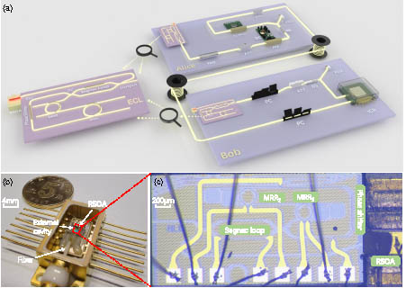
    Figure 1.(a) Schematic of the optical layer of the LLO-CV-QKD system with an on-chip III-V/Si3N4 external cavity laser. The integrated system contains two parties, Alice and Bob, as, respectively, the transmitter and receiver. Alice’s side consists of an isolator (Iso), two attenuators (ATTs), an amplitude modulator (AM), a beam splitter (BS), an IQ-modulator (IQ MOD), and a DC supply. Bob’s side has two polarization controllers (PCs) and an integrated coherent receiver (ICR). The photon detectors (PDs) are used for optical power monitoring. The inset shows the schematic structure of the external cavity lasers (ECLs). (b) Photograph of the packaged ECLs. The RSOA is butt-coupled to an extension chip. The laser is supplied with electric current via wires. The on-chip light is measured and used in the QKD system using an optical fiber. (c) Microscope photo of the ECL. The footprint of the external chip is 2.4mm×1.27mm.

    To meet the low excess noise requirements, the on-chip laser should have a narrow linewidth (low frequency noise). Traditional monolithic III-V lasers such as DFB lasers, sampled-grating DBR (SG-DBR) lasers, and vertical cavity surface-emitting lasers (VCSELs), have a relatively large linewidth due to the short cavity and large internal loss [22]. Compared to these lasers, ECLs composed of III-V gain and passive circuits are a solution to narrow the linewidth. To reduce the intrinsic linewidth to a kHz-level (coherence time of 0.1–1 ms), we use the low loss Si3N4 waveguide (0.3 dB/cm) to implement the external cavity with an effective length of about 26.8 mm. The low-loss long laser cavity extends the photon lifetime. Moreover, a well-known negative feedback loop (detuned loading effect) stabilizes the laser [23]. Both contribute to a narrower linewidth, resulting in a significant reduction in the excess noise in the CV-QKD system (see Appendix A).

    The minor frequency offset between the signal and the LO demanded in the system means that the on-chip laser should provide high tunability. We designed a high-performance mode selection filter in the passive cavity composed of a Vernier filter based on two microrings (MRRs) to provide high SMSR and a wide wavelength tuning range. The circumferences of the two MRRs are 583 μm and 565 μm, corresponding to free spectral ranges (FSRs) of 1.93 nm and 1.99 nm, respectively. The extended FSR can exceed 60 nm. A phase shifter is also integrated in the cavity to align the wavelength with the passband center of the filter. The Vernier filter ensures high-performance, single-mode lasing and attenuates the side modes and amplified spontaneous emission noise (ASE) prior to the lasing output. The single lasing mode is controlled by aligning the resonances of two MRRs by tuning one MRR. The coarse tuning range measured by an optical spectrum analyzer (AQ6370D-12, 0.02 nm wavelength resolution; Yokogawa Electric) is more than 70 nm, as shown in Fig. 2(d). The wide wavelength tuning range is suitable for high-capacity quantum communications, wavelength division multiplexing systems, and more potential quantum information applications [24,25]. The lasing frequency can be continuously tuned over a long range by synchronously driving the MRRs and the phase shifter. The resulting fine-tuning range is about 30 GHz (limited by the maximum allowed heating power of the phase shifter) depicted in Fig. 2(b), which ensures the minor frequency offset between nonhomologous lasers. Additionally, Fig. 2(c) shows that the maximum SMSR of this ECL is up to 75 dB.

    (a) L-I curve at the wavelength of 1545 nm. The lasing threshold is 38.9 mA, and the slope efficiency is about 238 mW/A. The maximum on-chip output of 47.3 mW is obtained at a 236 mA injection current. The fiber-to-chip coupling loss is measured to be about 3 dB. (b) Superimposed output spectra of continuous frequency tuning by synchronously driving two Vernier MRRs and a phase shifter. The continuous frequency tuning range is 30 GHz. (c) Output spectrum showing the single-mode lasing with an SMSR above 75 dB. (d) Measured superimposed lasing spectra of the ECL during coarse wavelength tuning. When it turns on the RSOA, the initial center wavelength is around 1498 nm. By tuning one of the MRRs, the lasing wavelength shifts from 1498 to 1531 nm with a step equalling the FSR of the MRR. When tuning the other MRR, the lasing wavelength first shifts to 1491 nm step by step, then jumps to 1564 nm, corresponding to the tuning range of the laser, and finally shifts to 1532 nm. The current of the RSOA is adjusted to make the output power close to the same level over the whole range. The wavelength tuning range is around 73 nm from 1491 to 1564 nm with an SMSR more than 65 dB.

    Figure 2.(a) L-I curve at the wavelength of 1545 nm. The lasing threshold is 38.9 mA, and the slope efficiency is about 238 mW/A. The maximum on-chip output of 47.3 mW is obtained at a 236 mA injection current. The fiber-to-chip coupling loss is measured to be about 3 dB. (b) Superimposed output spectra of continuous frequency tuning by synchronously driving two Vernier MRRs and a phase shifter. The continuous frequency tuning range is 30 GHz. (c) Output spectrum showing the single-mode lasing with an SMSR above 75 dB. (d) Measured superimposed lasing spectra of the ECL during coarse wavelength tuning. When it turns on the RSOA, the initial center wavelength is around 1498 nm. By tuning one of the MRRs, the lasing wavelength shifts from 1498 to 1531 nm with a step equalling the FSR of the MRR. When tuning the other MRR, the lasing wavelength first shifts to 1491 nm step by step, then jumps to 1564 nm, corresponding to the tuning range of the laser, and finally shifts to 1532 nm. The current of the RSOA is adjusted to make the output power close to the same level over the whole range. The wavelength tuning range is around 73 nm from 1491 to 1564 nm with an SMSR more than 65 dB.

    The shot-noise-limited detection requirements in a high-performance integrated CV-QKD system require the on-chip lasers to provide sufficient optical power. The output power of the ECL partially depends on the loss of the external cavity. Si3N4 has proven to have a lower linear and nonlinear transmission loss compared to silicon waveguides, and thus can achieve a higher optical power and a narrower linewidth [2628]. The relatively large index contrast of Si3N4 waveguides also ensures the small bending radius of Vernier MRRs in the design. LiNbO3-on-insulator (LNOI) is a rising platform for high-performance, low-loss optical devices [29,30]. However, the photorefractive effect in LNOI potentially degrades the output power stability of LNOI-based ECLs. Therefore, we chose to implement Si3N4 waveguides as passive extension chips to provide sufficient optical power. We also designed a tunable Sagnac loop (TSL) with tunable reflectivity as another ECL mirror. The reflectivity can be tuned from 0 to 1 in the 70 nm wavelength range by controlling the phase difference of the Mach–Zehnder interferometer (MZI) arms (see Appendix A). Both the low loss and tunable reflectivity contribute to a maximum on-chip output of 47.3 mW, as shown in Fig. 2(a), which meets the requirements of shot-noise-limited detection under long distance and fully guarantees the practical security of CV-QKD in an implementation.

    Accurate detection requires the ECL to have a high frequency stability. Because thermal management of side-placed chips is easier than 3D integration [31,32], a high frequency stability is expected. In our experiment, a thermoelectric cooler (TEC) is placed under the chips to dissipate the heat produced by the laser. During the operation, the TEC temperature was fixed at 20°C.

    Figure 1(b) shows the ECL packaged in butterfly shells. Figure 1(c) is a microscope photo of the integrated laser. With the high-performance on-chip ECL suitable for the CV-QKD system, we will demonstrate its superior performance in the LLO CV-QKD system for practical long-distance fiber transmission.

    3. EXPERIMENT FOR CV-QKD

    We experimentally demonstrate a pilot-assisted LLO CV-QKD in a 50–100 km long fiber link with well-designed chip sources. Figure 1 shows the experimental setup. At the transmitter, Alice first uses one isolator and one attenuator (ATT) to control the optical power from the CW on-chip laser, and then employs a high performance LiNbO3 amplitude modulator (AM) to produce a series of coherent state pulses. The AM’s bias voltage is controlled by a high-precision DC power supply. Then a beam splitter (BS) is used to split this state into two portions with an intensity ratio of 99:1. The small part is used for optical monitoring, while the large part generates the quantum signal and the pilot signal. Subsequently, an IQ modulator (IQ MOD) modulates the signal, and two electronic signals carrying Gaussian-distributed random numbers are generated by an arbitrary waveform generator (AWG) and amplified by a microwave amplifier. The coherent states are modulated to |xA+ipA, where xA and pA follow a centered Gaussian distribution and then are adjusted to a suitable variance of VA by tuning another ATT. The pilot-data channel pair is transmitted through the fiber link on one polarization. At the receiver, with the help of a manual polarization controller (PC), the time-multiplexing pilot-data pulses are injected into an integrated coherent receiver (ICR) for detection. In addition, an intense LO is generated by another on-chip laser, and its polarization is adjusted by another PC. A photon detector monitors the LO intensity, and finally, the LO is injected into the ICR and mixed with the signal. The phase information of the pilot is used to compensate for the raw data of the signal, from which the final key can be distilled.

    To keep the frequency offset minor between the signal light and LO light, we adjusted the two lasers simultaneously to make the spectral peaks distinguishable, as shown in Fig. 3(a). Then we connected these two lasers to the QKD system. We adjusted the phase shifter to reduce the beat frequency until it was below 20 MHz. The beat frequency drifts over time. Figure 3(b) shows the histogram of the measured beat frequency after a period of time. The change of the central wavelength of the laser leads to a drift of beat frequency, which may originate from two sources. The output of the voltage source gives ripple noise and, as the TEC is placed on the lower surface of the chip, the local temperature of the chip is affected by the surrounding environment and is different from TEC. The frequency instability may introduce a certain amount of excess noise in the preparation of quantum states, thereby degrading the system performance. Therefore, we adopted a frame-by-frame processing algorithm in post-processing, and the beat frequency in each frame remains almost unchanged, which greatly reduces the impact of this frequency instability. As depicted in Fig. 3(c), we measured the frequency noise spectrum of the operating laser using an optical noise analyzer (A0040A, SYCATUS). The intrinsic linewidths of the signal and LO are 1.6 kHz and 3.2 kHz, respectively, calculated by multiplying the white frequency noise level by π in the high-frequency range (see Appendix A).

    (a) Optical spectrum of two lasers before (blue) and after (orange) adjustment. (b) Histogram of the measured beat frequency. When measuring the change of the beat frequency, we use a data volume of 5 Mb per frame and a sampling frequency of 10 Gb/s to measure the frequency offset of the beat frequency. After analyzing 800 frames of data, we found that the beat frequency of more than 70% of the frames is below 40 MHz, which sufficiently satisfies the demand of the system. (c) Frequency noise spectrum of the signal and the LO laser.

    Figure 3.(a) Optical spectrum of two lasers before (blue) and after (orange) adjustment. (b) Histogram of the measured beat frequency. When measuring the change of the beat frequency, we use a data volume of 5 Mb per frame and a sampling frequency of 10 Gb/s to measure the frequency offset of the beat frequency. After analyzing 800 frames of data, we found that the beat frequency of more than 70% of the frames is below 40 MHz, which sufficiently satisfies the demand of the system. (c) Frequency noise spectrum of the signal and the LO laser.

    4. PERFORMANCE ANALYSIS

    The quantum efficiency and electronic noise of this QKD system were calibrated in advance. The quadrature selection is achieved by maximizing the cross-modulation peak-to-peak difference. Both the output signal and the input signal for x and p quadrature modulation are recorded, and the data are collected for 0.5 μs with a sampling frequency of 10 Gb/s. The output signal on Bob’s side is synchronized with Alice’s modulation signal by measuring their cross-correlation. Figure 4(a) shows the normalized cross-correlation measurement between the heterodyne detector output and the corresponding modulation signal, and the inset in Fig. 4(a) shows the raw secret key shared by Alice and Bob. All signals are synchronized based on the cross-correlation and pass through a digital lowpass filter. Next, the filtered signals are demodulated and downsampled to 0.5 Gb/s to generate a set of correlated Gaussian keys that are shown in Fig. 4(a) with Alice’s key as the x coordinate and Bob’s key as the y coordinate. These plots confirm that Bob’s key only correlates to one of Alice’s keys with the same measured quadrature. Information reconciliation is then applied to the correlated Gaussian key. Figure 4(b) shows the excess noise performance of the system.

    (a) Cross-correlation results of Bob’s measurement and Alice’s modulation on corresponding quadratures. Inset is the raw secret key shared by Alice and Bob. (b) Measured excess noise at 50 km. The error bars represent the measured excess noise at 50 km in the experiment, and the blue line represents the average excess noise of 60 frames of experimental data. (c) Secret key rate.

    Figure 4.(a) Cross-correlation results of Bob’s measurement and Alice’s modulation on corresponding quadratures. Inset is the raw secret key shared by Alice and Bob. (b) Measured excess noise at 50 km. The error bars represent the measured excess noise at 50 km in the experiment, and the blue line represents the average excess noise of 60 frames of experimental data. (c) Secret key rate.

    The secure key rate at a longer distance is calculated based on the assumption of a collective attack under the trusted device scenario, which means an eavesdropper cannot access the noise from Bob’s apparatus. Note that a coherent attack is an optimal attack, and it has proven to be equivalent to a collective attack under asymptotic conditions. The total losses consist of the losses on the transmission line and Bob’s equipment, while the losses on Alice’s side do not affect the final security key. Table 1 shows the main experimental parameters in the LLO-CV-QKD system with chip light sources under 50 and 100 km standard fiber links. These parameters can be achieved using the current post-processing scheme with the same SNR. The proportion of raw data used for the parameter estimation is 50%. Considering the unqualified excess noise (less than zero caused by statistical error or greater than the secret threshold), a part of the data is excluded through the post-selection. For a distance of 50 km, the qualified frame rate (QFR) is around 80%; for 100 km, around 10% of the frame can be used for subsequent data processing. With these remaining data, the secure key rate of the current CV-QKD system is estimated. Figure 4(c) shows the Shannon raw secret key rate. (From top to bottom, the solid black line represents the PLOB bound, the solid red line represents the expected LLO CV-QKD bound with a chip source, the orange pentagram represents experimental results of our LLO CV-QKD system with a chip source, the blue square represents the distance and secret key rate that have been achieved in the integrated TLO CV-QKD experiment [8], and the others represent related integrated DV-QKD works [9,10,13,14,17].)

    Summary of Experimental Parameters

    ParameterValue50 km/100 km
    Total excess noise ξ0.0579 SNUs50 km
    Channel transmittance T0.118650 km
    Qualified frame rate QFR80%50 km
    Total excess noise ξ0.0692 SNUs100 km
    Channel transmittance T0.0127100 km
    Qualified frame rate QFR10%100 km
    Modulation variance Vmod10 SNUs50 km/100 km
    Heterodyne detection efficiency ηhet42%50 km/100 km
    Detector electronic noise vel0.1850 km/100 km
    Symbol rate SR0.25 GBaud50 km/100 km
    Quantum efficiency ηquant97%50 km/100 km
    Frame error rate FER50%50 km/100 km

    To finally generate a secret key at such a lower SNR regime, multidimensional reconciliation and low-density parity check (LDPC) error correction codes are used to perform key extraction offline. The multidimensional reconciliation adopts the rotation algorithm to convert the Gaussian distributed data into binary distributed data [33]. The LDPC code adopts the rate-adaptive algorithm, the advantage of which is that the reconciliation efficiency can be maintained under a slight SNR fluctuation [34]. Through the parameter adjustment, we finally obtained the final secure key at 50 km and 100 km, respectively, and completed the whole process of key distribution. Such a result confirms the effectiveness of the integrated laser source in CV-QKD.

    5. CONCLUSION

    In conclusion, we have reported the use of on-chip III-V/Si3N4 external cavity lasers for a hundred-kilometer level, high-performance LLO CV-QKD. By giving the on-chip laser wavelength tunability, a narrow linewidth, and many other functional advantages, we creatively solved the challenge of integrating on-chip lasers that can truly support the long-distance practical metro optical fiber transmission networks of a CV-QKD system since the proposal of the GG02 protocol. Based on this on-chip quantum source, future demonstrations will focus on a fully integrated high-performance LLO-CV-QKD system that eliminates the security flaws in the physical mechanism of the previous integrated CV-QKD system based on the TLO. Moreover, it technically realizes the experimental verification in the actual optical fiber transmission environment of metropolitan application scenarios.

    APPENDIX A

    Laser Structure

    This hybrid integrated ECL consists of an InP reflective semiconductor optical amplifier (RSOA) butt-coupled with a Si3N4 external chip. As shown in Fig. 5, the Si3N4 waveguide has a thickness of 800 nm and a width of 1 μm. The thickness of the undercladding layer is 4 μm. An aluminum (Al) heater is placed above the waveguide, and the distance between the heater and the waveguide is 1.7 μm. The RSOA chip consists of five AlGaInAs quantum wells with a gain spectrum centered in the C-band. The rear side of the RSOA, acting as a mirror of the laser, has a high-reflection (HR) coating with a reflectivity of about 90%. The RSOA waveguide at the coupling facet is tilted at an angle of 8° to the normal and coated with an anti-reflection (AR) film. Two add–drop microrings (MRRs) with slightly different circumferences are integrated into the extended cavity. The free spectral range (FSR) of the two MRRs is given by [35] FSR1=λ02ngLMRR1,FSR2=λ02ngLMRR2,where ng is the MRR group index. The group index of the TE and TM modes is slightly different, but the RSOA mainly supports the TE mode; therefore, we only consider the TE mode. LMRR1 and LMRR2 are the circumferences of the two MRRs, which are equal to 583 μm and 565 μm, respectively. The FSRs of the two MRRs are calculated as 1.93 nm and 1.99 nm. Figure 6(a) shows the transmission spectrum of the two MRRs. The two sets of resonances are slightly mismatched; thus, the aligned resonance peaks are preserved while the misaligned ones are suppressed, resulting in an expansion of FSR, as shown in Fig. 6(b). The resulting FSR can be expressed as FSRfilter=FSR1·FSR2|FSR1FSR2|.The extended FSR is about 60 nm. The actual tuning range is larger than extended FSR. Both MRR process variations and the tunable reflectivity of the tunable Sagnac loop (TSL) contribute to the difference between the simulated extended FSR and the actual tuning range [36]. The two cascaded MRRs work as a Vernier filter to select a single longitudinal mode with the highest net gain. Applying a voltage onto the heater will change the waveguide temperature, which will lead to a phase shift of the light. A slight change in the laser cavity round-trip phase (including the RSOA, phase shifter, or MRRs) can result in a continuous shift of the lasing wavelength until it jumps to the adjacent longitudinal mode. The tunability ensures minor frequency offset between nonhomologous lasers. The Sagnac loop reflector forms the other mirror of the laser cavity. The power reflectivity of the conventional Sagnac loop (CSL) is written as RSL=4κDC2tDC2,where κDC and tDC are, respectively, the coupling and transmission coefficients of the coupler. κDC2 is defined as the power coupling coefficient (PCC). Different from CSL, we use the TSL in which a Mach–Zehnder interferometer (MZI) replaces the original DC. Therefore, the reflectivity can be tuned by controlling the phase difference of the MZI arms. We use the transfer matrix method (TMM) to derive the power reflectivity of the TSL based on the assumption that there is no loss in the photonics circuit. As shown in Fig. 7(d), the field transfer through TSL can be divided into seven stages: passing DC, MZI arms, DC, other devices, DC, MZI arms, and DC. S is the transfer function of the DC, and S is given by a matrix as S=(tDCjκDCjκDCtDC).The phase difference of θ occurs between two MZI arms when a voltage is applied on one arm. The transfer matrix Sarm of the MZI arms can be expressed as Sarm=(100ejθ).The phase change accumulated is φ when light passes the other devices. The transfer matrix Sfilter of other devices can be expressed as Sfilter=(0ejφejφ0).Then, the TSL transfer function is expressed as (E3E4)=SSarmSSfilterSSarmS(E1E2),where E1 and E2 are the input optical fields, and E3 and E4 are the output optical fields. The power reflectivity is derived by setting E1=0 and E2=1, so R=|E4|2=|2κDCtDCejφ[tDC2(ejθ+e2jθ)κDC2(ejθ+1)]|2.The reflectivity is mainly determined by the PCC and phase difference θ. The PCC of the DC varies with wavelength, as shown in Fig. 7(a). The PCC increases from 0.402 to 0.591 in the range of 1500–1600 nm. Figure 7(b) presents the relationship between the PCC and reflectivity based on different θ. When tuning the thermal phase shifter of one arm, the reflectivity of the different PCC (0.4–0.6 corresponds to 1500–1600 nm) will change. Figure 7(c) shows the function relation between the phase difference and reflectivity given the PCC. Note that when the PCC is in the range of 0.15–0.85, a full reflectivity tuning from 0 to 1 can be achieved by adjusting the phase shifter. The tunable reflectivity ensures the high output optical power that meets the requirements of shot-noise-limited detection.

    Cross section of the Si3N4 waveguide tuned by a metallic heater.

    Figure 5.Cross section of the Si3N4 waveguide tuned by a metallic heater.

    (a) Simulated add-drop transmission spectra of two MRRs. The FSR is, respectively, 1.93 nm and 1.99 nm for the two MRRs. The two sets of transmission spectra are aligned at 1.55 and 1.488 μm. (b) Simulated round-trip transmission spectrum of the external cavity. The extended FSR is more than 60 nm due to a slight difference in the circumference between the two MRRs.

    Figure 6.(a) Simulated add-drop transmission spectra of two MRRs. The FSR is, respectively, 1.93 nm and 1.99 nm for the two MRRs. The two sets of transmission spectra are aligned at 1.55 and 1.488 μm. (b) Simulated round-trip transmission spectrum of the external cavity. The extended FSR is more than 60 nm due to a slight difference in the circumference between the two MRRs.

    (a) Simulated PCC of the MRR as a function of wavelength. (b) Power reflectivity of the TSL changes with PCC for various phase differences. (c) Power reflectivity of the TSL changes with phase difference for various PCCs. (d) Illustration of the TSL transfer function derivation.

    Figure 7.(a) Simulated PCC of the MRR as a function of wavelength. (b) Power reflectivity of the TSL changes with PCC for various phase differences. (c) Power reflectivity of the TSL changes with phase difference for various PCCs. (d) Illustration of the TSL transfer function derivation.

    EPR scheme. The EPR pair is on the left. Heterodyne detection is done on part of it. The other part enters the channel through the right transmission, and is affected by the channel and the eavesdropper Eve. The receiving end adopts two detection methods: heterodyne detection and homodyne detection. To express the detection noise and quantum efficiency of the receiving end, it is equivalent to another EPR pair interfering with the transmission part through the BS with the transmission rate η.

    Figure 8.EPR scheme. The EPR pair is on the left. Heterodyne detection is done on part of it. The other part enters the channel through the right transmission, and is affected by the channel and the eavesdropper Eve. The receiving end adopts two detection methods: heterodyne detection and homodyne detection. To express the detection noise and quantum efficiency of the receiving end, it is equivalent to another EPR pair interfering with the transmission part through the BS with the transmission rate η.

    After the entanglement equivalent model above is established, the secure key rate can be derived under this model. Since the security analysis of the protocol under coherent attack is based on the generalization of the security analysis under collective attack by means of exponential quantum de Finetti theorem [39], the derivation of the security key rate under collective attack becomes the foundation. Specifically, in the case of reverse negotiation, the secure key rate can be written as R=βIABχBE,where β(0,1) is the reverse negotiation efficiency, IAB is the amount of mutual information between Alice and Bob, and χBE is the maximum amount of information that Eve can get from Bob’s key. For IAB, from Bob’s measurement variance VB=ηT(V+χtot)and the conditional variance VB|A=ηT(1+χtot),it can be computed as [40] IABhet=2×12log2VBVBIA=log2V+χtot1+χtot,where V=VA+1.Here, the mutual information is multiplied by a factor of 2 since heterodyne detection simultaneously measures both quadrature components.

    The core of the key rate calculation is to evaluate the upper bound on the amount of information that Eve steals. Under the collective attack, people adopt the Holevo bound to limit the maximum information Eve can get from Bob, so χBE is [40] χBE=S(ρE)dmBp(mB)S(ρEmB),where mB represents Bob’s measurement, while p(mB) represents the probability density at which it was measured, ρEmB is the conditional quantum state of Eve under Bob’s measurement, and S represents the von Neumann entropy of quantum state ρ. Since Eve purifies system AB to acquire maximal information, the tripartite state is pure, and the von Neumann entropy of the subsystem can be calculated through the Schmidt decomposition. Besides, according to the Schmidt decomposition, it is simplified to evaluate Eve’s information through Alice’s and Bob’s information. Since Eve’s system purifies system AB1, Bob’s measurement purifies system AEFG, and S(ρAFGmB) is independent of mB in Gaussian agreement, χBE can be simplified to [41] χBE=S(ρAB1)S(ρAFGmB).The theoretical security analysis of the continuous-variable protocol under collective attack shows that, given the covariance matrix γAB1 of state ρAB1, if Eve’s eavesdropping operation is a Gaussian operation, it can get the most information, which is called a Gaussian attack on the optimality theorem [4244]. This theorem shows that if the quantum state ρAB1 shared by Alice and Bob is regarded as a Gaussian state, the calculated amount of information stolen by Eve is an upper bound on the actual amount of information stolen. The information entropy calculation of the Gaussian state is relatively simple, which allows the formula above to be simplified to χBE=i=12G(λi12)i=35G(λi12),where G(x)=(x+1)log2(x+1)xlog2x,and λi is the symplectic eigenvalue of the covariance matrix, λ1,2 correspond to the covariance matrix γAB1 of the representation state ρAB1, and λ3,4,5 correspond to the covariance matrix γAFGmB of the representation state ρAFGmB. On the one hand, γAB1 only depends on Alice’s side and channel. It has nothing to do with the specific detection method and can be expressed as γAB1=[γAσAB1TσAB1γB1]=[V·I2T(V21)·σzT(V21)·σzT(V+χline)·I2],where I2=diag(1,  1),σz=diag(1,1).The symplectic eigenvalues of the matrix above can be calculated as λ1,22=12(A±A24B),where A=V2(12T)+2T+T2(V+χline)2and B=T2(Vχline+1)2.On the other hand, the matrix γAFGmB can be calculated by γAFGmB=γAFGσAFGB3THσAFGB3,where the symplectic matrix H represents the measurement on mode B3. Specifically, for heterodyne detection, Hhet=(γB3+I2)1.The remaining matrices γB3,γAFG, and σAFGB3can be obtained by decomposing the covariance matrix γAFGB3=[γAFGσAFGB3TσAFGB3γB3],and this matrix can be obtained by transforming the rows and columns of the matrix describing the system AB3FG, and the matrix of the system AB3FG is γAB3FG=(YBS)T[γAB1γF0G]YBS,where γF0G describes the EPR state with variance v (equivalent to the electronic noise of the detector); specifically γF0G=[v·I2(v21)·σz(v21)·σzv·I2],where v value depends on the specific detection method. Finally, the matrix YBS describes the beam splitter (equivalent to the quantum efficiency of the receiver) for modes B2 and F0; specifically YB2F0BS=[η·I21η·I21η·I2η·I2]and YBS=IAYB2F0BSIG,YBS=IAYB2F0BSIG.With the above matrix, we can find the symplectic eigenvalue of the matrix γAFGmB. Next, we directly give their calculation formula: λ3,42=12(C±C24D),where C, D are determined by the specific detection method. For heterodyne detection, Chet=1(T(V+χtot))2(Aχhet2+B+1+E1+2T(V21)),where E1=2χhet(VB+T(V+χline)), Dhet=(V+BχhetT(V+χtot))2.The last symplectic eigenvalue is λ5=1. According to the formula above, we can evaluate the secure key rate of GMCS-CV-QKD.

    References

    [1] P. Jouguet, S. Kunz-Jacques, A. Leverrier, P. Grangier, E. Diamanti. Experimental demonstration of long-distance continuous-variable quantum key distribution. Nat. Photonics, 7, 378-381(2013).

    [2] D. Huang, P. Huang, D. Lin, G. Zeng. Long-distance continuous-variable quantum key distribution by controlling excess noise. Sci. Rep., 6, 19201(2016).

    [3] Y. Zhang, Z. Chen, S. Pirandola, X. Wang, C. Zhou, B. Chu, H. Guo. Long-distance continuous-variable quantum key distribution over 202.81 km of fiber. Phys. Rev. Lett., 125, 010502(2020).

    [4] H. K. Lo, M. Curty, K. Tamaki. Secure quantum key distribution. Nat. Photonics, 8, 595-604(2015).

    [5] V. Scarani, H. Bechmann-Pasquinucci, J. N. Cerf, M. Dušek, N. Lütkenhaus, M. Peev. The security of practical quantum key distribution. Rev. Mod. Phys., 81, 1301-1350(2009).

    [6] A. Orieux, E. Diamanti. Recent advances on integrated quantum communications. J. Opt., 18, 083002(2016).

    [7] J. Wang, F. Sciarrino, A. Sciarrino, M. G. Thompson. Integrated photonic quantum technologies. Nat. Photonics, 14, 273-284(2020).

    [8] G. Zhang, J. Y. Haw, H. Cai, F. Xu, S. M. Assad, J. F. Fitzsimons, X. Zhou, Y. Zhang, S. Yu, J. Wu, W. Ser, L. C. Kwek, A. Q. Liu. An integrated silicon photonic chip platform for continuous-variable quantum key distribution. Nat. Photonics, 13, 839-842(2019).

    [9] P. Sibson, C. Erven, M. Godfrey, S. Miki, T. Yamashita, M. Fujiwara, M. Sasaki, H. Terai, M. G. Tanner, C. M. Natarajan, R. H. Hadfield, J. L. O’Brien. Chip-based quantum key distribution. Nat. Commun., 8, 13984(2017).

    [10] D. Bunandar, A. Lentine, C. Lee, H. Cai, C. M. Long, N. Boynton, N. Martinez, C. DeRose, C. Chen, M. Grein, D. Trotter, A. Starbuck, A. Pomerene, S. Hamilton, F. N. C. Wong, R. Camacho, P. Davids, J. Urayama, D. Englund. Metropolitan quantum key distribution with silicon photonics. Phys. Rev. X, 8, 021009(2018).

    [11] H. Semenenko, P. Sibson, A. Hart, M. G. Thompson, J. G. Rarity, C. Erven. Chip-based measurement-device-independent quantum key distribution. Optica, 7, 238-242(2020).

    [12] K. Wei, W. Li, H. Tan, Y. Li, H. Min, W. J. Zhang, H. Li, L. You, Z. Wang, X. Jiang, T. Chen, S. Liao, C. Peng, F. Xu, J. W. Pan. High-speed measurement-device-independent quantum key distribution with integrated silicon photonics. Phys. Rev. X, 10, 031030(2020).

    [13] P. Sibson, J. E. Kennard, S. Stanisic, C. Erven, J. L. O’Brien, M. G. Thompson. Integrated silicon photonics for high-speed quantum key distribution. Optica, 4, 172-177(2017).

    [14] C. Ma, W. D. Sacher, Z. Tang, J. C. Mikkelsen, Y. Yang, F. Xu, T. Thiessen, H. Lo, J. K. Poon. Silicon photonic transmitter for polarization-encoded quantum key distribution. Optica, 3, 1274-1278(2016).

    [15] E. Pelucchi, G. Fagas, I. Aharonovich, D. Englund, E. Figueroa, Q. Gong, H. Hannes, J. Liu, C. Lu, N. Matsuda, J. Pan, F. Schreck, F. Sciarrino, C. Silberhorn, J. Wang, K. D. Jöns. The potential and global outlook of integrated photonics for quantum technologies. Nat. Rev. Phys., 4, 194-208(2022).

    [16] T. K. Paraïso, I. De Marco, T. Roger, D. Marangon, J. F. Dynes, M. Lucamarini, Z. Yuan, A. J. Shields. A modulator-free quantum key distribution transmitter chip. npj Quantum Inf., 5, 42(2019).

    [17] T. K. Paraïso, I. De Marco, T. Roger, D. G. Marangon, I. D. Marco, M. Sanzaro, R. I. Woodward, J. F. Dynes, Z. Yuan, A. J. Shields. A photonic integrated quantum secure communication system. Nat. Photonics, 15, 850-856(2021).

    [18] F. Grosshans, P. Grangier. Continuous variable quantum cryptography using coherent states. Phys. Rev. Lett., 88, 057902(2002).

    [19] F. Grosshans, G. Van Assche, J. Wenger, R. Brouri, N. J. Cerf, P. Grangier. Quantum key distribution using Gaussian-modulated coherent states. Nature, 421, 238-241(2003).

    [20] B. Qi, P. Lougovski, R. Pooser, W. Grice, M. Bobrek. Generating the local oscillator “locally” in continuous-variable quantum key distribution based on coherent detection. Phys. Rev. X, 5, 041009(2015).

    [21] D. B. S. Soh, C. Brif, P. J. Coles, N. Luetkenhaus, R. M. Camacho, J. Urayama, M. Sarovar. Self-referenced continuous-variable quantum key distribution protocol. Phys. Rev. X, 5, 041010(2015).

    [22] W. Jin, Q. Yang, L. Chang, B. Shen, H. Wang, M. A. Leal, L. Wu, M. Gao, A. Feshali, M. Paniccia, K. Vahala, J. E. Bowers. Hertz-linewidth semiconductor lasers using CMOS-ready ultra-high-Q microresonators. Nat. Photonics, 15, 346-353(2021).

    [23] M. A. Tran, D. Huang, J. Bowers. Tutorial on narrow linewidth tunable semiconductor lasers using Si/III-V heterogeneous integration. APL Photon., 4, 111101(2019).

    [24] K. A. Patel, J. F. Dynes, M. Lucamarini, I. Choi, A. W. Sharpe, Z. L. Yuan, R. V. Penty, A. J. Shields. Quantum key distribution for 10 Gb/s dense wavelength division multiplexing networks. Appl. Phys. Lett., 104, 051123(2014).

    [25] A. Bahrami, A. Lord, T. Spiller. Quantum key distribution integration with optical dense wavelength division multiplexing: a review. IET Quantum Commun., 1, 9-15(2020).

    [26] C. Xiang, W. Jin, J. Guo, C. Williams, A. M. Netherton, L. Chang, P. A. Morton, J. E. Bowers. Effects of nonlinear loss in high-Q Si ring resonators for narrow-linewidth III-V/Si heterogeneously integrated tunable lasers. Opt. Express, 28, 19926-19936(2020).

    [27] R. Tang, T. Kita, H. Yamada. Narrow-spectral-linewidth silicon photonic wavelength-tunable laser with highly asymmetric Mach-Zehnder interferometer. Opt. Lett., 40, 1504-1507(2015).

    [28] B. Stern, X. Ji, Y. Okawachi, A. L. Gaeta, M. Lipson. Battery-operated integrated frequency comb generator. Nature, 562, 401-405(2018).

    [29] Y. Han, X. Zhang, F. Huang, X. Liu, M. Xu, Z. Lin, M. He, S. Yu, R. Wang, X. Cai. Electrically pumped widely tunable O-band hybrid lithium niobite/III-V laser. Opt. Lett., 46, 5413-5416(2021).

    [30] M. Zhang, B. Buscaino, C. Wang, A. Shams-Ansari, C. Reimer, R. Zhu, J. M. Kahn, M. Lončar. Broadband electro-optic frequency comb generation in a lithium niobate microring resonator. Nature, 568, 373-377(2019).

    [31] Y. Zhu, L. Zhu. Narrow-linewidth, tunable external cavity dual-band diode lasers through Inp/GaAs-Si3N4 hybrid integration. Opt. Express, 27, 2354-2362(2019).

    [32] Y. Gao, J. Lo, S. Lee, R. Patel, L. Zhu, J. Nee, D. Tsou, R. Carney, J. Sun. High-power, narrow-linewidth, miniaturized silicon photonic tunable laser with accurate frequency control. J. Lightwave Technol., 38, 265-271(2020).

    [33] A. Leverrier, R. Alléaume, J. Boutros, G. Zemor, P. Grangier. Multidimensional reconciliation for a continuous-variable quantum key distribution. Phys. Rev. A, 77, 042325(2008).

    [34] P. Jouguet, S. Kunz-Jacques, A. Leverrier. Long-distance continuous-variable quantum key distribution with a Gaussian modulation. Phys. Rev. A, 84, 062317(2011).

    [35] V. Laurent, L. Pavesi. Handbook of Silicon Photonics(2016).

    [36] Y. Guo, L. J. Zhou, G. Q. Zhou, R. L. Zhao, L. J. Lu, J. P. Chen. Hybrid external cavity laser with a 160-nm tuning range. Conference on Lasers and Electro-Optics (CLEO), STu3M.2(2020).

    [37] K. Nemoto, T. Kita, H. Yamada. Narrow-spectral-linewidth wavelength-tunable laser diode with Si wire waveguide ring resonators. Appl. Phys. Express, 5, 082701(2012).

    [38] F. Laudenbach, C. Pacher, C. Fung, A. Poppe, M. Peev, B. Schrent, M. Hentschel, P. Walther, H. Hübel. Continuous-variable quantum key distribution with Gaussian modulation–the theory of practical implementations. Adv. Quantum Technol., 1, 1870011(2017).

    [39] R. Renner, J. I. Cirac. de Finetti representation theorem for infinite-dimensional quantum systems and applications to quantum cryptography. Phys. Rev. Lett., 102, 110504(2009).

    [40] S. Fossier, E. Diamanti, T. Debuisschert, R. T. Brouri, P. Grangier. Improvement of continuous-variable quantum key distribution systems by using optical preamplifiers. J. Phys. B, 42, 114014(2009).

    [41] J. Lodewyck, M. Bloch, R. G. Patrón, S. Fossier, E. Karpov, E. Diamanti, T. Debuisschert, N. J. Cerf, R. T. Brouri, S. W. McLaughlin, P. Grangier. Quantum key distribution over 25 km with an all-fiber continuous-variable system. Phys. Rev. A, 76, 042305(2007).

    [42] M. Navascués, F. Grosshans, A. Acin. Optimality of Gaussian attacks in continuous-variable quantum cryptography. Phys. Rev. Lett., 97, 190502(2006).

    [43] P. R. García, N. J. Cerf. Unconditional optimality of Gaussian attacks against continuous-variable quantum key distribution. Phys. Rev. Lett., 97, 190503(2006).

    [44] A. Leverrier, P. Grangier. Simple proof that Gaussian attacks are optimal among collective attacks against continuous-variable quantum key distribution with a Gaussian modulation. Phys. Rev. A, 81, 062314(2010).

    Lang Li, Tao Wang, Xinhang Li, Peng Huang, Yuyao Guo, Liangjun Lu, Linjie Zhou, Guihua Zeng. Continuous-variable quantum key distribution with on-chip light sources[J]. Photonics Research, 2023, 11(4): 504
    Download Citation