• Photonics Research
  • Vol. 11, Issue 5, 765 (2023)
Xuqing Sun1、2, Hongyao Liu1, Liwen Jiang1、2, Ruxue Wei1、2, Chang Wang1、2, Xue Wang1、2, Xiaojuan Sun1、2, Fei Wang1、2, Xinchao Lu1、*, Andrey B. Evlyukhin3、4, and Chengjun Huang1、2、5
Author Affiliations
  • 1Institute of Microelectronics of Chinese Academy of Sciences, Beijing 100029, China
  • 2University of Chinese Academy of Sciences, Beijing 100049, China
  • 3Institute of Quantum Optics, Leibniz University, Hannover 30167, Germany
  • 4e-mail: a.b.evlyukhin@daad-alumni.de
  • 5e-mail: huangchengjun@ime.ac.cn
  • show less
    DOI: 10.1364/PRJ.484400 Cite this Article Set citation alerts
    Xuqing Sun, Hongyao Liu, Liwen Jiang, Ruxue Wei, Chang Wang, Xue Wang, Xiaojuan Sun, Fei Wang, Xinchao Lu, Andrey B. Evlyukhin, Chengjun Huang. Directional surface plasmon polariton scattering by single low-index dielectric nanoparticles: simulation and experiment[J]. Photonics Research, 2023, 11(5): 765 Copy Citation Text show less
    Free-space scattering cross sections of PS nanospheres (the refractive index is 1.6) with diameter being (a) 200 nm and (b) 500 nm. ED, electric dipole; MD, magnetic dipole; EQ, electric quadrupole; MQ, magnetic quadrupole; EOC, electric octupole; MOC, magnetic octupole.
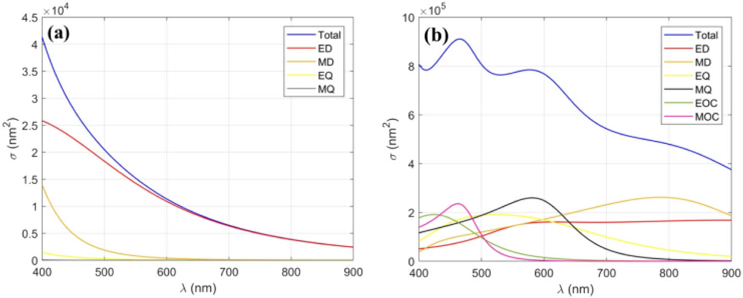
    Fig. 1. Free-space scattering cross sections of PS nanospheres (the refractive index is 1.6) with diameter being (a) 200 nm and (b) 500 nm. ED, electric dipole; MD, magnetic dipole; EQ, electric quadrupole; MQ, magnetic quadrupole; EOC, electric octupole; MOC, magnetic octupole.
    In-plane angle distribution of the SPP scattering intensity (TOTAL) by the PS nanospheres with diameter being (a) 200 nm and (b) 500 nm. Combination of the multipole contributions: ED, electric dipole; MD, magnetic dipole; EQ, electric quadrupole; MQ, magnetic quadrupole; EOC, electric octupole; MOC, magnetic octupole. The forward scattering corresponds to φ=0; for the backward scattering φ=π. The incident SPP’s frequency corresponds to the light with the wavelength of 600 nm in free space.
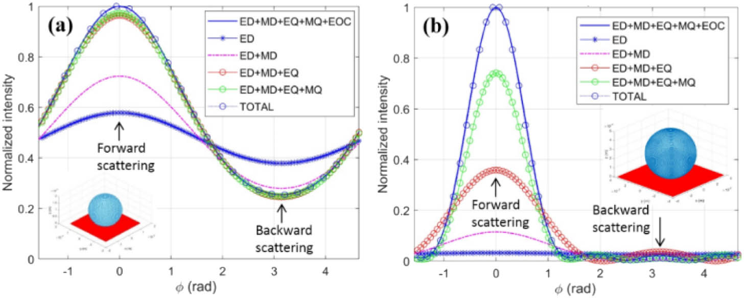
    Fig. 2. In-plane angle distribution of the SPP scattering intensity (TOTAL) by the PS nanospheres with diameter being (a) 200 nm and (b) 500 nm. Combination of the multipole contributions: ED, electric dipole; MD, magnetic dipole; EQ, electric quadrupole; MQ, magnetic quadrupole; EOC, electric octupole; MOC, magnetic octupole. The forward scattering corresponds to φ=0; for the backward scattering φ=π. The incident SPP’s frequency corresponds to the light with the wavelength of 600 nm in free space.
    SPP interacting with PS spheres of different diameters of 200 nm, 500 nm, and 1000 nm. SPP propagates along x axis with the wavevector k as shown in (a). (a) Simulated electric field amplitude distribution |E| with displacement vector, (b) simulated magnetic field amplitude distribution |H|, and (c) simulated surface charge distribution, simulated electric field component amplitude distribution. The incident SPP’s frequency corresponds to the light with the wavelength of 600 nm in free space.
    Fig. 3. SPP interacting with PS spheres of different diameters of 200 nm, 500 nm, and 1000 nm. SPP propagates along x axis with the wavevector k as shown in (a). (a) Simulated electric field amplitude distribution |E| with displacement vector, (b) simulated magnetic field amplitude distribution |H|, and (c) simulated surface charge distribution, simulated electric field component amplitude distribution. The incident SPP’s frequency corresponds to the light with the wavelength of 600 nm in free space.
    Electric field intensity distribution of scattered SPPs with particle diameters being (a) 200 nm, (b) 300 nm, (c) 500 nm, (d) 800 nm, and (e) 1 μm. The spatial frequency spectra of SPP scattering in k-space with particle diameters being (f) 200 nm, (g) 300 nm, (h) 500 nm, (i) 800 nm, and (j) 1 μm. The angular distribution of SPP scattering of single PS particle with diameters being (k) 200 nm, (l) 300 nm, (m) 500 nm, (n) 800 nm, and (o) 1 μm. The forward-to-backward scattering intensity ratios are 2.49, 11.13, 28.99, 37.78, and 50.26, respectively.
    Fig. 4. Electric field intensity distribution of scattered SPPs with particle diameters being (a) 200 nm, (b) 300 nm, (c) 500 nm, (d) 800 nm, and (e) 1 μm. The spatial frequency spectra of SPP scattering in k-space with particle diameters being (f) 200 nm, (g) 300 nm, (h) 500 nm, (i) 800 nm, and (j) 1 μm. The angular distribution of SPP scattering of single PS particle with diameters being (k) 200 nm, (l) 300 nm, (m) 500 nm, (n) 800 nm, and (o) 1 μm. The forward-to-backward scattering intensity ratios are 2.49, 11.13, 28.99, 37.78, and 50.26, respectively.
    Experimental setup of measurement to forward scattered SPPs.
    Fig. 5. Experimental setup of measurement to forward scattered SPPs.
    Simulated SPP electric field intensity distribution |E|2 at z=5 nm in real space of single PS nanospheres with diameters being (a) 200 nm, (b) 300 nm, (c) 500 nm, (d) 800 nm, and (e) 1 μm. k manifests the propagating direction of SPPs. Experimental real-space imaging to single PS nanospheres with diameters of (f) 200 nm, (g) 300 nm, (h) 500 nm, (i) 800 nm, and (j) 1 μm. Experimental k-space imaging to single PS nanospheres with diameters being (k) 200 nm, (l) 300 nm, (m) 500 nm, (n) 800 nm, and (o) 1 μm.
    Fig. 6. Simulated SPP electric field intensity distribution |E|2 at z=5  nm in real space of single PS nanospheres with diameters being (a) 200 nm, (b) 300 nm, (c) 500 nm, (d) 800 nm, and (e) 1 μm. k manifests the propagating direction of SPPs. Experimental real-space imaging to single PS nanospheres with diameters of (f) 200 nm, (g) 300 nm, (h) 500 nm, (i) 800 nm, and (j) 1 μm. Experimental k-space imaging to single PS nanospheres with diameters being (k) 200 nm, (l) 300 nm, (m) 500 nm, (n) 800 nm, and (o) 1 μm.
    Experimental results of SPP scattering intensity of single PS nanospheres with diameters of (a) 200 nm, (b) 300 nm, (c) 500 nm, (d) 800 nm, and (e) 1 μm in k-space. The corresponding angular radiation distribution of PS nanospheres with diameters being (f) 200 nm, (g) 300 nm, (h) 500 nm, (i) 800 nm, and (j) 1 μm; the forward-to-backward scattering intensity ratios are 10.27, 19.98, 35.83, 25.55, and 22.44, respectively. Approximately simulated results of scattered SPPs with particle diameters being (k) 200 nm, (l) 300 nm, (m) 500 nm, (n) 800 nm, and (o) 1 μm. Corresponding angular radiation distribution of particles with diameters being (p) 200 nm, (q) 300 nm, (r) 500 nm, (s) 800 nm, and (t) 1 μm; the forward-to-backward scattering intensity ratios are 6.59, 20.43, 38.53, 28.22, and 25.3, respectively.
    Fig. 7. Experimental results of SPP scattering intensity of single PS nanospheres with diameters of (a) 200 nm, (b) 300 nm, (c) 500 nm, (d) 800 nm, and (e) 1 μm in k-space. The corresponding angular radiation distribution of PS nanospheres with diameters being (f) 200 nm, (g) 300 nm, (h) 500 nm, (i) 800 nm, and (j) 1 μm; the forward-to-backward scattering intensity ratios are 10.27, 19.98, 35.83, 25.55, and 22.44, respectively. Approximately simulated results of scattered SPPs with particle diameters being (k) 200 nm, (l) 300 nm, (m) 500 nm, (n) 800 nm, and (o) 1 μm. Corresponding angular radiation distribution of particles with diameters being (p) 200 nm, (q) 300 nm, (r) 500 nm, (s) 800 nm, and (t) 1 μm; the forward-to-backward scattering intensity ratios are 6.59, 20.43, 38.53, 28.22, and 25.3, respectively.
    Simulated electric field component amplitude distribution (a) |Ex|, (b) |Ez|, and (c) simulated magnetic field component amplitude distribution |Hy| of single PS nanospheres at plane y=0 nm. Incident SPP’s frequency corresponds to the light with the wavelength of 600 nm in free space.
    Fig. 8. Simulated electric field component amplitude distribution (a) |Ex|, (b) |Ez|, and (c) simulated magnetic field component amplitude distribution |Hy| of single PS nanospheres at plane y=0  nm. Incident SPP’s frequency corresponds to the light with the wavelength of 600 nm in free space.
    (a) Real-space imaging of single 300 nm Au nanospheres. (b) k-space imaging subtracting launched SPPs. (c) Angular radiation distribution of scattered SPPs of single 300 nm Au nanospheres.
    Fig. 9. (a) Real-space imaging of single 300 nm Au nanospheres. (b) k-space imaging subtracting launched SPPs. (c) Angular radiation distribution of scattered SPPs of single 300 nm Au nanospheres.
    (a) Comparison of the forward-to-backward scattering intensity ratios among experiment, simulation, and approximately simulated results. (b) Comparison of the forward and backward scattering intensity of PS nanospheres between simulation and approximately simulated results. (c) Enlargement of the backward scattering of PS nanoparticle with diameter being 500 nm, 800 nm, and 1 μm in (b).
    Fig. 10. (a) Comparison of the forward-to-backward scattering intensity ratios among experiment, simulation, and approximately simulated results. (b) Comparison of the forward and backward scattering intensity of PS nanospheres between simulation and approximately simulated results. (c) Enlargement of the backward scattering of PS nanoparticle with diameter being 500 nm, 800 nm, and 1 μm in (b).
    Xuqing Sun, Hongyao Liu, Liwen Jiang, Ruxue Wei, Chang Wang, Xue Wang, Xiaojuan Sun, Fei Wang, Xinchao Lu, Andrey B. Evlyukhin, Chengjun Huang. Directional surface plasmon polariton scattering by single low-index dielectric nanoparticles: simulation and experiment[J]. Photonics Research, 2023, 11(5): 765
    Download Citation