
Hang Wang, Na Zhang, Shumin Li, Qinfei Ke, Zhengquan Li, Min Zhou. Metal-organic framework composites for energy conversion and storage[J]. Journal of Semiconductors, 2020, 41(9): 091707
- Journal of Semiconductors
- Vol. 41, Issue 9, 091707 (2020)
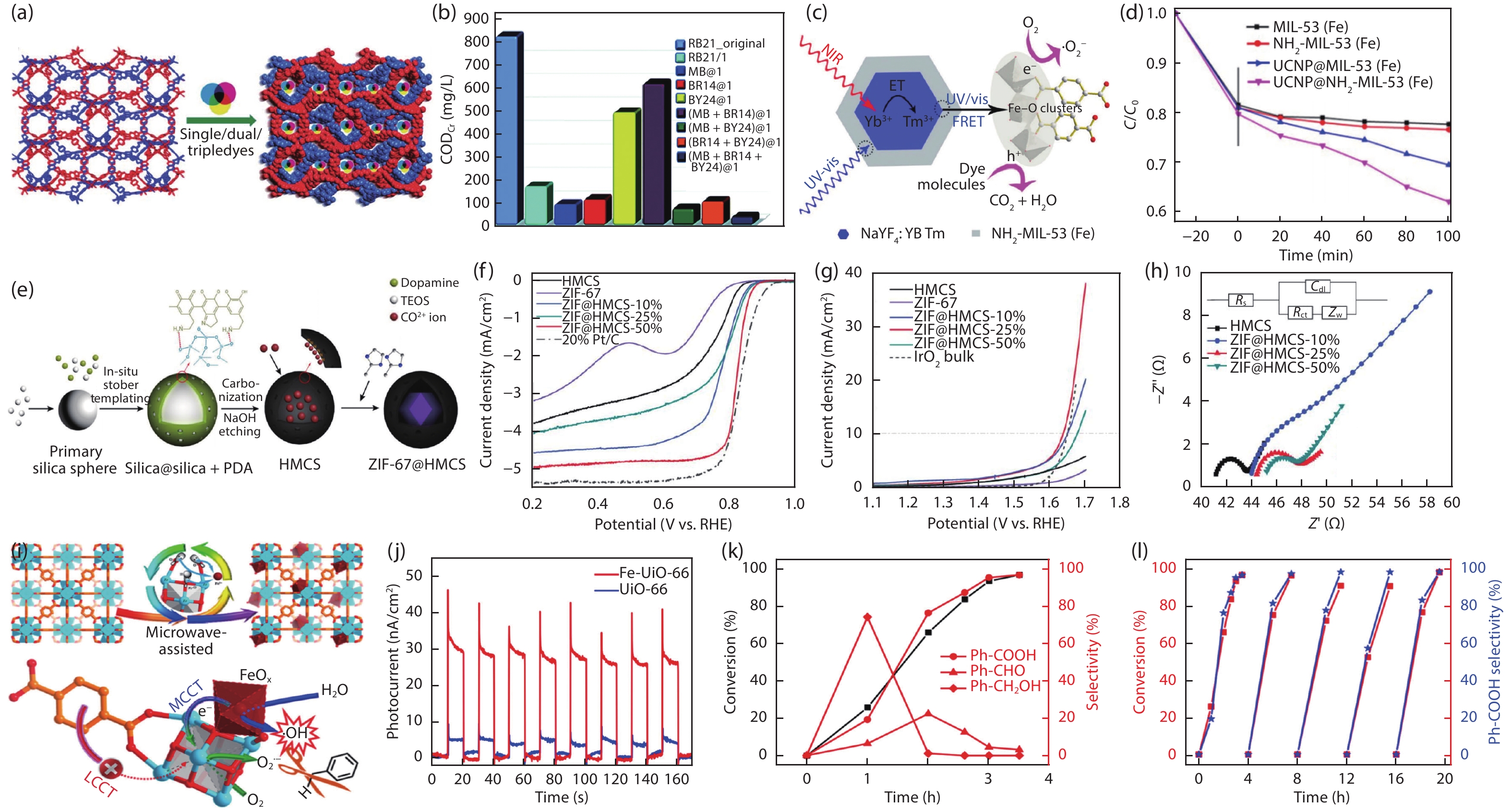
Fig. 1. (Color online) Design principle of MOF-based composites.
Fig. 1. (Color online) Typical examples of MOFs with assistance components for catalysis. (a) Schematic illustration of the cationic-dye@MOF. (b) The CODCr changes of RB21 before and after visible-light irradiation in the presence of several composite photocatalysts[21 ]. Copyright 2018, Royal Society of Chemistry. (c) Schematic illustration of the photocatalytic mechanism of the prepared composites. (d) Degradation profiles of RhB solution of samples activities under the NIR light[22 ]. Copyright 2017, American Chemical Society. (e) Schematic illustration of synthetic procedure for ZIF@HMCS. (f) The linear scan voltammogram (LSV) curves toward ORR of various samples. (g) LSV curves toward OER of various samples. (h) High frequency range electrochemical impedance spectroscopy (EIS) after fitting of various samples (inset: the corresponding equivalent circuit diagram)[27 ]. Copyright 2019, Oxford University Press. (i) Schematic illustration of Fe-UiO-66 and activation of stubborn C–H bond under visible light irradiation. (j) Photocurrent signals of UiO-66 and Fe-UiO-66. (k) Conversion/Selectivity-Time plot of toluene oxidation over Fe-UiO-66 under visible light irradiation. (l) Recycling tests of toluene oxidation over Fe-UiO-66 under optimized reaction conditions[28 ]. Copyright 2019, American Chemical Society.
Fig. 2. (Color online) Typical examples of MOFs with assistance components for supercapacitor. (a) Schematic diagram of Na-Zn-MOF/rGO. (b) The cyclic voltammograms (CV) collected of Na-Zn-MOF/rGO electrode. (c) A comparison of the GCD curves of a bare GCE, 1-GCE, 2-GCE and 3-GCE. (d) Cycling stability analysis of Na-Zn-MOF/rGO over 4000 cycles(the left and right insets show the first and last 25 cycles)[33 ]. Copyright 2019, Royal Society of Chemistry. (e) Schematic of synthesis procedure for CNF@MOF hybrid nanofibers. (f) Calculated areal capacitances of the device at different current densities within 0–0.7 V (blue curve) and 0–1.0 V (orange curve). (g) The CV curves at scan rate of 100 mV/s under different folding angles. (h) Cyclic performance and capacitance retention data of the device within 0–0.7 V (blue curve) and 0–1.0 V (orange curve)[36 ]. Copyright 2019, Wiley-VCH Verlag GmbH & Co. KGaA. (i) The schematic illustration of the strategy to synthesize CoNi-MOF/CFP. (j) CV curves of CoNi-MOF at a scan rate of 5, 10, and 25 mV/s. (k) Galvanostatic curves collected at a current density of 2, 4, 8, 16, and 32 A/g. (l) The cyclability of the capacitor over 5000 cycles [37 ]. Copyright 2019, American Chemical Society.
Fig. 3. (Color online) Typical examples of MOFs with assistance components for ion battery. (a) Schematic representation of the preparation process of Al-MOF/GO composite. (b) Proposed Li+ ions insertion-extraction process into or from Al-MOF. (c) Cycling performance and coulombic efficiency of Al-MOF and AMG at a current density of 100 mA/g. (d) The rate capability of Al-MOF and AMG[40 ]. Copyright 2019, Elsevier. (e) Synthesis of MOFs/CNT composite thin films. (f) The rate performances of S@HKUST-1/CNT electrode. (g) The cycling performances of S@HKUST-1/CNT, S@MOF-5/CNT and S@ZIF-8/CNT electrodes, respectively. (h) Nyquist plots of S@HKUST-1/CNT, S@MOF-5/CNT and S@ZIF-8/CNT electrodes, respectively[43 ]. Copyright 2017, Springer Nature. (i) Schematic illustration for fabricating a flexible MOF@PVDF-HFP membrane. (j) Schematic for Li-S batteries with different separators with a routine separator and MOF@PVDF-HFP separator. (k) The rate performance of Li–S cells with and without MOF@PVDF-HFP separators. (l) Comparison of the cycling performance of Li–S cells with and without MOF@PVDF-HFP separators[46 ]. Copyright 2018, Wiley-VCH Verlag GmbH & Co. KGaA.
Fig. 4. (Color online) Typical examples of MOFs with function components for catalysis. (a) Schematic illustration of the synthesis of NH2-UiO-66/TpPa-1-COF hybrid material. (b) The photocatalytic H2 evolution activities. (c) The photocatalytic stability of NH2-UiO-66/TpPa-1-COF (4 : 6). (d) Mechanism schematic of NH2-UiO-66/TpPa-1-COF (4 : 6) hybrid material[48 ]. Copyright 2018, Wiley-VCH Verlag GmbH & Co. KGaA. (e) Schematic illustrations for the synthesis of MAPbI 3@PCN-221. (f) The yields for CO2 reduction to CH4 and CO with PCN-221 and MAPbI3@PCN-221 as photocatalysts in the CO2-saturated ethyl acetate/water solution. (g) Steady-state photoluminescence spectra of various samples. (h) Time-resolved photoluminescence decays of various samples[52 ]. Copyright 2019, Wiley-VCH Verlag GmbH & Co. KGaA. (i) Schematic illustration showing the synthesis of Al-TCPP-Pt for photocatalytic hydrogen production. (j) Photocatalytic hydrogen production rates of various samples (inset: the calculated turnover frequency (TOF) of Al-TCPP-PtNPs and Al-TCPP-0.1Pt). (k) Recycling performance comparison for Al-TCPP-PtNPs and Al-TCPP-0.1Pt. (l) Calculated free energy diagram for photocatalytic H 2 production[53 ]. Copyright 2018, Wiley-VCH Verlag GmbH & Co. KGaA. (m) Schematic illustration of the synthesis process of Ti 3C2Tx -CoBDC hybrid for oxygen evolution reaction. (n) OER polarization curves of various electrodes. (o) Nyquist plots of the electrodes modified by IrO2, Ti3C2Tx , CoBDC, and Ti3C2Tx -CoBDC measured at a potential of 1.64 V vs RHE (Inset: Equivalent circuit used to fit the Nyquist plots). (p) Stability test of Ti3C2Tx -CoBDC-based electrode in comparison with the standard IrO2-based electrode, working at a constant potential of 1.64 V vs RHE for 10 000 s[56 ]. Copyright 2017, American Chemical Society.
Fig. 5. (Color online) Typical examples of MOFs with function components for catalysis. (a) Schematic illustration of PANI-ZIF-67. (b) Nyquist electrochemical impedance spectra of ZIF-67-CC and PANI-ZIF-67-CC. (c) Cyclic voltammograms collected of PANI-ZIF-67-CC electrode at different scan rate in 3 M KCl. (d) Cycling performance of the solid-state SC device measured at 0.1 mA/cm2 for 2000 cycles[58 ]. Copyright 2019, American Chemical Society. (e) Preparation illustration of Cu-CAT-NWAs/PPy. (f) Nyquist electrochemical impedance spectra of pristine PPy and various time-dependent Cu-CAT-NWAs/PPy based electrodes. (g) The galvanostatic charge-discharge curves at different current densities of Cu-CAT-NWAs/PPy electrode. (h) Cyclic stability over 5000 cycles under a scan rate of 100 mV/s for Cu-CAT-NWAs/PPy electrode[63 ]. Copyright 2020, Wiley-VCH Verlag GmbH & Co. KGaA. (i) Photographs of the solidstate SC device (inset: SEM image of MnO x -MHCF). (j) Cyclic voltammogram curves of MnOx -MHCF electrode at different scan rates in the range of 5–50 mV/s. (k) The galvanostatic charge-discharge curves of MnOx -MHCF electrode at current densities of 1.3–10.0 A/g. (l) Specific capacitances of MnOx -MHCF nanocube electrodes derived from the discharging curves at the current density of 1.3–10.0 A/g. (m) Cycling performance of the MnOx-MHCF nanocube electrode measured at the current density of 10.0 A/g for 10 000 cycles[64 ]. Copyright 2016, Wiley-VCH Verlag GmbH & Co. KGaA.
Fig. 6. (Color online) Typical examples of MOFs with function components for catalysis. (a) Schematic illustration of the synthetic process of CuS (x wt%)@Cu-BTC composites. (b) Cycling performance of Cu-BTC and the composites. (c) Rate capabilities and (d) impedance spectrum of CuS (70 wt%)@Cu-BTC[67 ]. Copyright 2019, Wiley-VCH Verlag GmbH & Co. KGaA. (e) Schematic illustration of LPS-UiO-66. (f) Cycling performance of LPS-UiO-66-containing cells. (g) Maximum capacity and (h) capacity after 100 cycles for various MOF composite cells [69 ]. Copyright 2019, American Chemical Society. (i) Scheme of MOFs/CNT composites with catalysis of the conversion of polysulfides as the separator coating materials for Li–S battery. (j) Impedance spectrum of symmetrical cells using different coating materials of CNT, Ce-MOF-1/CNT, and Ce-MOF-2/CNT. (k) Rate performance at various C-rates for the different separators. (l) Cyclic performance of cells with different separators at 1 C for 800 cycles[72 ]. Copyright 2019, American Chemical Society.
|
Table 1. MOF-based compositions for catalysis.
|
Table 2. MOF-based compositions for supercapacitor.
|
Table 3. The MOF-based compositions for ion battery.
|
Table 4. The component of the MOF-based compositions for catalysis.
|
Table 5. The component of the MOF-based compositions for supercapacitor.
|
Table 6. The component of the MOF-based compositions for battery.

Set citation alerts for the article
Please enter your email address
© Copyright 2018-2021 | Chinese Laser Press. All Rights Reserved 沪ICP备15018463号-20