Cunbao Lin, Shuhua Yan, Zhiguang Du, Guochao Wang, Chunhua Wei. Symmetrical short-period and high signal-to-noise ratio heterodyne grating interferometer[J]. Chinese Optics Letters, 2015, 13(10): 100501
Copy Citation Text
A symmetrical heterodyne grating interferometer with both a short period and high signal-to-noise ratio is proposed. It possesses good immunity to environmental disturbances and can simultaneously achieve high resolution and stability. The experimental results show that the standard deviation of 24.67 nm can be realized for the long range of 10 mm. The measurement resolution of better than 2 nm is achieved with the theoretical resolution of 12 pm. Additionally, system stability at less than is obtained in just over 10 min. The measurement errors, including cosine error, nonlinear error and non-common path error, are discussed as well.
Precision displacement measurement plays an important role in modern industry. With the capacity of environment insensitivity and its cost effectiveness compared with traditional laser interferometers, grating interferometers (GIs) have been widely used in variety of fields[1,2]. The symmetrical optical configurations are perhaps the most popular arrangements in GIs, since they usually exhibit better immunity to environmental disturbances. Meanwhile, since the achievable measurement resolution is considered to mainly depend on the period of the signal and the signal-to-noise ratio (SNR)[3,4], gratings with a short period and high diffraction efficiency are greatly favored in high-precision GIs. For one thing, the short period is beneficial to improving the resolution and depressing the errors[5]. For another, the high diffraction efficiency always leads to a high SNR, which is able to obtain higher accuracy for the phase measurement[4,6]. However, gratings with a shorter period often exhibit serious polarization dependency[7]. The different diffraction efficiencies between TE and TM polarization would severely decline the SNR of the measurement signals, and sometimes would even bring interpolation errors[8]. The GIs with both a short period and a high SNR would be attractive in practical applications.
Both homodyne- and the heterodyne-type GIs have been proposed for displacement measurement. With the introduction of a carrier, heterodyne grating interferometers (HGIs) overcome the direct current offset and the amplitude variation of the measurement signals that the homodyne type always encounters[9]. Lee et al. first proposed a HGI with subnanometric resolution[10]; then, they introduced the shearing interferometry into HGIs for long-range applications[11]. Wu et al. presented a HGI with a double-diffraction arrangement that can effectively compensate the head-to-scale error[5], then developed a common-path HGI with a Littrow configuration to further improve the resolution and stability[9]. Hsieh et al. proposed a HGI with a quasi-common-optical-path configuration[12]. Hsu et al. presented a HGI with holographic gratings and integrated it into a compact displacement sensor[13]. Although these HGIs often exhibit remarkable performance with specific merits, the one that simultaneously concentrates on the short period and high SNR has rarely been reported for displacement measurement.
In this Letter, we propose a symmetrical HGI with both a short period and high SNR. The short-period scale grating is especially utilized to decrease the signal period and improve the diffraction efficiency. Meanwhile, a half-wave plate (HWP) arrangement is adopted to enhance the SNR and the contrast of the measurement signals. With the simultaneous modification of the effects of the optical and the electronic systems, the overall performance of the HGI is expected to be effectively improved. In the remainder of this paper, the measurement principle of the proposed HGI is presented first. Then, the performance testing, including the long-range, short-range, and stability measurements, are discussed, including a comparison of the calibration equipment. Finally, the cosine error, nonlinear error, and non-common path (NCP) error of the HGI are discussed.
Sign up for Chinese Optics Letters TOC. Get the latest issue of Chinese Optics Letters delivered right to you!Sign up now
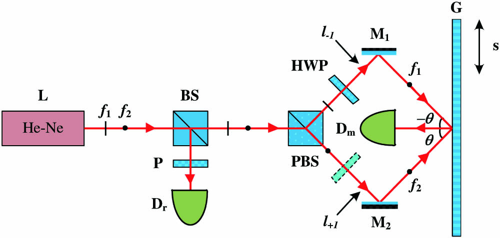
The schematic of the proposed HGI is shown in Fig. 1. A dual-frequency laser () emits two orthogonally linear polarizations, and , with the frequency of and , respectively. They are incident on a beam splitter and are divided into two parts, one for reference and the other for measurement. The reference beam passes through a polarizer () with a transmittance axis at 45°. Then, it is received by the photodetector , and the reference signal is generated. The measurement beam is incident on a polarizing beam splitter (PBS), and the two polarizations are separated. Then, one of the polarizations is changed into the other by a HWP with a transmittance axis at 45°. Both of the beams are reflected by the mirrors (), and are incident on the grating () at the first-order diffraction angle . The and the order diffraction beams overlap and they emit perpendicular to the grating surface. They are received by the photodetector , and the measurement signal is then generated.
Figure 1.Schematic of the optical configuration for the proposed HGI, BS: beam splitter.
According to the Jones matrix, the light emitting from the dual-frequency laser can be expressed as where and are the angular frequencies of the two polarizations, respectively. The reference signal that is received by the photodetector can be written as For the measurement signal, it would have a different expression if the HWP were placed on a different path. When the HWP is placed on the path of the polarization, the measurement signal can be written as Meanwhile, if the HWP is placed on the path of the polarization, the measurement signal can be expressed as where and denote the diffraction efficiencies of the grating for the and the polarizations, respectively. denotes the wave vector in air and is defined as , is the air refractive index, and represent the lengths of the two separate paths resulting from the NCP configuration, and and represent the phase shifts of the order diffraction beams varying with the grating’s movement. When the grating undergoes a displacement of , and can be obtained with where is the grating pitch. It can be seen from Eqs. (3) and (4) that the amplitude of the measurement signal is proportional to the diffraction efficiency of the grating. Since gratings often have different diffraction efficiencies for the and the polarizations, the place of the HWP should be deliberately chosen in the proposed HGIs. If the grating has a higher diffraction efficiency for the polarization, the HWP should be placed on the path to change the polarization into the polarization; otherwise, it should be placed on the path to change the polarization into the polarization. Then the polarization with the higher diffraction efficiency can be utilized, and the SNR of the measurement signal would also be enhanced.
After the optical signals are converted to the electronic signals, they are sent into a phasemeter or a lock-in amplifier, and the phase difference between the reference signal and the measurement signal can be measured as where and are the phase differences resulting from the NCP configuration and the grating movement, respectively. The result reveals that the NCP phase difference is mainly determined by the wave vector and the length difference of the two paths. With the symmetrical optical configurations, even though the errors resulting from the atmospheric inhomogeneity and thermal effect cannot be suppressed, the part owing to the uniform change of the air refractive index could be effectively decreased. If the NCP phase difference is assumed to be a constant and ignored, then the grating displacement can be obtained as
This equation reveals that the displacement is proportional to the measured phase difference and the grating pitch. When the short-period grating is utilized, the sensitivity would be enhanced and the errors would also be depressed. Then, the resolution and stability of the HGI would also be improved. Additionally, compared with other HGIs, with the cooperating utilization of the short-period scale grating and the HWP arrangement, the short period and high SNR would be simultaneously obtained. Then the effects of both the optical and the electronic systems would be improved. Therefore, the high resolution and stability are more likely to be achieved for the proposed HGI.
A dual-frequency laser (model: 5519A, Agilent Inc.) with a nominal vacuum wavelength of 632.991 nm was used as the light source, as shown in Fig. 2. All the optical components were mounted with on short pedestals to minimize the volume and enhance the steadiness[2]. A reflective holographic grating (model: GH25-12 V, Thorlabs Inc.) with a short period of 833 nm was utilized as the measurement scale. The diffraction efficiencies for the and the polarizations are 40% and 60% under the Littrow configuration, respectively. Therefore, the HWP is placed on the path to change the polarization into an polarization to improve the SNR of the measurement signal. The grating was fixed on a 15 μm-range piezoelectric stage (model: P-752.1CD, Physik Instrumente Inc.) with a specially designed mounting device. A motorized stage (model: KSA150-12-X, Zolix Inc.) with a range of 150 mm was also used for a long-range experiment. A laser interferometer (model: XL-80, Renishaw Inc.) with resolution of 1 nm was utilized to monitor the displacement of the stage. The detection signals were sent to the lock-in amplifier (model: SR830, Stanford Research Systems Inc.) and our homemade phasemeter to measure the phase difference. The system was constructed in a clean room on the first underground floor, and the optical layout was shielded by enclosures during the experiments.
Figure 2.Experimental setup of the optical system for the proposed HGI.
The long-range measurement capability of the proposed HGI was tested using millimeter-scale displacements. The motorized stage was used to move the grating, and a modified homemade phasemeter with resolution of 0.18°[14] was utilized to measure the phase difference. The motorized stage was set to make a round-trip movement ten times with a displacement of 10 mm. The actual displacement of the grating was monitored by the XL-80. Figure 3 shows the measurement results of the HGI and the XL-80. The different slopes between the first- and the second-half sections for the forward and the backward movements are attributed to the unequal moving speed of the motorized stage. The inset in Fig. 3 shows that a difference of about 1.2 μm is observed for the 10 mm displacement. This mainly results from the cosine error, which results from the discrepancy between the grating vector and the optical axis of the XL-80. We averaged the measurement results for ten seconds after the stage recovers and stablizes; the averages of the HGI and the XL-80 are listed in Table 1. The ratios between the HGI and the XL-80 are calculated as well. Since the movement of the grating was taken at the same position as the KSA150-12-X stage, the cosine errors are assumed to be the same for all ten measurements. Then, the mean value of 1.000119 for these ratios is calculated and is set to be the correction factor for the cosine errors. The residual errors after the cosine errors have been removed using the correction factor[15] are exhibited in Table 1. It reveals that the residual error for the 10 mm displacement is within , and the standard deviation is calculated to be 24.67 nm.
HGI (mm)
XL-80 (mm)
Ratio
Residual Error (nm)
1st
10.000710
9.999553
1.000116
−32.95
2nd
10.000657
9.999463
1.000120
4.07
3rd
10.000142
9.998967
1.000118
−14.88
4th
10.000943
9.999773
1.000117
−19.97
5th
10.000125
9.998907
1.000122
28.13
6th
10.000241
9.999100
1.000114
−48.89
7th
10.000400
9.999201
1.000120
9.10
8th
10.000747
9.999537
1.000121
20.06
9th
10.000079
9.998900
1.000118
−10.87
10th
10.000453
9.999236
1.000122
27.09
Table 1. Measurement Results and Residual Errors of the HGI and the XL-80 for the 10 mm Displacement
The short-range measurement capability of the proposed HGI was tested with micron and nanometer scale displacements. The P-752.1CD piezoelectric stage with a resolution of 0.1 nm was used to provide the movement of the grating. In combination with frequency down-conversion technology, the SR830 lock-in amplifier with a phase resolution of 0.01° was utilized to measure the phase difference. The theoretical resolution of the HGI corresponding to 0.01° phase resolution is 12 pm. First, the P-752.1CD stage was set to move in a sinusoidal displacement with an amplitude of 10 μm. Figure 4 shows the measurement result of the HGI, which is quite close to the ideal sinusoidal wave. The peak-to-peak value of the measured sinusoidal displacement is 10.015 μm, which is a little bigger than the set value of 10 μm. This discrepancy is considered to be mainly from the cosine error. Then, the P-752.1CD stage was set to make a 10 nm-step movement in 2 nm steps. Both the forward and backward movements were conducted to simultaneously test the repeatability of the HGI. Figure 5 shows the measurement result of the HGI for the round-trip step movement. It illustrates that the 2 nm step movement can be clearly detected by the HGI, which means the measurement resolution is better than 2 nm. With the definition of repeatability given in Ref. [16], the repeatability of the proposed HGI is calculated to be about 0.25 nm.
Figure 4.Measurement result of the sinusoidal movement with an amplitude of 10 μm.
The stability of the proposed HGI was then tested and compared with that of the XL-80 laser interferometer. The P-752.1CD stage was turned off electrically to remove the piezoelectric deformation. The XL-80 laser interferometer was fixed next to the HGI, and they were shielded into the same space. We simultaneously initialized these two instruments and set them to detect the displacement variation for ten minutes. Figure 6 shows the stability measurement results for the HGI and the XL-80. It indicates that the fluctuation of the HGI is within and no evident drift is observed, whereas the stability of the XL-80 is about 20 nm and suffers from drift. The results reveal that the HGI has better immunity to the drift effect than the XL-80. The symmetrical configuration and miniaturized volume are considered to be the dominant reasons for the good stability compared with the laser interferometer.
Figure 6.Stability measurement results for the HGI and the XL-80 in ten minutes.
Among these error sources for the proposed HGI, the cosine error perhaps is the most important one. It mainly results from the misalignment of the optical components. As illustrated in the above measurement results, the relative deviations are about 15 nm and 1.2 μm for the short- and long-range displacement measurements, respectively. It is consistent with the theoretical derivation, since the cosine error is directly proportional to the measurement displacement. These errors can be greatly declined with the proper alignment in displacement measurement[17].
The nonlinear error is also a dominant error source for the proposed HGI. The nonorthogonality and ellipticity of the dual-frequency laser, the imperfect extinction ratio of the PBS, and the inaccurate azimuth angle of the HWP, all result in the frequency mixing, polarization mixing, and polarization-frequency mixing errors. Based on our previous analysis[18], with the nonorthogonal angle, the ellipicity, the extinction ratio, and the inaccurate azimuth angle of about 1°, 0.08, 0.01%, and 1° in our system, the frequency mixing, polarization mixing, and polarization-frequency mixing errors are estimated to be 1.15, 0.01, and 0.42 nm, respectively. Therefore, the maximum nonlinear error in our system is about 1.58 nm. The passive approach can be applied to compensate for these nonlinear errors[19].
The NCP error, which results from the non-overlap of the two optical paths and , is another error for the proposed HGI. Since the symmetrical optical configuration is utilized in our HGI, the difference between and was measured to be less than 5 mm. The air refractive index was also monitored by an air sensor (model: E1738A, Agilent Inc.) with the temperature, humidity, and pressure resolutions being 0.01°, 1%, and 10 Pa, respectively. The total air temperature, humidity, and pressure changes were detected to be 0.05°, 3%, and 90 Pa within three hours. The variation of the air refractive index was then calculated with the modified Edlén equation[20], and is shown in Fig. 7. It reveals that the variations of the air refractive index are within in 3 h and within in 10 min. If the gradient of the air refractive index is ignored, the variation of the displacement would be about 0.5 nm within 10 min. Since the stability of the proposed HGI is about , the remaining errors resulting from the material thermal expansion, background vibration, and electronics noises also need to be analyzed to further improve the performance of the HGI.
Figure 7.Variation of the air refractive index in 3 h.
In conclusion, we propose a symmetrical HGI with both a short period and a high SNR. The resolution and stability are effectively improved with the specially designed optical configuration. The experimental results show that the proposed HGI can simultaneously achieve nanometer resolution and millimeter range, which means it is appropriate for both high-resolution and long-range displacement measurements. Additionally, the stability of the HGI is tested, and it exhibits better immunity than the laser interferometer. It reveals that it is more suitable for applications in the ordinary environment. The cosine error, nonlinear error, and NCP error are also analyzed for the proposed HGI. Our future work will mainly involve compensating for the measurement errors to further improve the performance of the HGI.
References
[1] Y. Fu, J. Yang, Z. Wang, H. Wu. Chin. Opt. Lett., 12, 121101(2014).
Cunbao Lin, Shuhua Yan, Zhiguang Du, Guochao Wang, Chunhua Wei. Symmetrical short-period and high signal-to-noise ratio heterodyne grating interferometer[J]. Chinese Optics Letters, 2015, 13(10): 100501