School of Information Science & Technology, Center for Information Photonics & Communications, Southwest Jiaotong University, Chengdu 610031, Sichuan , China
Exploiting microwave photonic (MWP) techniques to generate and distribute high-frequency millimeter-wave (mm-wave) signals, termed mm-wave radio over fiber (m-RoF) signals, holds considerable potential for achieving high-density and high-capacity fifth-generation and beyond networks. Herein, we experimentally validate a broadband m-RoF uplink fronthaul transmission system using the MWP downconversion concept, which comprises receiving and processing radio-frequency (RF) signals in the unlicensed V-band at around 60 GHz. The proposed system harnesses the simple cascaded modulator topology, in which an ultrawideband off-the-shelf Mach–Zehnder modulator (MZM) renders a simple-structured remote radio head by directly encoding the broadband 60 GHz uplink RF signal into the optical carrier. The nonlinear transfer function of another MZM at the center unit is explored to achieve subharmonic downconversion using cost-effective low-frequency local oscillator signals. Based on proof-of-concept experiments, mm-wave four quadrature amplitude modulation orthogonal frequency-division multiplexing signals centered at frequencies ranging from 51 GHz to 70 GHz are successfully downconverted into signals at the intermediate frequency (IF) of 1.4 GHz. In the case of 1.2 m mm-wave, free-space, and 5 km m-RoF transmissions, the obtained IF signals with a total bandwidth of 2.4 GHz achieve a bit-to-error ratio performance lower than the 7% hard-decision forward error correction limit of 3.8 × 10⁻³. A gross bit rate of 10 Gbit/s can be achieved over a total spectrum of up to 10 GHz, which fully covers the globally unlicensed V-band of 57-66 GHz.
1 Introduction
Fueled by the explosive growth in mobile data traffic,the 1000-fold increase in capacity compared to legacy networks is one of the key performance indicators for the fifth-generation and beyond(5G/B5G)networks[1]. To meet such a high aim,migration to a high millimeter-wave(mm-wave)frequency band for harvesting the huge available bandwidth(e.g.,the 7-9 GHz-wide unlicensed spectrum located in the V-band around 60 GHz)and ultradense small-cell network to improve spectral efficiency have been widely acknowledged as key enabling technologies[2]. Furthermore,the centralized radio access network(C-RAN)architecture has been extensively explored to reach its promising potential of efficiently supporting the massive densification of small cells[3-4]. Nonetheless,the real-world deployment of ultradense C-RAN incorporating mm-wave technologies is typically hampered by the capacity constraints of fronthaul links using bandwidth-inefficient digital transmission schemes as well as the maintenance and operational costs of massively distributed mm-wave remote radio heads(RRHs)with costly analog-to-digital/digital-to-analog converter(ADC/DAC)and high-frequency radio-frequency(RF)front-end modules[5].
Fortunately,using the microwave photonic(MWP)techniques to generate and distribute the mm-wave signals,i.e.,mm-wave radio over fiber(m-RoF)paves a new avenue for addressing the aforementioned challenges[6-18]. First,MWP mm-wave generations employing schemes,such as optical heterodyne detection[6-7],optoelectronic oscillator[8],and cascaded modulators[9],offer a compelling alternative to overcome the limitations of traditional electronic approaches in terms of cost,complexity,and bandwidth. Furthermore,m-RoF allows for the transparent and low-loss transmissions of mm-wave radio signals generated at the center unit(CU)to RRH. Due to the avoidance of digitization,this enables a critical benefit of high bandwidth efficiency for large capacity fronthauling[10-11]. It also shifts the ADC/DAC and high-frequency RF front-end functions in RRH to CU,resulting in a much simpler and lower-cost version of RRH that only requires electrical-to-optical(E/O)/optical-to-electrical optic(O/E)conversion and RF antennas[12]. However,the majority of reported m-RoF fronthaul systems merely discuss the downlink transmissions[9,13-17]. When considering high-frequency(typically 60 GHz)m-RoF uplink transmission,its cost and complexity superiorities are jeopardized by the inclusion of a high-frequency electrical mixer and local oscillator(LO)source in RRH for down-converting RF signals to a low intermediate frequency(IF)band[11,18].
Meanwhile,using high-speed E/O devices to directly convert mm-wave RF signals to the optical domain for uplink delivery would result in a significant reduction in complexity,cost,and bulkiness of RRHs because no high-frequency RF front-end components are required. Thus,in Ref.[19]and Ref.[20],specifically fabricated ultrabroadband plasmonic phase and Mach–Zehnder modulators(MZM)are reaped in RRH to directly load optical carriers with the 60 GHz and 288.5 GHz RF signals. Then,to avoid using a high-speed photodetector and an expensive electronic mixer for recovering and demodulating mm-wave signals in CU,direct photonic downconversion leveraging the optical coherent receiver is proposed in Ref.[19]and Ref.[20],which requires an additional free-running laser and thus adds cost,complexity,and phase noise. Furthermore,no fiber transmissions are demonstrated. The coherent two-tone optical signal is generated in RRH to carry 38 GHz mm-wave signals to CU over the 20 km fiber link as shown in Ref.[21]. The beating between modulated and unmodulated optical tones results in direct photonic downconversion. Nonetheless,due to the greatly increased complexity imposed by the dual-parallel MZM for generating a two-tone optical signal and extra passive and active components to form two separate optical paths,this scheme is incompatible with the goal of ultracompact RRH. Furthermore,custom-made electro-optic modulators are required.
Alternatively,MWP downconversion using the cascaded modulator topology raises the possibility of realizing both a simple-structured RRH and the low-cost ultrawideband photonic downconversion capability[21-25]. The RF and LO modulations of the identical optical carrier are performed separately at RRH and CU in this architecture,which has a simple structure and excellent coherence in the optical domain. However,the majority of reported works are limited in processing narrow-band single-tone RF signals below 40 GHz. Pioneering cascaded photonic downconversion schemes using the electro-absorption modulators(EAMs)has achieved an operating frequency band around 60 GHz. Regardless,the EAM requires temperature feedback control,and its high insertion loss and poor modulation efficiency result in a limited data rate(<1 Gbit/s)in experimental demonstrations[26-27]. Furthermore,few of them thoroughly consider both the fiber and wireless transmissions. Consequently,the critical benefits of MWP technology covering ultrawideband and low frequency-dependent transmission loss have not been fully exploited.
Herein,we propose and demonstrate an experimentally validated broadband m-RoF uplink fronthaul transmission system based on the cascaded microwave photonic downconversion topology,with a focus on the 60 GHz band featuring over 7 GHz unlicensed spectrum. A commercially available off-the-shelf MZM of ultrawideband is utilized at RRH to implement E/O conversion for the uplink broadband mm-wave signals at carrier frequencies ranging from 51 GHz to 70 GHz and line rates up to 10 Gbit/s. At CU,the modulation nonlinearity of followed MZM is harvested for low-cost photonic subharmonic downconversion. The performance of the downconversion system is experimentally demonstrated by successfully receiving the four quadrature amplitude modulation(4-QAM)orthogonal frequency-division multiplexing(OFDM)encoded mm-wave signals over the 1.2 m free-space and 5 km fiber transmission distances. This research has the potential to accelerate the integration of MWP technologies into future 5G/B5G ultradense mm-wave C-RANs by providing unique economic and implementary benefits covering simplified RRHs,low-loss,and high-capacity mm-wave fronthauling as well as cost-effective processing of high-frequency and large-bandwidth signals.
2 Principle
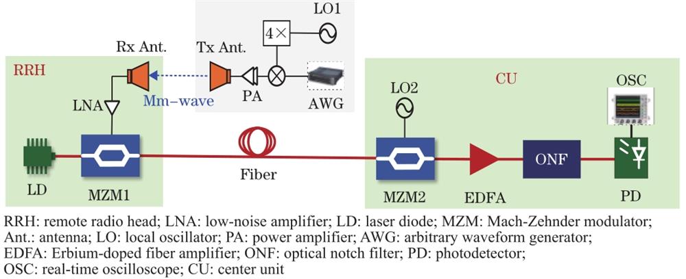
Figure 1 depicts the schematic of the proposed m-RoF uplink transmission system. The simple-structured RRH comprises a laser diode(LD),an MZM,and a receiving antenna incorporated with an electrical low-noise amplifier(LNA). The received mm-wave signal at the output of LNA is applied to MZM1 after compensating for free-space transmission loss. An mm-wave signal directly modulates the continuous-wave optical carrier emitted from an LD through MZM1. The output electrical field of MZM1 can be expressed as follows assuming a single-tone uplink mm-wave signal with a center(angular)frequency.
,
Figure 1.Schematic of m-RoF uplink fronthaul system using cascaded microwave photonic downconversion topology
where and are the angular frequency and power of optical carrier,respectively. is the phase difference between the two arms of MZM1. denotes modulation index. is proportional to the amplitude of the mm-wave signal and and are the half-wave voltage and insertion loss of MZM1,respectively. When MZM1 is biased at the quadrature point(i.e.,)for normal intensity modulation(IM)and under the condition of small-signal modulation,Eq.(1) can be rewritten as
,
where is the nth-order Bessel function of the first kind and is an integer. Afterward,this IM lightwave is sent to CU through a segment of the fiber link. At CU,it is injected into MZM2,of which the RF port is driven by LO2. Consequently,the uplink optical carrier loaded with the mm-wave signal is remodulated by LO2 in MZM2. When LO2 is centered at ,the output of MZM2 can be derived as
,
where stands for the fiber transmission loss and ,which is dependent on the amplitude of LO signal(i.e.,)and half-voltage of MZM2(i.e.,). represents the biasing point of MZM2. Its value is adjusted to be zero for biasing MZM2 at the maximum transmission point,suppressing first-order sidebands and generating second-order sidebands for subharmonic downconversion. Following that,an Erbium-doped amplifier(EDFA)and an optical notch filter(ONF)are added to MZM2 to remove the optical carrier. The suppression of the optical carrier improves conversion efficiency with PD of limited saturated input optical power of PD[28]. By ignoring the sidebands exceeding second-order,the optical signal before PD is
,
where G denotes the gain of EDFA and ONF. Thus,after the square-law detection in a low-speed PD,the generated photocurrent can be described as
In this case,we only consider the mixing term at IF frequency,i.e.,,and represents the responsivity of PD. As shown in Eq.(5),subharmonic downconversion of the received mm-wave signal is possible with the frequency-doubling of LO2 and low-speed PD,significantly lowering the receiver’s cost. Consequently,in terms of simplified RRH,low-loss delivery,and low-cost processing of the wideband mm-wave signal,this cascaded microwave photonic downconversion topology can be expected as an advantageous solution for mm-wave uplink fronthaul transmission.
3 Experiments and discussions
Experiments are performed using the setup shown in Fig. 1. The 1550 nm optical carrier with a power of 10 dBm is emitted from a tunable LD(Teraxion PS-TNL)at the RRH. To directly load the mm-wave signal onto the optical carrier,an off-the-shelf ultrawideband MZM with a 3 dB bandwidth up to 65 GHz(EOSPACE AX-0MVS-65-PFA)is used. The uplink 60 GHz mm-wave signal for proof-of-concept verification is synthesized through the electrical up-conversion of the IF signal from an arbitrary waveform generator(AWG Keysight M9502A)running at 32 GSa/s. The LO signal for frequency up-conversion is achieved through the electrical frequency-quadrupling of the single-tone RF signal(i.e.,LO1)generated from a microwave generator(MG,Anritsu MG3694B). The 1.2 m mm-wave free-space transmission is established by an electrical power amplifier(PA),a pair of horn antennas,and an LNA operating at the frequency band of 50-75 GHz(Fig. 1).
The fiber transmission distance between RRH and CU is set as 5 km. Because of the subharmonic downconversion,another single-tone RF signal(i.e.,LO2)from the second MG(Anritisu MG3694C)is applied to MZM2 at the CU,with a 3 dB bandwidth below 40 GHz(Sumitomo T.MXH1.5). After being boosted by the EDFA,the output of MZM2 is sent to a commercially available waveshaper(WS,Finisar 4000S)for suppressing the optical carrier through notch filtering. A 15 GHz PD is employed for optical-electrical conversion,resulting in a downconverted IF signal,of which the electrical spectrum and temporal waveform are observed by the electrical spectrum analyzer(ESA)and real-time oscilloscope(OSC).
First,the RF performance metrics of the downconversion system are defined without considering wireless and fiber transmissions. Fig. 2 shows the optical spectra at the output of MZM1 and MZM2 when the frequencies of single-tone LO1 and LO2 are set as 15 GHz and 31.5 GHz,respectively. As shown in Fig. 2(a),the 60 GHz mm-wave signal produced by frequency-quadrupling of the 15 GHz LO1 is directly encoded onto the optical carrier through MZM1. In addition,Fig. 2(a)shows a high modulation efficiency,which is beneficial for obtaining a high output power for the recovered RF signal. Following MZM2,second-order sidebands induced by the 31.5 GHz LO2 are generated and an over 23 dB suppression ratio for the first-order sidebands is observed[Fig. 2(b)]. The optical spectrum after WS is shown in Fig. 3(a),with the optical carrier band significantly suppressed to improve conversion efficiency. Thus,when the input optical power of PD is around -0.7 dBm,the measured electrical spectrum of the 3 GHz IF signal is shown in Fig. 3(b),which is generated from the subtractive mixing of 60 GHz mm-wave signal and the 63 GHz second-harmonics of LO2.
Figure 2.Measured optical spectra at the output. (a) MZM1; (b) MZM2
Furthermore,the conversion efficiency of the proposed downconversion system for input mm-wave signals in the frequency range from 50 GHz to 72 GHz is investigated and shown in Fig. 4. Due to the limited operation frequency of the available measurement devices(e.g.,ESA),the conversion efficiency here is alternatively defined as the ratio between output IF power to the input power of LO1,which experiences a conversion loss induced by the active frequency multiplier for generating the mm-wave signal. The frequency of LO2 is adjusted accordingly to keep the downconverted IF signal at 3 GHz and the input optical power of PD is fixed at -0.7 dBm. As shown in Fig. 4,in the frequency range of operation from 50 GHz to 72 GHz,the fluctuation of the conversion efficiency is less than 6 dB,which accords with output power versus frequency characteristic of the used active frequency multiplexer[29].
Figure 4.Measured conversion efficiency versus different frequencies of input mm-wave signals
The case of the broadband uplink wireless mm-wave signal is then investigated. A high-speed AWG generates a 1 GHz bandwidth 4-QAM OFDM centered at 0.7,which is then up-converted to the 60 GHz band using an electrical mixer and the frequency-quadrupling of LO1. Afterward,a V-band PA integrated with a horn antenna emits a 60 GHz broadband mm-wave signal into free space. Following the 1.2 m free-space delivery,another horn antenna at RRH is equipped to receive the mm-wave signal and it sends it to MZM1 through the LNA. The downconverted broadband IF signal at the output of PD is measured and shown in Fig. 5(a)when the fiber link between MZM1 and MZM2 is 5 km long and the frequency of LO2 is set to 30.7 GHz. Because of the analog double-sideband modulation of the mm-wave carrier for frequency up-conversion,this IF signal has a total bandwidth of 2.4 GHz. Finally,the temporal waveform of the generated IF signal is digitized by a real-time OSC with a sampling rate of 40 GSa/s. Following that,off-line digital signal processing for signal demodulation is performed to evaluate its performance. As shown in Fig. 5(b),the demodulated signal has a clear constellation diagram,indicating a good bit-to-error(BER)value of 1.53×10⁻¹⁰. The BER is derived from the calculated root-mean-square error-vector-magnitude(EVM)[30]. The 4-QAM modulation format and 5 km fiber length are only for proof-of-concept experimental demonstrations. Our system can be expected to support a higher-order modulation format and longer transmission distance based on the achieved BER performance margin shown in Fig. 6[31].
Figure 5.Experimental results. (a) Measured electrical spectrum of downconverted broadband IF signal at 1.4 GHz after 1.2 m free-space and 5 km fiber transmissions; (b) constellation diagrams of the demodulated signal; calculated (c) EVM and (d) SNR for subcarriers
Figure 6.Experimental results. (a) BER versus different center frequencies of uplink mm-wave signal; (b) BER as a function of received optical power for 5 km fiber and back-to-back transmissions
Furthermore,the center frequency of the uplink mm-wave signal is varied over the frequency range from 51 GHz to 70 GHz under the identical 1 GHz bandwidth 4-QAM OFDM signal from AWG. The frequency of LO2 is thus tuned to achieve a fixed 1.4 GHz center frequency for the downconverted IF signal. Thus,the BER performance of demodulated IF signal versus different center frequencies of uplink mm-wave signals is shown in Fig. 6(a). The system can achieve a BER performance below the 7% hard-decision forward error correction limit,i.e.,3.8×10-3,within the operating frequency range of 51-70 GHz. Nonetheless,there is a significant fluctuation of BER value over the operating frequency range,which is highly related to the unflat frequency responses of used high-frequency electrical functional components covering the active mixer,amplifier,and multiplier. Furthermore,in Fig. 6(b),we demonstrate the BER performance of the system by adjusting the received optical power before PD for back-to-back and 5 km fiber transmissions using the same free-space transmission distance and 60 GHz uplink mm-wave signal. According to Fig. 6(b),the power penalty to meet the BER threshold of 3.8 × 10⁻³ is around 1 dB for the 5 km fiber transmission.
Higher data-rate transmissions scenarios are also experimentally validated. The bandwidth of the 4-QAM OFDM IF signal from AWG increases to 3 GHz and 5 GHz,corresponding to gross bit rates of 6 Gbit/s and 10 Gbit/s,respectively. Its frequency up-converted version has a center frequency of 61 GHz. After the delivery over the 1.2 m free-space and 5 km fiber links and microwave photonic downconversion using LO2,Figs. 7(a)and(b)show the measured electrical spectra of downconverted IF signals centered at 8 GHz and 10 GHz. Figs. 7(c)and(d)accordingly display the constellation diagrams of demodulated signals,showing BER values of 1.05 × 10⁻⁷ and 5.77 ×10⁻⁵ below the 3.8 × 10⁻³ limit for 6 Gbit/s and 10 Gbit/s bit rates. Furthermore,the 10 Gbit/s mm-wave signal centered at 61 GHz has a >10 GHz total double-sideband bandwidth,which fully occupies the globally unlicensed 60 GHz band of 57-66 GHz.
Figure 7.Measured electrical spectra of downconverted IF signals with (a) 3 GHz and (b) 5 GHz bandwidth 4-QAM OFDM signals; constellation diagrams of the demodulated signals with (c) 3 GHz and (d) 5 GHz bandwidth 4-QAM OFDM signals
We have proposed and experimentally demonstrated a cascaded microwave photonic downconversion solution for the broadband V-band m-RoF uplink transmission. The proposed uplink transmission system differs from others in that it directly converts the 60 GHz mm-wave signal to the optical domain before delivering and processing it using the microwave photonic technologies. Based on the experimental results,a commercially available off-the-shelf MZM can enable such a system to operate in a frequency band of 50-72 GHz. The 1.2 m free-space and 5 km m-RoF links are capable of transmitting data at rates of up to 10 Gbit/s. The proposed uplink transmission system features ultrasimplified RRH,low-loss and high-capacity mm-wave fronthauling,and cost-effective mm-wave signal processing,which renders it potentially attractive for deployment in the future ultradense mm-wave C-RAN.
The Author Email: Zhang Hui (lipeixuan@swjtu.edu.cn), Li Peixuan (lipeixuan@swjtu.edu.cn), Zou Xihua (lipeixuan@swjtu.edu.cn), Bai Wenlin (lipeixuan@swjtu.edu.cn), Pan Wei (lipeixuan@swjtu.edu.cn), Yan Lianshan (lipeixuan@swjtu.edu.cn)