• Laser & Optoelectronics Progress
  • Vol. 58, Issue 22, 2212003 (2021)
Zhaoxu Wang1、2, Yanjun Fu1、2、*, Ye Li1、2, Kejun Zhong1、2, and Wei Bao1、2
Author Affiliations
  • 1Key Laboratory of Nondestructive Testing Technology, Ministry of Education, Nanchang Hangkong University, Nanchang, Jiangxi 330063, China
  • 2School of Measuring and Optical Engineering, Nanchang Hangkong University, Nanchang, Jiangxi 330063, China
  • show less
    DOI: 10.3788/LOP202158.2212003 Cite this Article Set citation alerts
    Zhaoxu Wang, Yanjun Fu, Ye Li, Kejun Zhong, Wei Bao. Calibration Method for Line Structured Light Measurement System Based on Vanishing Point[J]. Laser & Optoelectronics Progress, 2021, 58(22): 2212003 Copy Citation Text show less
    Model of line structured light measurement
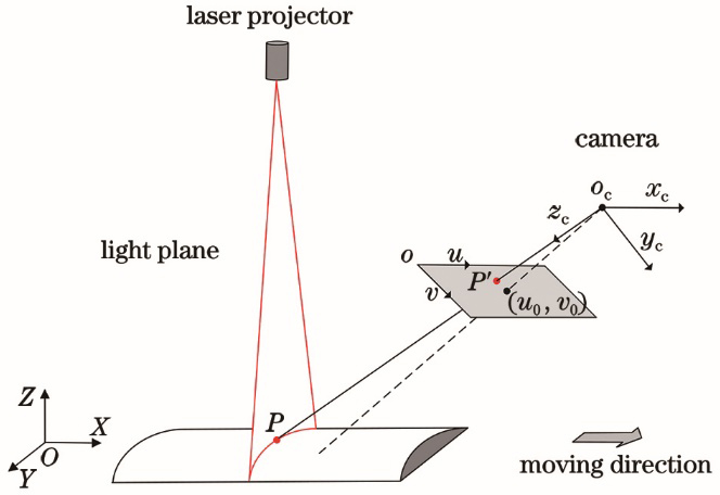
    Fig. 1. Model of line structured light measurement
    Model of one-dimensional direction calibration
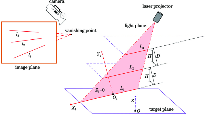
    Fig. 2. Model of one-dimensional direction calibration
    Position determination of world coordinate system
    Fig. 3. Position determination of world coordinate system
    Structure of experimental setup
    Fig. 4. Structure of experimental setup
    Influence of SNR on slope of feature strip
    Fig. 5. Influence of SNR on slope of feature strip
    Influence of SNR on calibration error
    Fig. 6. Influence of SNR on calibration error
    Calibrated images processing. (a)--(c) Original images; (d)--(f) processed images
    Fig. 7. Calibrated images processing. (a)--(c) Original images; (d)--(f) processed images
    Measurement of standard step block. (a) Object picture; (b) measured point clouds; (c) wrapped result
    Fig. 8. Measurement of standard step block. (a) Object picture; (b) measured point clouds; (c) wrapped result
    Measured height corresponding to 23rd stripe
    Fig. 9. Measured height corresponding to 23rd stripe
    Comparison of RMSE
    Fig. 10. Comparison of RMSE
    Measurement of sphere cover. (a) Object picture; (b) measured point clouds; (c) wrapped result
    Fig. 11. Measurement of sphere cover. (a) Object picture; (b) measured point clouds; (c) wrapped result
    Diagram of deviation distribution
    Fig. 12. Diagram of deviation distribution
    Comparison of absolute error
    Fig. 13. Comparison of absolute error
    Measurement of complex models. (a)--(d) Object models; (e)--(h) measured point clouds; (i)--(l) wrapped results
    Fig. 14. Measurement of complex models. (a)--(d) Object models; (e)--(h) measured point clouds; (i)--(l) wrapped results
    DirectionIef
    X-direction1.7562-0.0489-0.0354
    Y-direction0.21790.03370.0270
    Z-direction1.7925-0.0752-0.0604
    Table 1. Calibration results in three dimensions
    ParameterStep1Step2Step3Step4Step5
    Standard thickness5.001210.003615.002820.003425.0021
    Maximum error0.07130.06820.06570.07820.0853
    Minimum error0.00360.00450.00620.00680.0073
    RMSE0.03250.03040.03590.03360.0298
    Table 2. RMSE analysis unit: mm
    ParameterPosition1Position2Position3Position4Position5
    Actual diameter5.0022
    Fitted diameter5.02965.03375.03305.03165.0365
    Absolute error0.02740.03150.03080.02940.0343
    MAE0.0306
    Table 3. MAE analysis unit: mm
    Zhaoxu Wang, Yanjun Fu, Ye Li, Kejun Zhong, Wei Bao. Calibration Method for Line Structured Light Measurement System Based on Vanishing Point[J]. Laser & Optoelectronics Progress, 2021, 58(22): 2212003
    Download Citation