• Laser & Optoelectronics Progress
  • Vol. 58, Issue 21, 2112003 (2021)
Qiming Sheng1, Gang Zheng2、*, Xiongxing Zhang2, Yuan Han1, Yuan Guo2, and Mengdi Nie2
Author Affiliations
  • 1School of Electronic Information Engineering, Xi'an Technological University, Xi'an , Shaanxi 710021, China
  • 2School of Optoelectronic Engineering, Xi'an Technological University, Xi'an , Shaanxi 710021, China
  • show less
    DOI: 10.3788/LOP202158.2112003 Cite this Article Set citation alerts
    Qiming Sheng, Gang Zheng, Xiongxing Zhang, Yuan Han, Yuan Guo, Mengdi Nie. Fast Signal Processing Method for Frequency-Modulated Continuous-Wave Interferometric Fiber-Optic Displacement Sensor[J]. Laser & Optoelectronics Progress, 2021, 58(21): 2112003 Copy Citation Text show less
    Schematic of FMCW fiber-optic displacement sensor
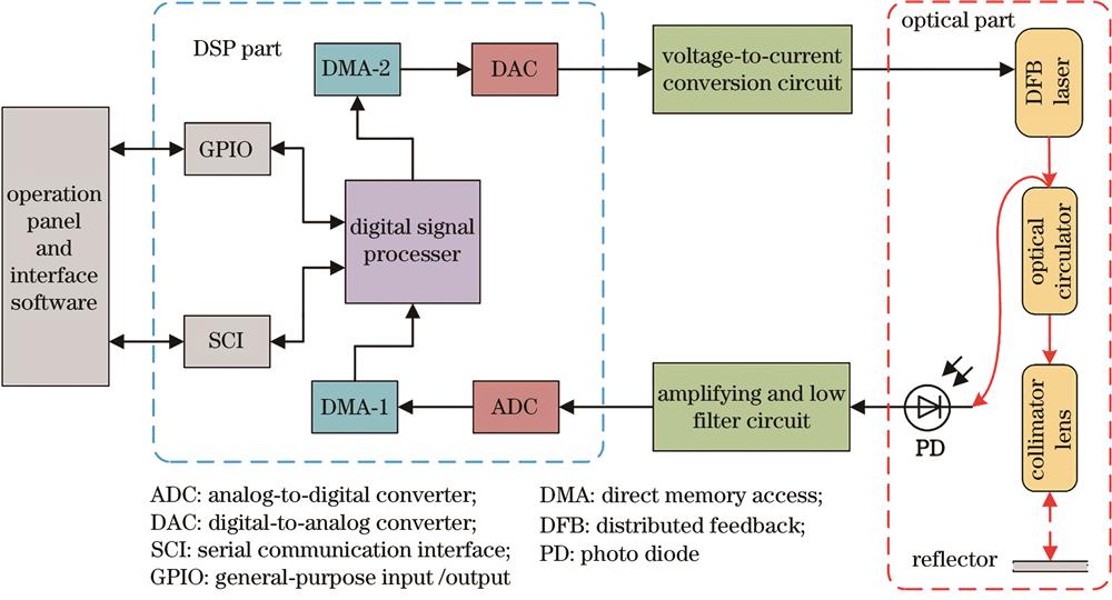
    Fig. 1. Schematic of FMCW fiber-optic displacement sensor
    Optical measurement structure of FMCW optical-fiber displacement sensor
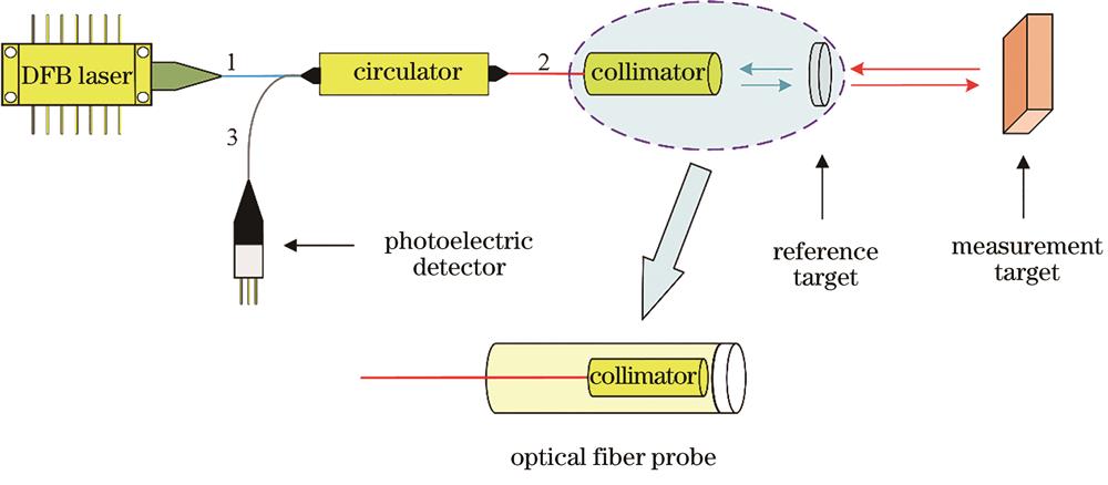
    Fig. 2. Optical measurement structure of FMCW optical-fiber displacement sensor
    Schematic of DMA transfer process. (a) Sawtooth wave modulation signal output; (b) beat frequency signal acquisition
    Fig. 3. Schematic of DMA transfer process. (a) Sawtooth wave modulation signal output; (b) beat frequency signal acquisition
    DMA interrupt calculation process
    Fig. 4. DMA interrupt calculation process
    Schematic of calculating steps of beat signal. (a) Interception of valid signal; (b) calculation of theoretical wave peaks; (c) calculation of theoretical troughs; (d) calculation of amplitude and zero bias; (e) trends in extrapolating beat signals; (f) standard beat signal at fixed point
    Fig. 5. Schematic of calculating steps of beat signal. (a) Interception of valid signal; (b) calculation of theoretical wave peaks; (c) calculation of theoretical troughs; (d) calculation of amplitude and zero bias; (e) trends in extrapolating beat signals; (f) standard beat signal at fixed point
    Phase solution results of inverse cosine look-up method. (a) Calculation of relative amplitude; (b) curve of arccosine tables
    Fig. 6. Phase solution results of inverse cosine look-up method. (a) Calculation of relative amplitude; (b) curve of arccosine tables
    Result of integral period phase accumulation. (a) Δφ>π; (b) Δφ<π
    Fig. 7. Result of integral period phase accumulation. (a) Δφ>π; (b) Δφ<π
    Experimental devices
    Fig. 8. Experimental devices
    Standard deviation and time consuming of displacement drift at different fixed points
    Fig. 9. Standard deviation and time consuming of displacement drift at different fixed points
    Standard deviation of measurement error under different displacements. (a) 200 mm; (b) 400 mm; (c) 600 mm
    Fig. 10. Standard deviation of measurement error under different displacements. (a) 200 mm; (b) 400 mm; (c) 600 mm
    Linearity and repeatability test results
    Fig. 11. Linearity and repeatability test results
    Types of phase detection algorithmAdaptation speed /(mm·s-1Algorithm time-consuming /μsMeasurement standard deviation /nm
    Extreme point detection0.38752.392.81
    Peak prediction phase detection15.5015.972.73
    Table 1. Performance comparison between peak prediction phase detection algorithm and existing algorithms
    Qiming Sheng, Gang Zheng, Xiongxing Zhang, Yuan Han, Yuan Guo, Mengdi Nie. Fast Signal Processing Method for Frequency-Modulated Continuous-Wave Interferometric Fiber-Optic Displacement Sensor[J]. Laser & Optoelectronics Progress, 2021, 58(21): 2112003
    Download Citation