
Shengyou Zhong, Libin Yao, Mingguo Fan, Zhengfen Li. 1280 × 1024, 10 μm digital IRFPA readout integrated circuit design (Invited)[J]. Infrared and Laser Engineering, 2022, 51(4): 20211113
- Infrared and Laser Engineering
- Vol. 51, Issue 4, 20211113 (2022)
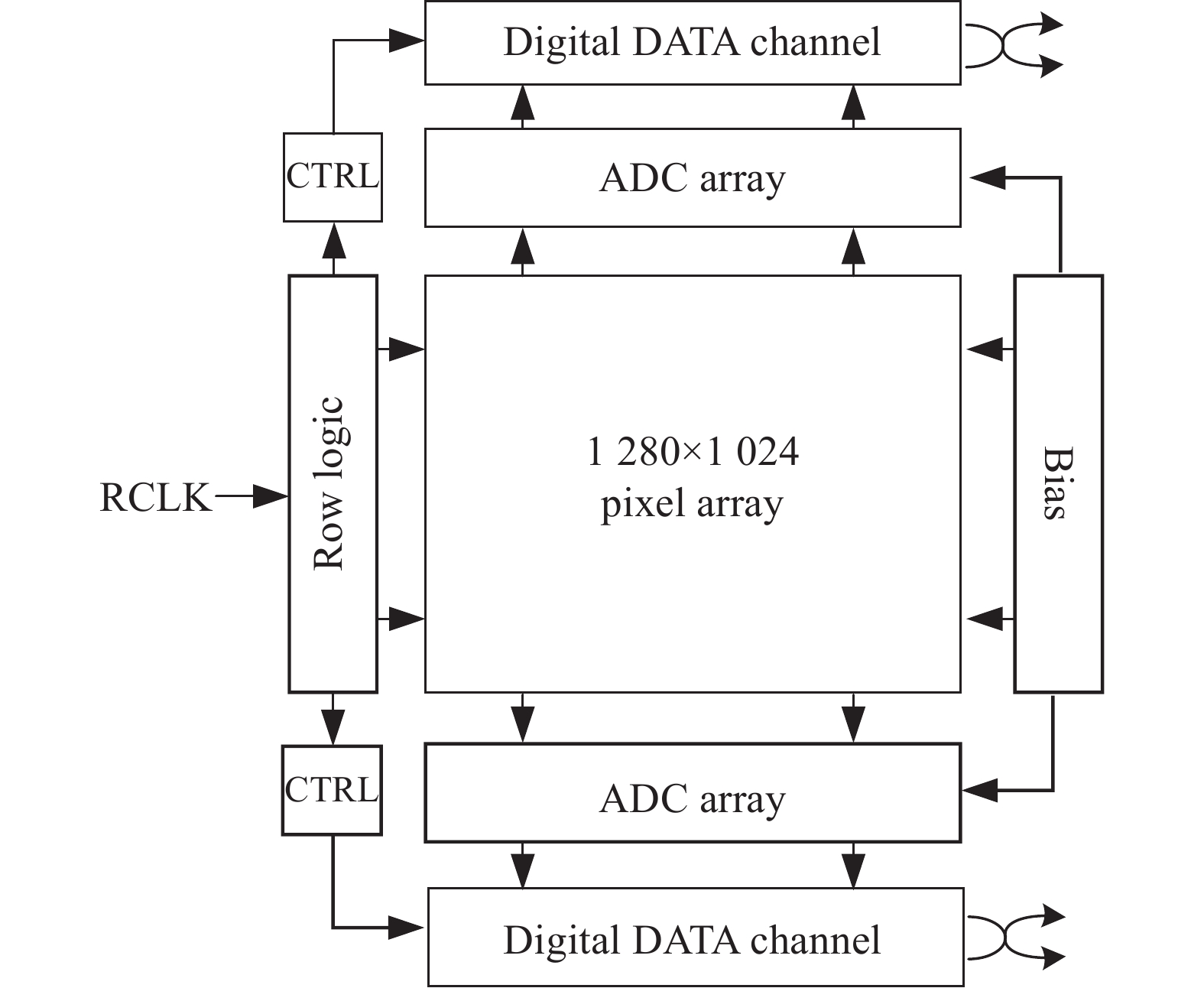
Fig. 1. Diagram of the 1280 × 1024, 10 μm DROIC
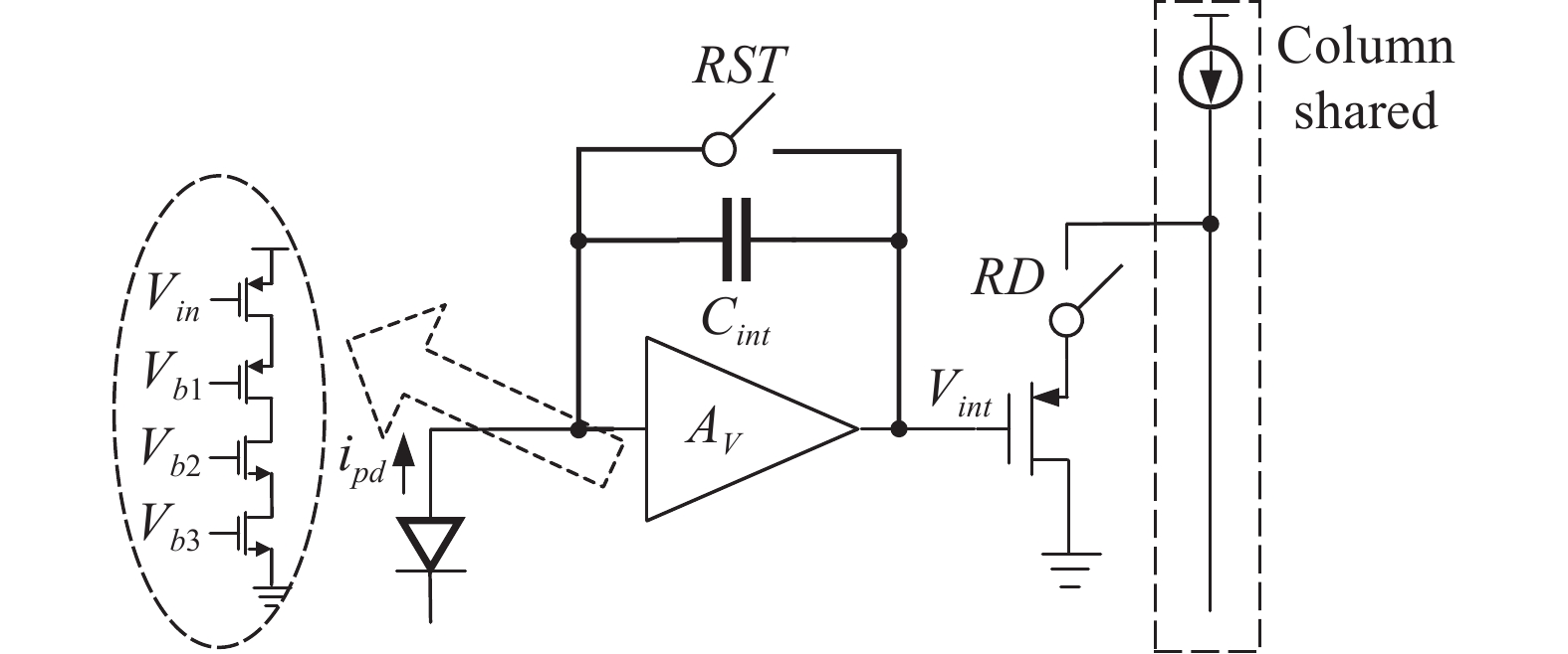
Fig. 2. Schematic of readout unit circuit
Fig. 3. Comparation of integrations between 3T and CTIA circuit
Fig. 4. Diagram of the second order Incremental Sigma-Delta modulator
Fig. 5. OTA with input stage offset cancellation circuit
Fig. 6. Floor plane of ADC array
Fig. 7. Diagram of 4-channel data transmission circuit
Fig. 8. Picture of the proposed 1280 × 1024, 10 μm DROIC
Fig. 9. Picture of the digital short-wave IRFPA
Fig. 10. Test result of the DROIC’s noise
Fig. 11. (a) Proposed 1280 × 1024, 10 μm DROIC’s column FPN test result; (b) Column FPN test result of 640 × 512, 15 μm DROIC mentioned in Ref. [6]
Fig. 12. Power consumption of the proposed DROIC’s all components
Fig. 13. Image1 captured by the 1280×1024 digital short-wave IRFPA
Fig. 14. Image2 captured by the 1280×1024 digital short-wave IRFPA
|
Table 1. Comparison of performance between different DROICs


Set citation alerts for the article
Please enter your email address

© Copyright 2018-2021 | Chinese Laser Press. All Rights Reserved 沪ICP备15018463号-20