• Laser & Optoelectronics Progress
  • Vol. 59, Issue 12, 1215007 (2022)
Xiang Dong1、2, Qiaosheng Feng1、*, Junfei Xia1, and Yaping Zhang1
Author Affiliations
  • 1School of Information Science and Technology, Yunnan Normal University, Kunming 650500, Yunnan , China
  • 2School of Computer and Information Engineering, Nantong Institute of Technology, Nantong 226004, Jiangsu , China
  • show less
    DOI: 10.3788/LOP202259.1215007 Cite this Article Set citation alerts
    Xiang Dong, Qiaosheng Feng, Junfei Xia, Yaping Zhang. Positioning Method of Positive Circular Weld with Left and Right Swing Interferences of Robot[J]. Laser & Optoelectronics Progress, 2022, 59(12): 1215007 Copy Citation Text show less
    Magnetic adsorption robot working on the top inner surface of the pipeline
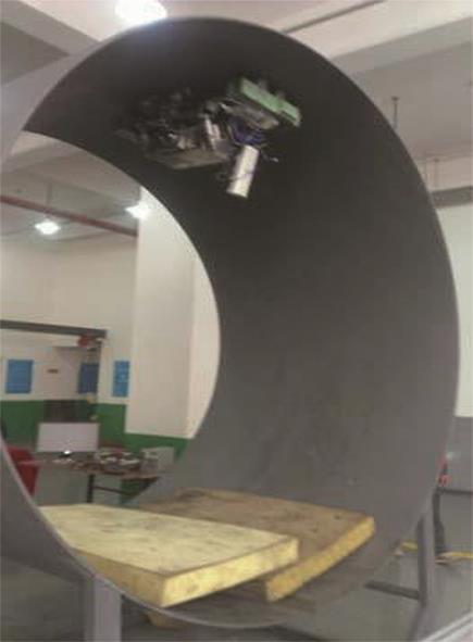
    Fig. 1. Magnetic adsorption robot working on the top inner surface of the pipeline
    Fowchart of the proposed method
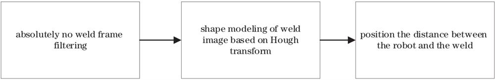
    Fig. 2. Fowchart of the proposed method
    Schematic before and after coordinate deflection
    Fig. 3. Schematic before and after coordinate deflection
    Detection of weld contour graphics. (a) Frames with weld joints; (b) Canny edge detection; (c) set of all points which satisfies the Hough transform threshold; (d) weld contour ellipse detected by MSHT; (e) frame existing weld in the composite video; (f) weld contour ellipse detected by MSHT
    Fig. 4. Detection of weld contour graphics. (a) Frames with weld joints; (b) Canny edge detection; (c) set of all points which satisfies the Hough transform threshold; (d) weld contour ellipse detected by MSHT; (e) frame existing weld in the composite video; (f) weld contour ellipse detected by MSHT
    ORB features are involved in magazine matching from different perspectives[14]. (a) ORB features matching from different perspectives; (b) (c) circular regios in Fig.5 (a)
    Fig. 5. ORB features are involved in magazine matching from different perspectives[14]. (a) ORB features matching from different perspectives; (b) (c) circular regios in Fig.5 (a)
    Images of inner surface of pipeline. (a) Frame without welds;(b)frame with circular welds
    Fig. 6. Images of inner surface of pipeline. (a) Frame without welds;(b)frame with circular welds
    Results of ORB-SLAM3 running on EuRoC MAV dataset. (a) ORB feature extraction rendering diagram running on EuRoC MAV dataset scenario; (b) field scene point cloud map and camera motion track
    Fig. 7. Results of ORB-SLAM3 running on EuRoC MAV dataset. (a) ORB feature extraction rendering diagram running on EuRoC MAV dataset scenario; (b) field scene point cloud map and camera motion track
    Results of feature extraction and map construction in the pipeline by ORB-SLAM3. (a) Extraction of ORB feature points in scenes containing welds; (b) point cloud map and camera motion track constructed during running to scene Fig.8 (a)
    Fig. 8. Results of feature extraction and map construction in the pipeline by ORB-SLAM3. (a) Extraction of ORB feature points in scenes containing welds; (b) point cloud map and camera motion track constructed during running to scene Fig.8 (a)
    Results of LSD-SLAM running on the LSD_ROOM.bag dataset. (a) scene contained in LSD_ROOM.bag dataset; (b) point cloud map based on Fig.9 (a)
    Fig. 9. Results of LSD-SLAM running on the LSD_ROOM.bag dataset. (a) scene contained in LSD_ROOM.bag dataset; (b) point cloud map based on Fig.9 (a)
    Results of LSD-SLAM running in pipeline inspection environment. (a) Result of shooting which robot moves forward in the scene without welds; (b) point cloud map which the moving robot constructed in the scene Fig.10 (a); (c) result of shooting which robot moves forward in the scene with welds; (d) point cloud map which the moving robot constructed in the scene Fig.10 (c)
    Fig. 10. Results of LSD-SLAM running in pipeline inspection environment. (a) Result of shooting which robot moves forward in the scene without welds; (b) point cloud map which the moving robot constructed in the scene Fig.10 (a); (c) result of shooting which robot moves forward in the scene with welds; (d) point cloud map which the moving robot constructed in the scene Fig.10 (c)
    FrameabijDetection distanceTruth distanceAngle /(°)
    1120.68120.83242.33239.42
    2122.35122.55242.37239.44
    3124.31124.21242.45239.46
    4126.21126.04242.46239.46272.03272.069.97
    5127.84128.10242.46239.43268.78268.1210.10
    6130.02129.34242.50239.45264.23264.1810.04
    7131.44132.22242.59239.44260.88260.249.92
    8133.29133.69242.62239.45255.62256.3110.18
    Table 1. Detection results of distance and swing angle when there is left and right swing
    Xiang Dong, Qiaosheng Feng, Junfei Xia, Yaping Zhang. Positioning Method of Positive Circular Weld with Left and Right Swing Interferences of Robot[J]. Laser & Optoelectronics Progress, 2022, 59(12): 1215007
    Download Citation