
Jie Liu, Tingzhu Bai, Xueju Shen, Shuaifeng Dou, Chao Lin, Qi Chen. Robustness Analysis and Optimization of Parallel Encryption System for Multi-Channel Images in an Optical Joint Transform Correlator Architecture[J]. Acta Optica Sinica, 2017, 37(12): 1210001
- Acta Optica Sinica
- Vol. 37, Issue 12, 1210001 (2017)
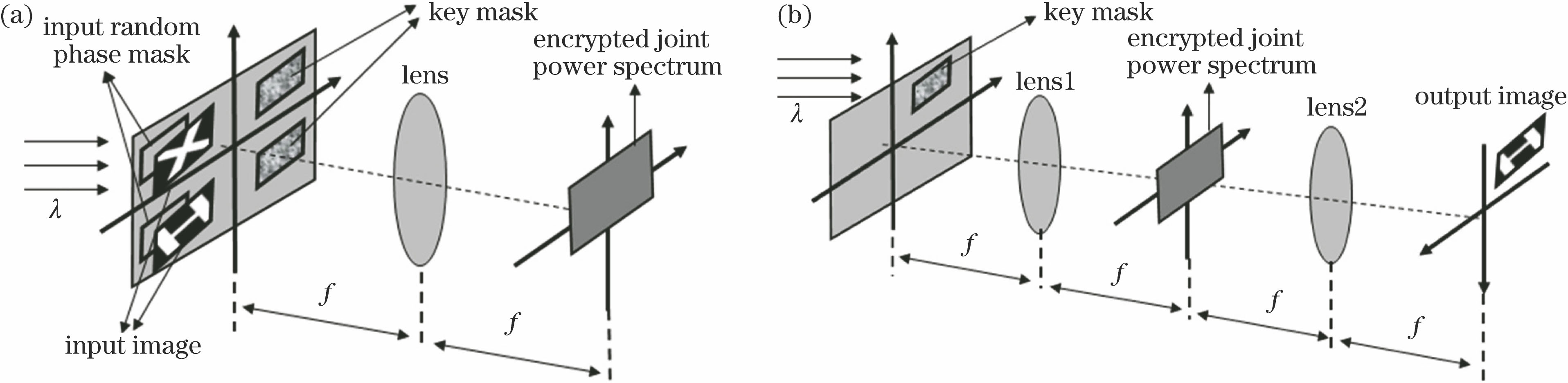
Fig. 1. Schematic of parallel encryption for multi-channel images based on JTC. (a) Encryption step; (b) decryption step
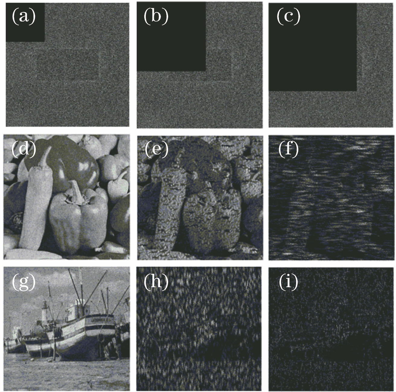
Fig. 2. Decryption results based on ciphertext after side occlusion. (a) Ciphertext after 10% occlusion; (b) ciphertext after 30% occlusion; (c) ciphertext after 50% occlusion; (d) XCC=0.98(10% occlusion); (e) XCC=0.81(30% occlusion); (f) XCC=0.42(50% occlusion); (g) XCC=0.98(10% occlusion); (h) XCC=0.4(30% occlusion); (i) XCC=0.21(50% occlusion)
Fig. 3. Decryption results based on ciphertext after center occlusion. (a) Ciphertext after 10% occlusion; (b) ciphertext after 30% occlusion; (c) ciphertext after 50% occlusion; (d) XCC=0.47(10% occlusion); (e) XCC=0.25(30% occlusion); (f) XCC=0.25(50% occlusion); (g) XCC=0.43(10% occlusion); (h) XCC=0.21(30% occlusion); (i) XCC=0.21(50% occlusion)
Fig. 4. Decryption results based on ciphertext after noise attack when the mean value is 0. (a) Ciphertext (ERMS=0.1); (b) ciphertext (ERMS=0.3); (c) ciphertext (ERMS=0.5); (d) XCC=0.97 (ERMS=0.1); (e) XCC=0.82 (ERMS=0.3); (f) XCC=0.62 (ERMS=0.5); (g) XCC=0.96 (ERMS=0.1); (h) XCC=0.77 (ERMS=0.3); (i) XCC=0.54 (ERMS=0.5)
Fig. 5. Optimal strategy for JPS arrangement. (a) Splice in horizontal direction for dual channels; (b) splice in vertical direction for dual channels; (c) splice in horizontal direction for three channels; (d) two-dimensional splice for four channels
Fig. 6. Decryption results of optimized encryption system. (a) Optimized JPS; (b) decryption result of pepper with a single key; (c) decryption result of boat with a single key
Fig. 7. Decryption results based on optimized ciphertext after side occlusion. (a) Ciphertext after 10% occlusion; (b) ciphertext after 30% occlusion; (c) ciphertext after 50% occlusion; (d) XCC=0.94 (10% occlusion); (e) XCC=0.73 (30% occlusion); (f) XCC=0.68 (50% occlusion); (g) XCC=0.77 (10% occlusion); (h) XCC=0.63 (30% occlusion); (i) XCC=0.52 (50% occlusion); (j) curves between the CC value and the occlusion ratio of JPS before and after optimization
Fig. 8. Decryption results based on optimized ciphertext after center occlusion. (a) Ciphertext after 10% occlusion; (b) ciphertext after 30% occlusion; (c) ciphertext after 50% occlusion; (d) XCC=0.85 (10% occlusion); (e) XCC=0.69 (30% occlusion); (f) XCC=0.59 (50% occlusion); (g) XCC=0.78 (10% occlusion); (h) XCC=0.63 (30% occlusion); (i) XCC=0.53 (50% occlusion); (j) curves between the CC value and the occlusion ratio of JPS before and after optimization
Fig. 9. Schematic of experimental system
Fig. 10. Composition of experimental system
Fig. 11. Decryption results of letters. (a) Input plane; (b) optimized JPS; (c) simultaneous decryption of two letters; (d) decryption of letter B; (e) decryption of letter C
Fig. 12. Decryption results with side occlusion. (a) Without occlusion; (b) 10% side occlusion; (c) 30% side occlusion; (d) 50% side occlusion
Fig. 13. Decryption results with center occlusion. (a) Without occlusion; (b) 10% center occlusion; (c) 30% center occlusion; (d) 50% center occlusion
Fig. 14. Decryption results with noise attack under different conditions. (a) ERMS=0; (b) ERMS=0.1; (c) ERMS=0.3; (d) ERMS=0.5

Set citation alerts for the article
Please enter your email address
© Copyright 2018-2021 | Chinese Laser Press. All Rights Reserved 沪ICP备15018463号-20