• Advanced Photonics
  • Vol. 1, Issue 2, 024001 (2019)
Weiqiang Ding1、*, Tongtong Zhu1、2, Lei-Ming Zhou2, and Cheng-Wei Qiu2、*
Author Affiliations
  • 1Harbin Institute of Technology, Department of Physics, Harbin, China
  • 2National University of Singapore, Department of Electrical and Computer Engineering, Singapore
  • show less
    DOI: 10.1117/1.AP.1.2.024001 Cite this Article Set citation alerts
    Weiqiang Ding, Tongtong Zhu, Lei-Ming Zhou, Cheng-Wei Qiu. Photonic tractor beams: a review[J]. Advanced Photonics, 2019, 1(2): 024001 Copy Citation Text show less
    (a) Definition of the OPF used in this paper. The source and object are centered at A and B, respectively, and the center-to-center vector AB (dashed blue) defines the pulling or pushing force axis. When the angle θ between the optical force F (the black thick arrow) and the axis AB is larger than π/2, the force is a pulling one. The special case of θ=π is the most desirable in practice. When θ is less than π/2, the force is a pushing one and the special case of θ=0 is widely investigated in practice. (b)–(e) Four different mechanisms for achieving the OPF, where the special case of θ=π is shown for clarity and S shows the energy flow. OPF (b) using structured light beams, (c) using objects with exotic optical parameters, (d) using structured background media, and (e) using the photophoresis effect.
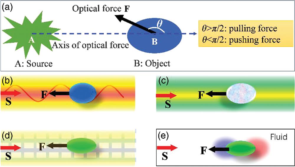
    Fig. 1. (a) Definition of the OPF used in this paper. The source and object are centered at A and B, respectively, and the center-to-center vector AB (dashed blue) defines the pulling or pushing force axis. When the angle θ between the optical force F (the black thick arrow) and the axis AB is larger than π/2, the force is a pulling one. The special case of θ=π is the most desirable in practice. When θ is less than π/2, the force is a pushing one and the special case of θ=0 is widely investigated in practice. (b)–(e) Four different mechanisms for achieving the OPF, where the special case of θ=π is shown for clarity and S shows the energy flow. OPF (b) using structured light beams, (c) using objects with exotic optical parameters, (d) using structured background media, and (e) using the photophoresis effect.
    OPF by structured light beams: (a) experimental demonstration of OPF by a solenoid beam:24" target="_self" style="display: inline;">24 (a1) the spiral intensity peak pattern in experiment, (a2) wave vector back down the spiral, and (a3) experimental measurement of the pushing and pulling trace. (b) Theoretical proposal of OPF achieved by the excitation of multipoles in the object,27" target="_self" style="display: inline;">27,40" target="_self" style="display: inline;">40 and (c1) theoretical proposal of OPF by a Bessel beam with a cone angle of α. (c2) and (c3) OPF changes with the relative permittivity and permeability of the object.28" target="_self" style="display: inline;">28
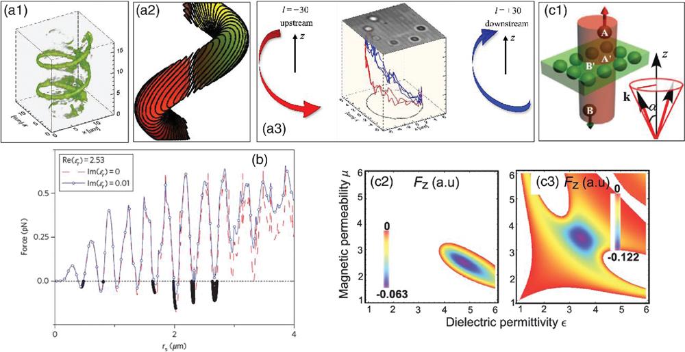
    Fig. 2. OPF by structured light beams: (a) experimental demonstration of OPF by a solenoid beam:24 (a1) the spiral intensity peak pattern in experiment, (a2) wave vector back down the spiral, and (a3) experimental measurement of the pushing and pulling trace. (b) Theoretical proposal of OPF achieved by the excitation of multipoles in the object,27,40 and (c1) theoretical proposal of OPF by a Bessel beam with a cone angle of α. (c2) and (c3) OPF changes with the relative permittivity and permeability of the object.28
    OPF by the interference of multiple beams. (a) Using the interference of a series of plane waves,55" target="_self" style="display: inline;">55 and (b) using the interference of two Gaussian beams:54" target="_self" style="display: inline;">54 (b1) schematic illustration of the configuration, (b2) the s-polarization can get forward scattering enhancement, and thus a pulling force, and (b3) the p-polarization cannot. (c) OPF using the interference of two codirectional Bessel beams:56" target="_self" style="display: inline;">56 (c1) schematic illustration of the Bessel beam by an SLM and a lens, (c2) volumetric reconstruction of the Bessel beam, (c3) phase hologram encoding the optical conveyor, and (c4) volumetric reconstruction of the beam projected by the hologram in (c3).
    Fig. 3. OPF by the interference of multiple beams. (a) Using the interference of a series of plane waves,55 and (b) using the interference of two Gaussian beams:54 (b1) schematic illustration of the configuration, (b2) the s-polarization can get forward scattering enhancement, and thus a pulling force, and (b3) the p-polarization cannot. (c) OPF using the interference of two codirectional Bessel beams:56 (c1) schematic illustration of the Bessel beam by an SLM and a lens, (c2) volumetric reconstruction of the Bessel beam, (c3) phase hologram encoding the optical conveyor, and (c4) volumetric reconstruction of the beam projected by the hologram in (c3).
    Theoretical proposals of OPF by objects with exotic optical parameters: (a) OPF on an object with optical gain,25" target="_self" style="display: inline;">25 (b) OPF on an extremely anisotropic lossy object,66" target="_self" style="display: inline;">66 and (c) OPF on a PT-bilayer object with loss and gain.67" target="_self" style="display: inline;">67
    Fig. 4. Theoretical proposals of OPF by objects with exotic optical parameters: (a) OPF on an object with optical gain,25 (b) OPF on an extremely anisotropic lossy object,66 and (c) OPF on a PT-bilayer object with loss and gain.67
    OPF related to chirality. (a) OPF on a chiral structure formed by metallic spheres aligned on a spiral line (black curve):69" target="_self" style="display: inline;">69 (a1) the schematic structure and (a2) optical force versus the diameter of the spheres. (b) OPF on a chiral slab with the assistance of reflection mirror:70" target="_self" style="display: inline;">70 (b1) the chiral slab is transparent for the incident handedness of light, but absorptive for the reflection beams; due to the way handedness is reversed by the mirror, the total force is pulling; (b2) when incident handedness is reversed, the slab is pushing forward.
    Fig. 5. OPF related to chirality. (a) OPF on a chiral structure formed by metallic spheres aligned on a spiral line (black curve):69 (a1) the schematic structure and (a2) optical force versus the diameter of the spheres. (b) OPF on a chiral slab with the assistance of reflection mirror:70 (b1) the chiral slab is transparent for the incident handedness of light, but absorptive for the reflection beams; due to the way handedness is reversed by the mirror, the total force is pulling; (b2) when incident handedness is reversed, the slab is pushing forward.
    OPF realized on an interface. (a) Optical pulling on an air–water interface, which is realized by the linear momentum increase when the incident light is scattered from air to water through the object.38" target="_self" style="display: inline;">38 (b) Optical pulling on a plasmonic surface, which is realized by the directional excitation of the SPP on the air–silver interface.75" target="_self" style="display: inline;">75
    Fig. 6. OPF realized on an interface. (a) Optical pulling on an air–water interface, which is realized by the linear momentum increase when the incident light is scattered from air to water through the object.38 (b) Optical pulling on a plasmonic surface, which is realized by the directional excitation of the SPP on the air–silver interface.75
    OPF realized in waveguide channels: (a) optical resonant pulling of a ring resonator by a dual-mode optical waveguide,79" target="_self" style="display: inline;">79 (b) OPF in a hollow core photonic crystal waveguide,80" target="_self" style="display: inline;">80 and (c) tunable optical pushing and pulling using a waveguide made of phase change material of Ge2Sb2Te5 (GST).81" target="_self" style="display: inline;">81
    Fig. 7. OPF realized in waveguide channels: (a) optical resonant pulling of a ring resonator by a dual-mode optical waveguide,79 (b) OPF in a hollow core photonic crystal waveguide,80 and (c) tunable optical pushing and pulling using a waveguide made of phase change material of Ge2Sb2Te5 (GST).81
    OPF in waveguide channels with effective negative mode index: (a) a square dielectric waveguide array, which mimics the Clarricoats-Waldron waveguide with negative mode index;88" target="_self" style="display: inline;">88 (b1) and (b2) a plasmonic film in vacuum, which supports backward wave and can resonantly pull a dielectric sphere above it with very high-momentum-to-force efficiency;89" target="_self" style="display: inline;">89 and (c) optical pulling in a biaxial slab layered structure.90" target="_self" style="display: inline;">90
    Fig. 8. OPF in waveguide channels with effective negative mode index: (a) a square dielectric waveguide array, which mimics the Clarricoats-Waldron waveguide with negative mode index;88 (b1) and (b2) a plasmonic film in vacuum, which supports backward wave and can resonantly pull a dielectric sphere above it with very high-momentum-to-force efficiency;89 and (c) optical pulling in a biaxial slab layered structure.90
    OPF in a PC structure by the SC mode.96" target="_self" style="display: inline;">96 (a) Scattering of the SC mode by an embedded object. (b) Intensity profile along the beam symmetry axis; a negative intensity gradient across the object can be observed clearly, which is the physical origin for the OPF. (c) and (d) Intensity profile of the beam around the object at two different positions.
    Fig. 9. OPF in a PC structure by the SC mode.96 (a) Scattering of the SC mode by an embedded object. (b) Intensity profile along the beam symmetry axis; a negative intensity gradient across the object can be observed clearly, which is the physical origin for the OPF. (c) and (d) Intensity profile of the beam around the object at two different positions.
    Experimental demonstrations of OPF assisted by photophoretic force. (a) Stable pulling and pushing of a coated empty glass sphere using vector beams with a doughnut intensity pattern.107" target="_self" style="display: inline;">107 For azimuthally polarized beam, the force is pulling, while for radially polarized beam, the force is pushing. (b) Pulling and pushing of a metallic plate on a fiber taper.108" target="_self" style="display: inline;">108
    Fig. 10. Experimental demonstrations of OPF assisted by photophoretic force. (a) Stable pulling and pushing of a coated empty glass sphere using vector beams with a doughnut intensity pattern.107 For azimuthally polarized beam, the force is pulling, while for radially polarized beam, the force is pushing. (b) Pulling and pushing of a metallic plate on a fiber taper.108
    Weiqiang Ding, Tongtong Zhu, Lei-Ming Zhou, Cheng-Wei Qiu. Photonic tractor beams: a review[J]. Advanced Photonics, 2019, 1(2): 024001
    Download Citation