Abstract
Usually, an unfocused light beam, such as a paraxial Gaussian beam, can exert a force on an object along the direction of light propagation, which is known as light pressure. Recently, however, it was found that an unfocused light beam can also exert an optical pulling force (OPF) on an object toward the source direction; the beam is accordingly named an optical tractor beam. In recent years, this intriguing force has attracted much attention and a huge amount of progress has been made both in theory and experiment. We briefly review recent progress achieved on this topic. We classify the mechanisms to achieve an OPF into four different kinds according to the dominant factors. The first one is tailoring the incident beam. The second one is engineering the object’s optical parameters. The third one is designing the structured material background, in which the light–matter interaction occurs, and the fourth one is utilizing the indirect photophoretic force, which is related to the thermal effect of light absorption. For all the methods, we analyze the basic principles and review the recent achievements. Finally, we also give a brief conclusion and an outlook on the future development of this field.1 Introduction
Since the pioneering works by Ashkin,1–3 optical manipulation utilizing the mechanical effect of light has developed extensively in various contexts. Optical tweezers and other related manipulation technologies have become indispensable in various disciplines, including biology,4–7 chemistry,8 quantum science and technology,9–11 and nanotechnology.12–14 One remarkable trend amid this progress is that optical manipulation has been extended, from the initial single freedom of trapping using the conservative optical force, to multiple freedoms using both conservative and nonconservative forces,15 including pushing,16 pulling,17 lateral shifting, rotating,18–21 and spinning.22
Among all the newly developed manipulation freedoms, optical pulling is one of the most interesting and has attracted much attention,23–26 due to the potential applications and intriguing physics behind it. Usually, when illuminated by a tightly focused beam, the intensity gradient resorting force can overcome the scattering force, and the object can be trapped near the focus spot.2 On the other hand, when illuminated by an unfocused beam, the intensity gradient force vanishes and the object is expected to be pushed away.1 However, about 10 years ago, researchers found that the object may experience an optical pulling force (OPF) toward the source direction when illuminated by an unfocused beam, such as a diffraction-free (nondiffraction) Bessel beam,27,28 which is named an optical tractor beam (OTB). Although it seems counterintuitive, OPF has been theoretically proved and experimentally demonstrated within recent years, as will be reviewed in this paper.
The pulling force by a single beam was first noticed by Marston in acoustics,29,30 who found that the axial radiation force of a Bessel acoustic beam on a sphere could be inverted (from pushing to pulling) for some carefully designed objects, which suppressed the scattering to the back hemisphere. Since the acoustic and optical waves share many common features, it is not surprising to find pulling force in optics using similar methods. Shortly after Marston, optical pulling phenomena were predicted by Lee et al.24 in an optical solenoid beam, which is a diffractionless beam with in-plane intensity peak spirals around the optical axis. In the same year, the concept of OTB was confirmed by Sukhov and Dogariu.26 Following, another two theoretical works published independently by Chen et al.27 and Novitsky et al.28 gave a clear analysis of the criteria and method to obtain an OPF. Since then, the OTB began to attract more and more attention due to the interesting phenomena and physics involved and possible applications in optical manipulation technology. What is more, the concept of OTB and pulling force has been extended to other forms of wave, including the water wave31 and quantum matter wave,32 which are beyond the scope of this paper.
Sign up for Advanced Photonics TOC. Get the latest issue of Advanced Photonics delivered right to you!Sign up now
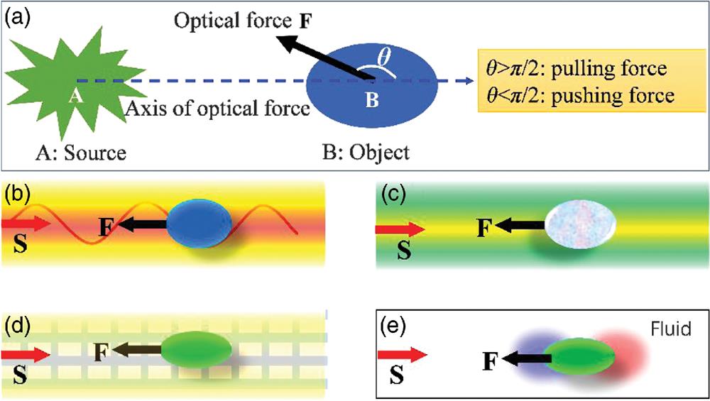
Here we would like to make a clear and consistent definition of the OPF. Usually, pulling means that the object moves against (or the force is reverse to) the direction of light propagation. However, the “direction of light propagation” is ambiguous in some cases since the directions of wavevector and Poynting vector may be different, especially in structured optical beams and nanostructures related to OPF. Due to this reason, in this paper, OPF is defined relative to the relative position of the optical source and object, as shown in Fig. 1(a). Suppose the source is located at A and the object is at B, then the center-to-center vector (the blue dashed arrow) defines the axis of the force. The pulling force means that the angle between the optical force (the thick red arrow) and the axis is larger than , as shown in Fig. 1(a). In this case, the projection of optical force on is directed from B to A. On the contrary, the pushing force means that the force projection is from A to B, or . Since the relative position of the source and object can be determined explicitly, this definition is reasonable and acceptable.

Figure 1.(a) Definition of the OPF used in this paper. The source and object are centered at A and B, respectively, and the center-to-center vector (dashed blue) defines the pulling or pushing force axis. When the angle between the optical force (the black thick arrow) and the axis is larger than , the force is a pulling one. The special case of is the most desirable in practice. When is less than , the force is a pushing one and the special case of is widely investigated in practice. (b)–(e) Four different mechanisms for achieving the OPF, where the special case of is shown for clarity and shows the energy flow. OPF (b) using structured light beams, (c) using objects with exotic optical parameters, (d) using structured background media, and (e) using the photophoresis effect.
In this work, we aim to make a brief review on the progressing topic of OPF. From the viewpoint of linear momentum conservation, in order to get an OPF, the effective forward momentum of the incident light should be enhanced when scattered by the object. Due to this reason, many works in this topic are about tailoring the momentums of light beams when they impinge on and are scattered by the object using various mechanics. In order to make this review clear and easy to follow, we classify the mechanisms of OPF into four kinds based on the predominant factor in the pulling process, as shown in Figs. 1(b)–1(d). The first one is using structured beams, the second is using objects with exotic structures and parameters, the third one is using a structured background that supports special modes, and the last one is using the photophoretic force that results from light absorption. Certainly, this classification method is not rigorous and not unique, because in some cases more than one effect is involved simultaneously.
Before discussing OPF, we would like to address the theoretical and numerical methods used to investigate the OPF. Basically, the calculation methods of OPF are exactly the same as those used in optical trapping.15 For objects much smaller than the wavelength of the trapping light, dipole approximation could be used to obtain analytical formulas for the optical forces,33 from which the OPF can be identified. In this case, the outstanding angular scattering features of magnetic or larger dielectric particles determine the direction of the optical force, and the Kerker scattering conditions are useful in exploring the OPF.34–36 For objects much larger than the wavelength, the ray tracing method could be used to calculate the optical forces.37,38 For the objects with moderate size comparable to the wavelength, an integration of Maxwell’s stress tensor on a closed surface surrounding the object is necessary to calculate the optical force,39 and some numerical simulation methods, such as the finite-difference time-domain method or finite-element methods, are typically used to obtain the electromagnetic fields around the object. Since those methods can be found easily in the literature, we will skip these detailed methods, and readers may refer to the references when necessary.
2 Optical Pulling Force Achieved by Structured Beams
Using a structured light beam beyond the plane wave and the paraxial Gaussian beam is the first method proposed for achieving OPF.24 There are several different specific configurations in this mechanism. The first one is using a single-structured diffraction-free beam, such as the Bessel beam and solenoid beam. The second one is using the interferences of two or more structured waves, such as two Bessel beams, two Gaussian beams, or multiple plane waves.
2.1 Optical Pulling by a Single-Structured Beam
Lee et al.24 found a diffraction-free solution for the Helmholtz equation, i.e., the optical solenoid beam, in which the principal intensity peak spirals around the optical axis and its wavefront are characterized by an independent helical pitch, as shown in Fig. 2(a1). In this beam, the intensity gradient force traps a small object to the maximum intensity, whereas the scattering force can drive the object around the spiral, which is determined by the phase gradient force.41 When the wavefront’s pitch relative to propagation direction is tuned from forward to retrograde, OPF will be obtained. Finally, the combination of those two forces pulls the object to the source direction, as indicated by the experimental demonstration depicted in Fig. 2(a3). Another similar helical tractor beam was also reported by Carretero et al.42
Figure 2.OPF by structured light beams: (a) experimental demonstration of OPF by a solenoid beam:24 (a1) the spiral intensity peak pattern in experiment, (a2) wave vector back down the spiral, and (a3) experimental measurement of the pushing and pulling trace. (b) Theoretical proposal of OPF achieved by the excitation of multipoles in the object,27,40 and (c1) theoretical proposal of OPF by a Bessel beam with a cone angle of . (c2) and (c3) OPF changes with the relative permittivity and permeability of the object.28
Another kind of structured beam for generating an OPF is the Bessel beam,27,28,43 which is also diffraction-free within a limited region in propagation. Different from the solenoid beam, the intensity peak in this beam is along a straight line, which can be obtained using an axicon44 or an optical metasurface.45,46 When a properly designed particle is illuminated by such a beam, multipoles (not only the dipole) may be excited simultaneously, and the interferences between them can maximize the forward scattering while suppressing the backward scattering.27,40 Finally, the net linear momentum propagation along the direction of propagation is increased, and in turn the object is recoiled toward the light source, as shown in Fig. 2(b). For some values of particle size, the pulling is stable for a transparent and lossy object, marked by the thick black curve in Fig. 2(b).
The pulling force can also be understood from the direction of the wavevector of Bessel beams.28 A Bessel beam can be regarded as the superposition of a series of plane waves, in which the wavevectors lie on a cone with an apex angle relative to the propagation direction (such as the axis), as shown in Fig. 2(c1). When scattered by a carefully designed object, the wavevector may be realigned forcedly to the direction due to the scattering of the object. Since the amplitude of is related to the linear momentum of photons, the momentum projection along the direction is enhanced, and the extra momentums are balanced by the backward force on the object, as shown in Figs. 2(c2) and 2(c3). What is more, the transverse stability is also guaranteed in this configuration, due to the restoring intensity gradient force provided by the Bessel beam.
One disadvantage of using a Bessel beam to generate OPF is the sensitivity to the object size and optical parameters of the object, perturbation of which may disturb or even destroy the optical traction completely. (Certainly, this feature is also quite useful, such as in particle sorting, since the pulling force is size and optical parameters dependent.27,28) In order to overcome this shortcoming, Novitsky et al.43 proposed universal criteria for the material-independent or size-independent OTB and found that the nonparaxial Bessel beam is an excellent candidate for this kind of robust tractor beam. Pfeiffer and Grbic47 reported an interesting method to realize the needed Bessel beam using a practical metasurface. The designed silicon metasurface can convert the linearly polarized Gaussian beam into the superposition of transverse-electric and transverse-magnetic polarized Bessel beams, which can stably pull a polystyrene sphere within the diffraction-free range. Recently, the core–shell structure was proved to have potential power in the tailoring of light scattering,48,49 and thus it is also used in the generation of enhanced OPF, even in the Rayleigh region using Bessel beams, which is also transversely stable.50 Also a cylindrical shape of dielectric particles can effectively mitigate the nonparaxiality requirements to the Bessel beam.51 A more comprehensive analysis of stable pulling by a Bessel beam is provided in Ref. 52. Interestingly, except for cylindrical objects, other kinds of elongated objects, such as optically bound particles, can also be used to enhance the OPF.53,54
2.2 Optical Pulling by Interferences of Multiple Beams
Although a single-structured beam can act as a tractor beam, multiple beams cooperating together can make the OPF more flexible. In the supplementary materials of Ref. 27, Chen et al. theoretically proposed that two plane waves are possible to pull some small object. Later, Sukhov and Dogariu55 theoretically proposed the general mechanism to realize optical pulling for arbitrary objects using multiple plane waves. The method is to launch a series of plane waves (such as 24 waves) propagating along a cone surface (with the apex angle of ) with the same amplitude but optimized relative polarizations and phases, as shown in Fig. 3(a). In this scheme, all the plane wave components have the same longitudinal wavevector, thus form a diffraction-free beam suitable for long-range pulling. For the optimized incident waves, a pulling force of is obtained. Actually, this latter method based on multiple-plane wave interfaces is more powerful and could be optimized to get an almost arbitrary scattering pattern and various kinds of optical forces, such as the transverse optical force.
Figure 3.OPF by the interference of multiple beams. (a) Using the interference of a series of plane waves,55 and (b) using the interference of two Gaussian beams:54 (b1) schematic illustration of the configuration, (b2) the s-polarization can get forward scattering enhancement, and thus a pulling force, and (b3) the p-polarization cannot. (c) OPF using the interference of two codirectional Bessel beams:56 (c1) schematic illustration of the Bessel beam by an SLM and a lens, (c2) volumetric reconstruction of the Bessel beam, (c3) phase hologram encoding the optical conveyor, and (c4) volumetric reconstruction of the beam projected by the hologram in (c3).
While the multiple-plane wave interference method is powerful, handling so many waves is not easy in practice. Is it possible to get an OPF using fewer waves? Brzobohatý et al.54 theoretically proposed and experimentally demonstrated the OPF on a polystyrene particle with a radius of 410 nm using two Gaussian beams, or using one Gaussian beam and a reflection mirror, as shown in Fig. 3(b). The key point in this geometry is the large angle between the two incident waves (the angle between wavevector and ranges from 152 deg to 180 deg), which makes the majority of the beam scatter in a forward direction for s-polarization. When the transverse forces are cancelled with each other, a final net force is left reverse to the direction of , i.e., an OPF. For the p-polarization, however, the force is always pushing. Since the direction of the force is size-dependent and polarization-dependent, this method is also efficient in particle sorting and can be switched by polarization.
Another mechanism for OPF achieved by Ruffner et al.54 seems more flexible, as shown in Fig. 3(c). The directions of the particle could be tuned actively and it behaves as an optical conveyor.57,58 They launched two coherent Bessel beams along the same direction with slightly different longitudinal wavevectors and tunable relative phases, and an active tractor beam was obtained. Since the wavevectors of the two beams are different, a series of intensity peaks are obtained, and thus a particle could be trapped by the intensity gradient force. Then by tuning the relative phases of the two beams, the positions of the peaks could shift forward or backward, and the trapped object can be transported upstream or downstream. Actually, this principle has been investigated by Čižmár59 for submicron particle organization and bidirectional shift. Basically, this method is a little different from those mentioned above, because the scattering is not the key issue in this case, but the shift of the trapping center.57,60
3 Optical Pulling Force Achieved by Exotic Object Parameters
3.1 Optical Pulling Force by Optical Gain and Loss
Except for using one or more structured light beams, OPF is also possible to achieve using an object with proper optical features. The first one that comes to mind is the optical gain object.25,61–65 For example, Mizrahi and Fainman25 reported the idea of negative radiation pressure using gain media, such as slabs, spheres, and deep subwavelength structures, as shown in Fig. 4(a). The underlying physics is not difficult to understand. Since the object is with optical gain, the incident photon number (the total light momentum) may be amplified by the gain object when stimulated emission occurs. According to the principle of linear momentum conservation, the object will get a pulling force.
Figure 4.Theoretical proposals of OPF by objects with exotic optical parameters: (a) OPF on an object with optical gain,25 (b) OPF on an extremely anisotropic lossy object,66 and (c) OPF on a PT-bilayer object with loss and gain.67
According to the analysis above, it can be understood easily that a lossy object is not likely to be pulled. However, Novitsky and Qiu66 found that the pulling force is still possible in case of lossy object, as shown in Fig. 4(b). Using a metal-dielectric multilayer, a hyperbolic object with loss is fabricated. When illuminating a dipole sphere made of the hyperbolic material using a nonparaxial beam, OPF can be obtained when the loss is relatively small. More interestingly, Alaee et al.67 recently reported the optical pulling on a parity-time-symmetric bilayer, which is the combination of gain and loss. The pushing or pulling is dependent on the direction of the light incident on this structure. Moreover, light can exert asymmetric pulling, pushing, or zero forces on parity-time-symmetric metasurfaces, which are composed of arrays of meta-atoms (coupled spheres), by balanced loss and gain constituents.68
3.2 Optical Pulling Force Related to Chirality
Another theoretical proposal to get an OPF is using the interaction of a chiral object with chiral light.61,69–72 Comparing with the achiral medium, there is a chiral-dependent optical force, which provides extra freedom to realize the OPF, by coupling the linear momentum of a chiral object with the spin angular momentum of light.
The chirality-related OPF was first explored by Ding et al.69 The chirality of light is defined by the handedness of the circular polarization. For the left- and right-circularly polarized beams, the chirality is opposite. The chirality object used here is made of a series of metallic spheres ( of gold at wavelength ) arranged on a left-handed spiral, as shown in Fig. 5(a1). Using two incoherent plane waves with counter propagation, the force components unrelated to chirality are cancelled out. Results show that both the positive and negative spin angular density fluxes can generate a pulling force (dependent on the size of the particles), as shown in Fig. 5(a2).
Figure 5.OPF related to chirality. (a) OPF on a chiral structure formed by metallic spheres aligned on a spiral line (black curve):69 (a1) the schematic structure and (a2) optical force versus the diameter of the spheres. (b) OPF on a chiral slab with the assistance of reflection mirror:70 (b1) the chiral slab is transparent for the incident handedness of light, but absorptive for the reflection beams; due to the way handedness is reversed by the mirror, the total force is pulling; (b2) when incident handedness is reversed, the slab is pushing forward.
Another novel scheme for OPF using chirality is proposed by Fernandes et al., as depicted in Fig. 5(b1). The most interesting thing found by the authors is that the optical force on the chiral object can be independent of its location relative to the mirror, and the basic reason is the chirality-dependent transmission of the chiral slab. Using some optimized metallic units, the authors proposed a chiral slab, as shown in Fig. 5(b1). For the incident chiral beam, the slab is transparent and no momentum is transferred from the light to the slab. When reflected by the mirror, the handedness of the reflection beam is reversed and absorbed by the slab. Thus the slab experiences a pulling force. On the other hand, if the handedness of the incident beam is reversed, the slab will be pushed forward, as shown in Fig. 5(b2).70 Although light absorption plays a key role in this configuration, no photophoretic force appears here because it is analyzed in vacuum; the photophoretic force will be discussed in the following sections.
4 Optical Pulling Force Achieved using Structured Material Background
4.1 Interfacial Tractor Beam
The background medium is extremely important in the interaction of light and matter,73 which may also greatly modulate the scattering properties, and thus the optical force behavior. Basically, a structured background provides richer properties for light and matter interaction, which ensures more channels for the tuning of light momentum, including both the amplitude and directions.
The simplest form of structured background beyond a homogeneous one is an interface of two homogeneous backgrounds. Kajorndejnukul38 experimentally demonstrated a scheme for realizing OPF on an air–water interface,74 as shown in Fig. 6(a). In this scheme, the object floats on the air–water interface (half-immersed in water and half-immersed in air). The incident beam (with a wavelength of 532 nm, which is transparent for water, air, and the object) is launched from air and impinges on the object and then transmits into the water. According to the Minkowski formula, the momentum per photon is proportional to the refractive index of the background medium. This may result in an increase of the light linear momentum since the refractive index of water is 1.33 times larger than that of air. This idea is verified both by numerical simulation and experiments.38,74,76 In this configuration, the structured background, i.e., the air–water interface, provides an extra channel to amplify the forward momentum of light, which is absent in a homogeneous background. Apart from obtaining the OPF, this scheme is also valuable for distinguishing the validation of different forms of stress tensor and force density and helps to illuminate the Abraham–Minkowski debate (the detailed analysis of this debate is out of the scope of our topic; readers may refer to papers by Pfeifer et al.,39 Milonni and Boyd,77 and Barnett78).
Figure 6.OPF realized on an interface. (a) Optical pulling on an air–water interface, which is realized by the linear momentum increase when the incident light is scattered from air to water through the object.38 (b) Optical pulling on a plasmonic surface, which is realized by the directional excitation of the SPP on the air–silver interface.75
Another interesting theoretical proposal on an interface is using the plasmonic interface by Petrov et al.,75 as shown in Fig. 6(b). In this scheme, two key factors result in the extremely asymmetric excitation of the surface plasmon polariton (SPP) on the plasmonic interface. The first one is the excitation of a rotating dipole in the particle due to the interference of incident and reflected fields. The second one is the strongly asymmetric directional excitation of the SPP wave by the spin–orbital coupling of the rotating dipole and the SPP wave, which increases the linear momentum of the scattered wave along the interface direction. As a result, the object on the plasmonic interface is recoiled in a backward direction.
4.2 Optical Pulling Force in Waveguide Channels
Another kind of structured background is the optical channels, which support various modes. Intaraprasonk and Fan79 reported the pulling force in a ring-waveguide system, as shown in Fig. 7(a). In this scheme, the optical waveguide supports both the zeroth-order and first-order modes, and the zeroth mode has a larger effective forward momentum (i.e., the larger propagation constant) than the first mode. When the waveguide is excited using the first mode, and scattered resonantly by the ring resonator, part of the energy will transfer to the zeroth mode adiabatically without energy reflection, thus the momentum of guiding mode is increased. As a result, the object (i.e., the ring resonator) experiences an OPF. In this scheme, the transverse stability is also possible when the incident frequency is carefully tuned. Similarly, the pulling force can also be obtained via a multimode fiber and particle system.82
Figure 7.OPF realized in waveguide channels: (a) optical resonant pulling of a ring resonator by a dual-mode optical waveguide,79 (b) OPF in a hollow core photonic crystal waveguide,80 and (c) tunable optical pushing and pulling using a waveguide made of phase change material of (GST).81
Since the ring (as particles) is outside the multimode waveguide (fiber) and couples with the guiding mode through the evanescent wave only, the scattering efficiency is low. Due to this reason, another different configuration has been proposed by Zhu et al.,80 where a hollow core photonic crystal (PC) waveguide is used, and the object is set inside the waveguide just at the intensity peak locations. The PC waveguide also supports both the zeroth and first modes. When the first-order mode is launched, part of it is scattered into the forward zeroth-order mode (the reflections can be neglected by the optimization of the objects). Since the effective linear momentum of the guiding mode is increased, the object is recoiled naturally by the conservation law of linear momentum. Actually, OPF is generic in a large class of systems where more than one mode with different momentum densities exists, even in the scattering of heavy baryons into light leptons on cosmic strings.83
Except for the optical guiding mode, it is also possible to achieve the OPF using the mode near the cutting frequency.81,84,85 For an optical waveguide, it is known that the mode will be cut when the frequency is less than some critical value. For those frequencies below the cutting point, the launched source cannot propagate but decays exponentially along the waveguide. This decaying feature generates an intensity gradient force toward the source direction. Thus an object will be pulled in such a mode. On the other hand, when the frequency is tuned slightly, the mode can be switched between guiding and decaying, and the force can be switched accordingly between pushing and pulling.
More interestingly, Zhang et al.81 proposed a new method to dynamically tune the direction of the optical force at the same incident frequency, as shown in Fig. 7(c). The key point is that the waveguide is made of a phase change material of (GST), which can change between the amorphous phase and crystalline phase.81 When the waveguide is in the amorphous phase, a guiding mode with negligible decaying is obtained, which pushes the object along the waveguide. When the waveguide is in the crystalline phase (illuminated by a pump light), the loss of GST increases greatly, the guiding mode becomes exponentially decaying, and the intensity gradient force will pull the object to the source direction. Using a similar decaying feature, atoms around a hot object can be pulled due to the blackbody radiation.86
4.3 Optical Pulling Force in Waveguides with Negative Mode Index
Metamaterial with negative refractive index (NRI) is an interesting artificial optical material that has a refractive index of .87 The most interesting feature in this kind of material is the antiparallel between the energy flow and the wavevector direction. Due to this property, it seems possible to generate OPF using NRI material. However, an ideal NRI metamaterial exists only in theory (at least at the present time), and it is also inconvenient to pull an object in a solid NRI background made of subwavelength units. In this circumstance, researchers88–90 found that the effective mode indices of some wave guiding modes are negative and can be used to achieve OPF.
Salandrino and Christodoulides88 proposed a method to get an effective NRI background using a dielectric waveguide array, as shown in Fig. 8(a). The waveguide array is translation invariant along the axis (out-of-plane-direction); the waveguide boundaries are shown by the six smaller squares. This waveguide array is made of germanium square rods in air and is designed to mimic the Clarricoats-Waldron waveguide.91 The refractive index of germanium is 4, and the side length and period are 600 and 850 nm, respectively. The effective mode index of about could be achieved at the wavelength of . In this case, the object (not shown) is placed inside the empty region between the squares and can be pulled to the source direction (out of the plane direction) continuously.
Figure 8.OPF in waveguide channels with effective negative mode index: (a) a square dielectric waveguide array, which mimics the Clarricoats-Waldron waveguide with negative mode index;88 (b1) and (b2) a plasmonic film in vacuum, which supports backward wave and can resonantly pull a dielectric sphere above it with very high-momentum-to-force efficiency;89 and (c) optical pulling in a biaxial slab layered structure.90
In fact, the proposal reported in Ref. 88 is not easy to achieve in practice, because infinitely periodic waveguide arrays or a perfect electrical conductor outer boundary is needed. Is it possible to get an effective NRI mode in a more flexible structure? Using a plasmonic film embedded in air, the backward guiding mode with the phase velocity and energy velocity (the Poynting vector) antiparallel can be obtained at proper frequencies,89,92,93 as shown in Fig. 8(b). For the scattering by a dielectric sphere of the backward wave, efficient momentum-to-force conversion appears, and pulling force reverse to the power flow is obtained.94 The peaks in Fig. 8(b) denote the resonant whispering gallery mode of the spherical object. Also, an effective NRI can be acquired by two biaxial dielectric slabs with a hollow layer (for the setting of guiding particles) between them,90 as shown in Fig. 8(c). It is noted that the effective negative refractive mode in a PC does not guarantee a pulling force, at least for a dipole object.95
4.4 Optical Pulling by the Self-Collimation Mode in Photonic Crystals
Most recently, another quite interesting scheme for achieving OPF is theoretically proposed in a periodic PC.96 It is known that a PC can support different kinds of Bloch modes, which provide more possibilities for tailoring the interaction of light and matter.97–99 The self-collimation (SC) mode is a unique Bloch mode that can propagate infinitely long without diffraction with a finite-transverse size, due to the coherent interaction of light with the periodic background.100 When an object is embedded in an SC mode, a continuous and robust OPF may be exerted on it.
Figure 9.OPF in a PC structure by the SC mode.96 (a) Scattering of the SC mode by an embedded object. (b) Intensity profile along the beam symmetry axis; a negative intensity gradient across the object can be observed clearly, which is the physical origin for the OPF. (c) and (d) Intensity profile of the beam around the object at two different positions.
For an elongated object introduced into the SC beam, it scatters the SC mode adiabatically and forms a local intensity gradient on the object itself, as shown in Figs. 9(a) and 9(b). This means that the light intensities in the fore part and rear part of the elongated object are sharply different, which generates an obvious negative intensity gradient force and contributes to the pulling force greatly, as shown in Figs. 9(c) and 9(d). On the other hand, the scattering force component is extremely small in this case since the SC mode almost keeps its original shape when scattered by the object. Actually, the SC mode can recover itself within some distance after the scattering, which ensures the pulling ability of multiple objects.
Essentially, the intensity gradient pulling force here is the same as those in traditional tweezers when the object is behind the beam focus. However, the details and the final result are quite different. Here the intensity gradient field is generated by the scattering of the object itself and shifts with the object synchronously, which is the reason for the continuous pulling force over an infinitely long range. In optical tweezers, the intensity gradient is formed by an external focusing lens, which is independent of the object. Thus an object will be trapped near the focus and can only be pulled when the external focusing lens is shifted mechanically. In other words, for the pulling in this method, the object acts as the focusing lens as well as the target to be pulled. In this sense, the pulling force is self-induced, and the object is “pulled” by itself.
5 Optical Pulling Force by Photophoresis Effect
In addition to those direct OPF mentioned above, there are also reports of using the indirect optical force, i.e., the photophoresis effect, which has been noticed by researchers for a long time.101,102 Recently, this effect has captured the attention of researchers again due to the rapid development of nanotechnology, which can finely control the absorption properties of micro- and nano-objects. In fluidic (both liquid and gaseous) environments, when a laser beam illuminates an absorptive object, a temperature gradient appears on the object and bounces off the molecules of the fluidic background asymmetrically. As a result, the object may get a net force. Theoretically, the photophoretic force could be about 105 times larger than the direct optical force,103,104 which makes this force extremely important in giant optical manipulation.105 Briefly, photophoretic force is induced by inhomogeneous temperature distribution on an object when it absorbs incident light and bounces off the molecules of a fluidic background asymmetrically. Recently, it has been successfully used to enhance the trapping efficiency of a nano-object.106 Here, we discuss long-range pulling manipulation by this force.
Figure 10.Experimental demonstrations of OPF assisted by photophoretic force. (a) Stable pulling and pushing of a coated empty glass sphere using vector beams with a doughnut intensity pattern.107 For azimuthally polarized beam, the force is pulling, while for radially polarized beam, the force is pushing. (b) Pulling and pushing of a metallic plate on a fiber taper.108
Shvedov et al.107 demonstrated stable long-range (at the scale tens of centimeters) polarization-controlled OTB. The object used was a hollow glass sphere coated with a thin gold film (thickness of the coating layer was 7 to 15 nm, thickness of the glass sphere was about 300 nm, and the outer radius of the glass sphere was about ), which exemplifies a semitransparent particle. The light beam used was a doughnut vector beam, which not only transported the object but also provided restoring transverse force for stable trapping. The fluidic background was air. Results showed that, for the radially polarized incident beam, the sphere was pushed forward (at a speed about ); for an azimuthally polarized beam, the sphere was pulled back stably (at a speed about ) at the incident power of 200 mW, as shown in Fig. 10(a). The physical origin of the force was the concomitant redistribution of the absorbed light energy over the particle surface (defined as -factor), which depends not only on the thickness of each layer (the glass shell, the gold coating) but also on the polarization of incident light. At the optimized particle parameters, the azimuthally polarized beam generated a pulling force while the radially polarized beam generated a pushing force.
Recently, Lu et al.108 reported the pushing and pulling of a gold disk by the synergy of optical force and photophoretic force, as shown in Fig. 10(b). Their experiment used a hexagonal gold plate (side length and thickness of 30 nm) sitting on a tapered fiber (with a cone angle of 6 deg), which focused the supercontinuum incident light gradually. When the Au-plate was located at the end of the taper, it was heated by the light and was pulled backward by the photophoretic force. On the other hand, when the Au-plate was far from the tapered end, the radiation pressure pushed the object forward. At the incident power of 1.3 mW, the moving velocity was about 30 to .
With the development of nanofabrication technology, researchers can now fabricate Janus microspheres or other shaped structures, which means that the absorptive feature is asymmetric.109–113 This kind of structure has been used to get controllable directional motion beyond the scope of optical pulling operation. For example, using a trapped particle, the photophoresis may also be used for a true three-dimensional display by scanning.114
6 Conclusions and Outlook
From science fiction to the first theoretical proposal and the first experimental demonstration, OPF has witnessed rapid development within recent years. On the one hand, OPF has stimulated a vast number of theoretical investigations of light–matter interaction. On the other hand, this force provides a new freedom for optical manipulation technology. Now we are able to optically manipulate all the freedoms of motion of a micro–object, which include trapping (fixed at some point), translating (pushing, pulling, and lateral shifting), and rotating (orbital and spin).
We roughly classify the mechanisms of optical pulling into four different kinds, and each mechanism has its own strength and weakness. Generally speaking, most of the objects to be pulled are comparable to or smaller (dipole approximation) than the wavelengths, whereas those operated in a geometrical optics region and photophoretic force dominated operations can pull larger objects of tens of micrometers. The pulling of above millimeter scale is still challenging. For the first one by engineering the incident beam, the Bessel beam and solenoid beam with spiral intensity profiles are the most promising beams. In practice, however, generating such beams is not easy. In comparison, the method using the interference of multiple beams seems more flexible, such as the interference of plane waves, Bessel beams, and Gaussian beams. For the second method of tailoring the object’s electromagnetic parameters, one usually should resort to objects with exotic optical parameters, such as optical gain, chirality, and anisotropy. Also, the assistance of a structured light beam is always required in this mechanism. For the third method of using a structured background, the wave guiding channels supporting multiple modes and backward modes with an effective NRI are the most promising candidates. At the same time, a single interface of different medium, such as air–water and air–metal interfaces, is a simple enough model, which can increase the forward light momentum along the interface direction, and in turn get an OPF. Also the periodic PC backgrounds support various Bloch modes, such as the SC mode, and provide more channels for tailoring the momentum exchange between light and object, which is also a good candidate for OPF. Finally, OPF using the cooperation of optical force and photophoretic force can achieve larger force and longer operation distance, which shows potential applications in optical manipulation.
As a rapid progressing domain, the OPF is expected to attract more and more attention in the following years. More intriguing optical pulling mechanisms and experiments will be proposed and demonstrated. Structured nanophotonic structures, including the PCs,96 plasmonics, and metamaterials/metasurfaces,115,116 can support novel modes (Bloch modes, surface mode, and subwavelength confinement); therefore, these systems deserve further exploring. Recently, photonic topological structures, in which the propagating and scattering behavior of light is unique and interesting optical force may be possible, have been investigated intensively.117 When integrated with microfluidic environment, the photophoresis effect may come into being due to light absorption, and the manipulation capacity will be greatly enhanced. When vector and vortex beams are combined with special objects, such as chirality, phase change material, and nanoresonant materials, OPF can be achieved in a flexible and highly efficient way. Without a doubt, developments in this realm will continuously reveal more and more novel phenomena in light–matter interaction and bring new technologies for biology, medical science, chemistry, and nanotechnology.
References
[1] A. Ashkin. Acceleration and trapping of particles by radiation pressure. Phys. Rev. Lett., 24, 156-159(1970).
[2] A. Ashkin et al. Observation of a single-beam gradient force optical trap for dielectric particles. Opt. Lett., 11, 288-290(1986).
[3] A. Ashkin, J. M. Dziedzic. Optical trapping and manipulation of viruses and bacteria. Science, 235, 1517-1520(1987).
[4] F. M. Fazal, S. M. Block. Optical tweezers study life under tension. Nat. Photonics, 5, 318-321(2011).
[5] M. Koch, A. Rohrbach. Object-adapted optical trapping and shape-tracking of energy-switching helical bacteria. Nat. Photonics, 7, 680-690(2013).
[6] Y. Pang et al. Optical trapping of individual human immunodeficiency viruses in culture fluid reveals heterogeneity with single-molecule resolution. Nat. Nanotechnol., 9, 624-630(2014).
[7] K. Svoboda et al. Direct observation of kinesin stepping by optical trapping interferometry. Nature, 365, 721-727(1993).
[8] L. R. Liu et al. Building one molecule from a reservoir of two atoms. Science, 360, 900-903(2018).
[9] J. Chan et al. Laser cooling of a nanomechanical oscillator into its quantum ground state. Nature, 478, 89-92(2011).
[10] C. H. Metzger. Cavity cooling of a microlever. Nature, 432, 1002-1005(2004).
[11] A. Schliesser et al. Resolved-sideband cooling and position measurement of a micromechanical oscillator close to the Heisenberg uncertainty limit. Nat. Phys., 5, 509-514(2009).
[12] N. Descharmes et al. Observation of backaction and self-induced trapping in a planar hollow photonic crystal cavity. Phys. Rev. Lett., 110, 123601(2013).
[13] M. Righini et al. Surface plasmon optical tweezers: tunable optical manipulation in the femtonewton range. Phys. Rev. Lett., 100, 186804(2008).
[14] M. L. Juan et al. Self-induced back-action optical trapping of dielectric nanoparticles. Nat. Phys., 5, 915-919(2009).
[15] S. Sukhov, A. Dogariu. Non-conservative optical forces. Rep. Progr. Phys., 80, 112001(2017).
[16] C. Zensen et al. Pushing nanoparticles with light—a femtonewton resolved measurement of optical scattering forces. APL Photonics, 1, 026102(2016).
[17] A. Dogariu, S. Sukhov, J. J. Sáenz. Optically induced ‘negative forces’. Nat. Photonics, 7, 24-27(2013).
[18] M. Nieto-Vesperinas. Optical torque: electromagnetic spin and orbital-angular-momentum conservation laws and their significance. Phys. Rev. A, 92, 043843(2015).
[19] J. Ahn et al. Optically levitated nanodumbbell torsion balance and GHz nanomechanical rotor. Phys. Rev. Lett., 121, 033603(2018).
[20] F. Borghese et al. Radiation torque and force on optically trapped linear nanostructures. Phys. Rev. Lett., 100, 163903(2008).
[21] R. Reimann et al. GHz rotation of an optically trapped nanoparticle in vacuum. Phys. Rev. Lett., 121, 033602(2018).
[22] M. P. J. Lavery et al. Detection of a spinning object using light’s orbital angular momentum. Science, 341, 537-540(2013).
[23] H. Lina, O. J. F. Martin. Reversal of the optical force in a plasmonic trap. Opt. Lett., 33, 3001-3003(2008).
[24] S.-H. Lee, Y. Roichman, D. G. Grier. Optical solenoid beams. Opt. Express, 18, 6988-6993(2010).
[25] A. Mizrahi, Y. Fainman. Negative radiation pressure on gain medium structures. Opt. Lett., 35, 3405-3407(2010).
[26] S. Sukhov, A. Dogariu. On the concept of ‘tractor beams’. Opt. Lett., 35, 3847-3849(2010).
[27] J. Chen et al. Optical pulling force. Nat. Photonics, 5, 531-534(2011).
[28] A. Novitsky, C.-W. Qiu, H. Wang. Single gradient less light beam drags particles as tractor beams. Phys. Rev. Lett., 107, 203601(2011).
[29] P. L. Marston. Axial radiation force of a Bessel beam on a sphere and direction reversal of the force. J. Acoust. Soc. Am., 120, 3518-3524(2006).
[30] P. L. Marston. Negative axial radiation forces on solid spheres and shells in a Bessel beam. J. Acoust. Soc. Am., 122, 3162-3165(2007).
[31] H. Punzmann et al. Generation and reversal of surface flows by propagating waves. Nat. Phys., 10, 658-663(2014).
[32] A. A. Gorlach et al. Matter-wave tractor beams. Phys. Rev. Lett., 118, 180401(2017).
[33] Y. Harada, T. Asakura. Radiation forces on a dielectric sphere in the Rayleigh scattering regime. Opt. Commun., 124, 529-541(1996).
[34] M. Nieto-Vesperinas, R. Gomez-Medina, J. J. Saenz. Angle-suppressed scattering and optical forces on submicrometer dielectric particles. J. Opt. Soc. Am. A, 28, 54-60(2011).
[35] J. M. Geffrin et al. Magnetic and electric coherence in forward- and back-scattered electromagnetic waves by a single dielectric subwavelength sphere. Nat. Commun., 3, 1171(2012).
[36] R. Gómez-Medina et al. Electric and magnetic optical response of dielectric nanospheres: optical forces and scattering anisotropy. Photonics Nanostruct. Fundam. Appl., 10, 345-352(2012).
[37] A. Ashkin. Forces of a single-beam gradient laser trap on a dielectric sphere in the ray optics regime. J. Biophys., 61, 569-582(1992).
[38] V. Kajorndejnukul et al. Linear momentum increase and negative optical forces at dielectric interface. Nat. Photonics, 7, 787-790(2013).
[39] R. N. C. Pfeifer et al. Momentum of an electromagnetic wave in dielectric media. Rev. Mod. Phys., 79, 1197-1216(2007).
[40] J. J. Sáenz. Optical forces: laser tractor beams. Nat. Photonics, 5, 514-515(2011).
[41] Y. Roichman et al. Optical forces arising from phase gradients. Phys. Rev. Lett., 100, 013602(2008).
[42] L. Carretero et al. Helical tractor beam: analytical solution of Rayleigh particle dynamics. Opt. Express, 23, 20529-20539(2015).
[43] A. Novitsky, C.-W. Qiu, A. Lavrinenko. Material-independent and size-independent tractor beams for dipole objects. Phys. Rev. Lett., 109, 023902(2012).
[44] Z. Xie, V. Armbruster, T. Grosjean. Axicon on a gradient index lens (AXIGRIN): integrated optical bench for Bessel beam generation from a point-like source. Appl. Opt., 53, 6103-6107(2014).
[45] I. Moreno et al. Nondiffracting Bessel beams with polarization state that varies with propagation distance. Opt. Lett., 40, 5451-5454(2015).
[46] W. T. Chen et al. Generation of wavelength-independent subwavelength Bessel beams using metasurfaces. Light: Sci. Appl., 6, e16259(2017).
[47] C. Pfeiffer, A. Grbic. Generating stable tractor beams with dielectric metasurfaces. Phys. Rev. B, 91, 115408(2015).
[48] B. Liao et al. Cloaking core-shell nanoparticles from conducting electrons in solids. Phys. Rev. Lett., 109, 126806(2012).
[49] S. Xu et al. Experimental demonstration of a free-space cylindrical cloak WITHOUT superluminal propagation. Phys. Rev. Lett., 109, 223903(2012).
[50] N. Wang et al. Optimized optical “tractor beam” for core-shell nanoparticles. Opt. Lett., 39, 2399-2402(2014).
[51] A. Novitsky et al. Pulling cylindrical particles using a soft-nonparaxial tractor beam. Sci. Rep., 7, 652(2017).
[52] N. Wang et al. Dynamical and phase-diagram study on stable optical pulling force in Bessel beams. Phys. Rev. A, 87, 063812(2013).
[53] J. Damková et al. Enhancement of the ‘tractor-beam’ pulling force on an optically bound structure. Light: Sci. Appl., 7, 17135(2018).
[54] O. Brzobohatý et al. Experimental demonstration of optical transport, sorting and self-arrangement using a ‘tractor beam’. Nat. Photonics, 7, 123-127(2013).
[55] S. Sukhov, A. Dogariu. Negative nonconservative forces: optical ‘tractor beams’ for arbitrary objects. Phys. Rev. Lett., 107, 203602(2011).
[56] D. B. Ruffner, D. G. Grier. Optical conveyors: a class of active tractor beams. Phys. Rev. Lett., 109, 163903(2012).
[57] T. Čižmár et al. Optical conveyor belt for delivery of submicron objects. Appl. Phys. Lett., 86, 174101(2005).
[58] G. Wang et al. Nano-optical conveyor belt with waveguide-coupled excitation. Opt. Lett., 41, 528-531(2016).
[59] T. Čižmár et al. Sub-micron particle organization by self-imaging of non-diffracting beams. New J. Phys., 8, 43(2006).
[60] D. Schrader et al. An optical conveyor belt for single neutral atoms. Appl. Phys. B: Lasers Opt., 73, 819-824(2001).
[61] G. Li et al. Wave propagation and Lorentz force density in gain chiral structures. Opt. Mater. Express, 6, 388-395(2016).
[62] X. Bian, D. L. Gao, L. Gao. Tailoring optical pulling force on gain coated nanoparticles with nonlocal effective medium theory. Opt. Express, 25, 24566-24578(2017).
[63] K. J. Webb, S. Shivanand. Negative electromagnetic plane-wave force in gain media. Phys. Rev. E, 84, 057602(2011).
[64] K. J. Webb, S. Shivanand. Electromagnetic plane-wave forces on homogeneous material. J. Opt. Soc. Am. B, 29, 1904-1910(2012).
[65] F. G. Mitri. Optical Bessel tractor beam on active dielectric Rayleigh prolate and oblate spheroids. J. Opt. Soc. Am. B, 34, 899-908(2017).
[66] A. Novitsky, C.-W. Qiu. Pulling extremely anisotropic lossy particles using light without intensity gradient. Phys. Rev. A, 90, 053815(2014).
[67] R. Alaee, J. Christensen, M. Kadic. Optical pulling and pushing forces in bilayer PT-symmetric structures. Phys. Rev. Appl., 9, 014007(2018).
[68] R. Alaee et al. Optical force rectifiers based on PT-symmetric metasurfaces. Phys. Rev. B, 97, 195420(2018).
[69] K. Ding et al. Realization of optical pulling forces using chirality. Phys. Rev. A, 89, 063825(2014).
[70] D. E. Fernandes, M. G. Silveirinha. Optical tractor beam with chiral light. Phys. Rev. A, 91, 061801(2015).
[71] M. Wang et al. Radiation pressure of active dispersive chiral slabs. Opt. Express, 23, 16546-16553(2015).
[72] D. E. Fernandes, M. G. Silveirinha. Single-beam optical conveyor belt for chiral particles. Phys. Rev. Appl., 6, 014016(2016).
[73] S. De Liberato. Light-matter decoupling in the deep strong coupling regime: the breakdown of the purcell effect. Phys. Rev. Lett., 112, 016401(2014).
[74] M. Mansuripur. Optical manipulation: momentum exchange effect. Nat. Photonics, 7, 765-766(2013).
[75] M. I. Petrov et al. Surface plasmon polariton assisted optical pulling force. Laser Photonics Rev., 10, 116-122(2016).
[76] C.-W. Qiu et al. Photon momentum transfer in inhomogeneous dielectric mixtures and induced tractor beams. Light: Sci. Appl., 4, e278(2015).
[77] P. W. Milonni, R. W. Boyd. Momentum of light in a dielectric medium. Adv. Opt. Photonics, 2, 519-553(2010).
[78] S. M. Barnett. Resolution of the Abraham–Minkowski Dilemma. Phys. Rev. Lett., 104, 070401(2010).
[79] V. Intaraprasonk, S. Fan. Optical pulling force and conveyor belt effect in resonator-waveguide system. Opt. Lett., 38, 3264-3267(2013).
[80] T. Zhu et al. Mode conversion enables optical pulling force in photonic crystal waveguides. Appl. Phys. Lett., 111, 061105(2017).
[81] T. Zhang et al. Reconfigurable optical manipulation by phase change material waveguides. Nanoscale, 9, 6895-6900(2017).
[82] C. A. Ebongue et al. Generating a stationary infinite range tractor force via a multimode optical fibre. J. Opt., 19, 065401(2017).
[83] P. Forgács, Á. Lukács, T. Romańczukiewicz. Plane waves as tractor beams. Phys. Rev. D, 88, 125007(2013).
[84] T. Zhu et al. Optical pulling using evanescent mode in sub-wavelength channels. Opt. Express, 24, 18436-18444(2016).
[85] N. K. Paul, B. A. Kemp. Optical pulling force on a particle near the surface of a dielectric slab waveguide. Opt. Eng., 55, 015106(2016).
[86] M. Sonnleitner, M. Ritsch-Marte, H. Ritsch. Attractive optical forces from blackbody radiation. Phys. Rev. Lett., 111, 023601(2013).
[87] S. A. Ramakrishna. Physics of negative refractive index materials. Rep. Progr. Phys., 68, 449-521(2005).
[88] A. Salandrino, D. N. Christodoulides. Reverse optical forces in negative index dielectric waveguide arrays. Opt. Lett., 36, 3103-3105(2011).
[89] A. V. Maslov. Resonant pulling of a microparticle using a backward surface wave. Phys. Rev. Lett., 112, 113903(2014).
[90] J. Nemirovsky, M. C. Rechtsman, M. Segev. Negative radiation pressure and negative effective refractive index via dielectric birefringence. Opt. Express, 20, 8907-8914(2012).
[91] A. Salandrino, D. N. Christodoulides. Negative index Clarricoats-Waldron waveguides for terahertz and far infrared applications. Opt. Express, 18, 3626-3631(2010).
[92] A. V. Maslov, V. N. Astratov, M. I. Bakunov. Resonant propulsion of a microparticle by a surface wave. Phys. Rev. A, 87, 053848(2013).
[93] A. A. Oliner, T. Tamir. Backward waves on isotropic plasma slabs. J. Appl. Phys., 33, 231-233(1962).
[94] Y. Li et al. Giant resonant light forces in microspherical photonics. Light: Sci. Appl., 2, e64(2013).
[95] A. S. Ang et al. Scattering forces within a left-handed photonic crystal. Sci. Rep., 7, 41014(2017).
[96] T. Zhu et al. Self-induced backaction optical pulling force. Phys. Rev. Lett., 120, 123901(2018).
[97] M. G. Scullion et al. Enhancement of optical forces using slow light in a photonic crystal waveguide. Optica, 2, 816-821(2015).
[98] E. Yablonovitch. Inhibited spontaneous emission in solid-state physics and electronics. Phys. Rev. Lett., 58, 2059-2062(1987).
[99] S. John. Strong localization of photons in certain disordered dielectric superlattices. Phys. Rev. Lett., 58, 2486-2489(1987).
[100] H. Kosaka et al. Self-collimating phenomena in photonic crystals. Appl. Phys. Lett., 74, 1212-1214(1999).
[101] S. Arnold, M. Lewittes. Size dependence of the photophoretic force. J. Appl. Phys., 53, 5314-5319(1982).
[102] S. Rybalko, N. Magome, K. Yoshikawa. Forward and backward laser-guided motion of an oil droplet. Phys. Rev. E, 70, 046301(2004).
[103] G. Wurm, O. Krauss. Dust eruptions by photophoresis and solid state greenhouse effects. Phys. Rev. Lett., 96, 134301(2006).
[104] M. Lewittes, S. Arnold, G. Oster. Radiometric levitation of micron sized spheres. Appl. Phys. Lett., 40, 455-457(1982).
[105] V. G. Shvedov et al. Giant optical manipulation. Phys. Rev. Lett., 105, 118103(2010).
[106] L. Lin et al. Opto-thermoelectric nanotweezers. Nat. Photonics, 12, 195-201(2018).
[107] V. Shvedov et al. A long-range polarization-controlled optical tractor beam. Nat. Photonics, 8, 846-850(2014).
[108] J. Lu et al. Light-induced pulling and pushing by the synergic effect of optical force and photophoretic force. Phys. Rev. Lett., 118, 043601(2017).
[109] O. Ilic et al. Exploiting optical asymmetry for controlled guiding of particles with light. ACS Photonics, 3, 197-202(2016).
[110] J. Liu, H. L. Guo, Z. Y. Li. Self-propelled round-trip motion of Janus particles in static line optical tweezers. Nanoscale, 8, 19894-19900(2016).
[111] H. Eskandarloo, A. Kierulf, A. Abbaspourrad. Light-harvesting synthetic nano- and micromotors: a review. Nanoscale, 9, 12218-12230(2017).
[112] V. Sridhar, B.-W. Park, M. Sitti. Light-driven Janus hollow mesoporous TiO2-Au microswimmers. Adv. Funct. Mater., 28, 1704902(2018). https://doi.org/10.1002/adfm.v28.25
[113] H. Zeng et al. Light-fueled microscopic walkers. Adv. Mater., 27, 3883-3887(2015).
[114] D. E. Smalley et al. A photophoretic-trap volumetric display. Nature, 553, 486-490(2018).
[115] F. Ding, A. Pors, S. I. Bozhevolnyi. Gradient metasurfaces: a review of fundamentals and applications. Rep. Progr. Phys., 81, 026401(2018).
[116] M. L. Tseng et al. Metalenses: advances and applications. Adv. Opt. Mater., 6, 1800554(2018).
[117] L. Lu, J. D. Joannopoulos, M. Soljačić. Topological photonics. Nat. Photonics, 8, 821-829(2014).