1Institut für Physik, Otto-von-Guericke-Universität Magdeburg, 39106 Magdeburg, Germany
2Technische Physik and Würzburg-Dresden Cluster of Excellence ct.qmat, Physikalisches Institut and Wilhelm-Conrad-Röntgen-Research Center for Complex Material Systems, Am Hubland, University of Würzburg, 97070 Würzburg, Germany
Julius Kullig, Daniel Grom, Sebastian Klembt, Jan Wiersig, "Higher-order exceptional points in waveguide-coupled microcavities: perturbation induced frequency splitting and mode patterns," Photonics Res. 11, A54 (2023)
Copy Citation Text
Exceptional points are degeneracies in the spectrum of non-Hermitian open systems where at least two eigenfrequencies and simultaneously the corresponding eigenstates of the Hamiltonian coalesce. Especially, the robust construction of higher-order exceptional points with more than two degenerate eigenfrequencies and eigenstates is challenging but yet worthwhile for applications. In this paper, we reconsider the formation of higher-order exceptional points through waveguide-coupled microring cavities and asymmetric backscattering. In this context, we demonstrate the influence of perturbations on the frequency splitting of the system. To generate higher-order exceptional points in a simple and robust way, a mirror-induced asymmetric backscattering approach is used. In addition to the exceptional-point enhanced sensing capabilities of such systems, also a cavity-selective sensitivity is achieved for particle sensing. The results are motivated by an effective Hamiltonian description and verified by full numerical simulations of the dielectric structure.
1. INTRODUCTION
In contrast to closed Hermitian systems, open non-Hermitian systems can feature an interesting type of degeneracies where not only the eigenvalues or frequencies but simultaneously also the corresponding eigenstates or modes of the Hamiltonian coalesce [1–3]. This phenomenon typically occurs at specific points in the parameter space, which are therefore called exceptional points (EPs). In the past years, the research on EPs has been growing enormously especially but not exclusively in optics and photonics [4–7]. A plethora of interesting phenomena and applications arise around EPs, some of which are EP-based sensing [8–15], loss-induced revival of lasing [16], orbital angular momentum lasers [17], single-mode lasing [18], topological defect engineering [19], topologically curved microcavities [20], time-symmetry breaking in cavity quantum electrodynamics systems [21], electromagnetically induced transparency [22], synthetic dimensions with anti-PT symmetry [23], or optical amplifiers [24].
A key challenge is the generation of higher-order EPs where eigenstates and eigenvectors coalesce. Such EPs of order () have a characteristic th root topology of their complex eigenvalues in parameter space, which makes them exceedingly suited for sensing applications as a small perturbation generically results in a sizable response of the frequencies due to the steep slope of the th root at the EP [25].
On the other hand, the extreme sensitivity makes the realization of a system at an challenging and often includes a delicate fine tuning of parameters. For example, Hodaei et al. [11] realized an enhanced frequency splitting at an with three optical ring resonators with fine-tuned gain and loss. In Ref. [26], the authors proposed an optical microcavity with a precisely tuned boundary shape to generate an . Other systems with high-order EPs suggested are optomechanical systems [27,28], resonators with spin–orbit interaction [29], parity–time symmetric cavities [11,30,31], waveguide (WG)-coupled refractive index tuned cavities [32], WG-coupled cavities with optical isolators [33], and recently coupled cavities with tuned asymmetric auxiliary WG elements [34].
Sign up for Photonics Research TOC. Get the latest issue of Photonics Research delivered right to you!Sign up now
A solution for the robust fabrication of an has been proposed in terms of exceptional surfaces [35–37], whereby fabrication tolerances represent non-generic perturbations that do not drive the system away from the EP whereas, e.g., a test particle (TP) does drive the system away from the EP and, therefore, leads to an EP-enhanced frequency splitting. Zhong et al. [35] proposed an exceptional surface in an elegant way by coupling a microring cavity to a WG with a mirror at the end. Therefore, clockwise (CW) and counterclockwise (CCW) propagating waves in the microring are coupled via asymmetric backscattering [38] such that an is generated. The existence of the is independent from fabrication parameters like the precise edge-to-edge distance between the WG and microring but shows an EP-enhanced sensing of a TP.
Furthermore, Wang et al. [32] showed that already two (three) microring cavities coupled by a single WG form two (). They additionally increase the order of the EP to four (six) via a sophisticated fine tuning of the refractive index profile of the individual microrings.
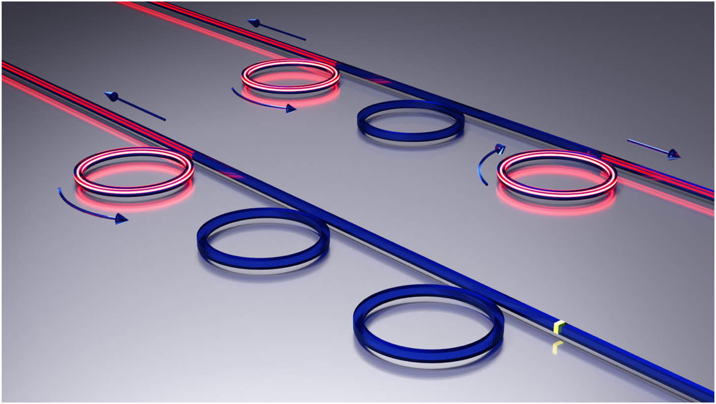
In this paper, we build on the approaches by Zhong et al. [35] and Wang et al. [32] and develop them further. In contrast to their works, we construct higher-order EPs with an easy-to-realize and robust fabrication scheme where a fine tuning of parameters is not necessary. Our proposed setup is supposed to work at room temperature and is scalable in size. In particular, we investigate two setups of WG-coupled microring cavities that form an EP of order by placing a mirror at one end of a WG. One of these setups with cavities and the corresponding eigenmodes of an is illustrated in the front of Fig. 1. The analog setup without a mirror is visualized in the background. In contrast to the proposed scheme, the mirrorless setup is at two with similar eigenmodes. We show that systems consisting of WG-coupled microring cavities with mirror-induced asymmetric backscattering enable an EP-enhanced particle sensing with an interesting and potentially useful cavity-selective scaling of the sensitivity.
Figure 1.Illustration of different setups with the corresponding eigenmodes for the realization of higher-order EPs. In the front is an example for an realized with the proposed scheme consisting of three WG-coupled microrings and a gold mirror. The setup in the background with three WG-coupled microrings is at two . The arrows show the traveling direction of the confined light.
Within coupled-mode theory, an effective Hamiltonian as a matrix is constructed, which allows for an intuitive understanding of the EP formation. In addition, the effective Hamiltonian description has an excellent agreement with the numerical finite-element method (FEM) simulations of the system including the complex eigenfrequencies and the reflection spectra of the system perturbed by a TP.
The paper is organized as follows. In Section 2, the system of two WG-coupled cavities is revised. In Section 3, the two schemes for the higher-order EP construction are discussed. A summary is given in Section 4.
2. TWO WG-COUPLED MICRORING CAVITIES
First, some preliminary considerations using a matrix model are in order. A single microring cavity is assumed, which is coupled to a WG. This situation is very well described by an effective two-mode Hamiltonian in the basis of CCW and CW propagating waves as where is the complex frequency of the CCW and CW waves. The complex off-diagonal elements reflect the small symmetric coupling between CW and CCW waves due to the weak backreflections at the WG. Adding a small TP to the cavity is typically described by a perturbation matrix. An approach for the design of such a perturbation matrix for an isolated microdisk perturbed by two TPs is given in Ref. [39]. Here, we interpret the WG already as one of the TPs leading to the matrix in Eq. (1). Thus, adding a TP to the WG-perturbed cavity adds a perturbation matrix of the following form: where is the azimuthal mode number of the mode to be perturbed and is the angle between the WG and the TP. The complex parameters and include the perturbation strength induced by the TP. Usually is much smaller than . For small perturbations, i.e., small radii of the TP, the parameter is negligible. Therefore, where the perturbation strength scales with . This statement is in agreement with Zhong et al. [30] and further reviewed in Appendix A.
Hence, the eigenvalues of the perturbed system have a splitting, which increases linearly in for . Note that this is the typical observation as is often negligibly small.
The extension of the matrix model to a system with two identical microring cavities coupled via a WG is straightforward; see Fig. 2(a) and Ref. [32]. In the basis of CCW/CW waves of the left and CCW/CW waves of the right microring, the effective Hamiltonian reads Due to the spatial symmetry of the WG-microring system, the complex coupling parameter is the same for CCW waves from the right to the left cavity and for CW waves from the left to the right cavity. It is assumed that the symmetric internal backscattering at the WG is small compared to the directional coupling from one cavity to the other implying holds. In particular, this condition is fulfilled close to the critical coupling regime. For the idealized case , the effective Hamiltonian [Eq. (5)] has two with eigenvalue and associated eigenstates . Thus, two microring cavities coupled via a WG realize in a good approximation an EP; see Ref. [32].
If a perturbation of a higher-order is considered, the frequencies diverge along the Riemann sheets of an th-order root. Therefore, the generalization of the splitting from Eq. (4) to more than two frequencies is not straightforward. In this paper, we use the convenient definition, which is the maximal distance in the complex plane between two frequencies emerging from the EP for a given perturbation; see Fig. 3 for an illustration. The definition is consistent with Eq. (4) and captures the characteristic behavior of the frequencies around an .
Figure 2.(a) Illustration of two WG-coupled microrings. The WG is infinitely long without backscattering as indicated by the outward pointing arrows. (b), (c) Frequency splitting for the matrix model of two WG-coupled microrings that are perturbed by TPs according to Eqs. (7) and (8). The parameters are , , , , and . In (b) ; in (c) . Gray solid, dashed, and dotted lines serve as guides to the eye for the respective scaling.
For the purpose of TP-sensing, it needs to be distinguished at which cavity a TP is placed. The perturbation matrix for a TP at the left or at the right cavity can be constructed via or , respectively. Thus, the effective Hamiltonian of the system with one TP at the left cavity reads with from Eq. (5). In contrast, placing two identical TPs at each cavity leads to the effective Hamiltonian, These two scenarios lead to a different behavior of the splitting as shown in Fig. 2. For this idealized case with [see Fig. 2(b)], the system shows the expected square-root scaling of the splitting at an if it is perturbed by two identical TPs, one at each cavity. A closer look at the analytic solution of the eigenvalue problem with the Hamiltonian for the exemplary parameters reveals that for the eigenstates are with a dominant square-root scaling of the corresponding eigenvalues. If is not fulfilled, the linear scaling of the eigenvalues is dominant. The transition from a square-root to a linear scaling of the splitting is only present for symmetric perturbations of both cavities. Placing a single TP solely at the left cavity represents a non-generic perturbation [25] within which only a linear scaling of the frequency splitting can be observed for over the whole range. To understand this behavior, the solution of the eigenvalue problem with for parameters in Eq. (7) is useful. It shows that, through the perturbation, an with eigenvalue and eigenstate independent from is formed. This means that the perturbation forms an and moves the system along a corresponding exceptional surface [35,36] only changing the remaining eigenvalue and eigenstate . Remarkably, if is chosen small but still finite to break the symmetry, the eigenstates approximately coalesce to , which indicates that the system is close to an in parameter space.
Figure 3.Illustration of the perturbation-induced splitting around an with frequency . For an increasing perturbation strength the complex frequencies (dots) diverge from the EP. The splitting is defined via Eq. (6) as the largest distance between two of the six frequencies for a given perturbation.
For small but finite , interesting differences can be observed as shown in Fig. 2(c). One of the differences is the quartic-root scaling of the splitting by placing a TP at the left cavity. In order to get an understanding for the observation, the matrix related to the parameter can be apprehended as another perturbation. The combination of the and perturbation leads the system being near an even though the system itself without TP only supports two . The finite and in parallel excite the quartic-root scaling the most for a parameter range around . Note that this quartic-root, however, does not lead to an increased sensitivity as splitting for is smaller than the splitting for ; see Fig. 2(c).
As mentioned before, if is not fulfilled, the system is not close enough to an in the parameter space; therefore, the linear scaling of the splitting becomes dominant. For , the TP-induced perturbation is negligible compared to the small symmetric coupling . Therefore, the observed saturation in Fig. 2(c) for small perturbation strength occurs. It is remarkable that the saturation value in is orders of magnitudes larger than itself, whereas in the single-cavity case it is of the order of . Here, the analytic solution of the eigenvalue problem with in Eq. (5) can provide an explanation: the eigenvalues are and . Thus, for small , the splitting is of the order , i.e., the square root leads to the differences in magnitudes for the saturation values. For the case with two identical TPs on each cavity, the difference between Figs. 3(b) and 3(c) is the saturation effect for negligibly small TPs.
As will be discussed in the next section, already an infinitesimal small, asymmetric coupling between CCW and CW waves in the form of a single TP at one cavity could lead to the formation of a higher-order EP. However, the scaling of the frequency splitting of the system is strongly related to the perturbation. In the example above, it is illustrated how the interaction of two perturbations, namely and , can lead to an interesting scaling behavior of .
Next, a numerical simulation to verify the matrix model of the WG-coupled cavities is in order. Therefore, the FEM solver COMSOL Multiphysics [40] is used to find solutions of the mode equation, for the quasi-two-dimensional geometry of the WG-coupled microrings; is the dimensionless complex frequency, is the complex wavenumber, and is the effective refractive index. In the simulation, we specify transverse magnetic polarization where represents the component of the electric field. The outer radius of the mircorings is set to μ, and the width of the microrings is , the same as the width of the WG . The edge-to-edge space between the microring and WG is , and the edge-to-edge distance between the two rings is . The refractive index of the microrings and WG is , and in the surrounding is set to unity. For this setup, four quasi-degenerate modes with can be calculated numerically. The perturbation is simulated via TPs with variable radii and fixed refractive index . The TPs are placed with an angle and a fixed edge-to-edge distance to the microring. From now on, the perturbation strength is defined as . As shown in Fig. 4, the results from the FEM simulation are in very good agreement with the matrix model. In particular, the correct saturation for is observed as well as the scaling in the intermediate regime with or . For larger , deviations from the matrix model arise. This is, however, expected as such a relatively large TP is no longer a localized perturbation to a microring, which is assumed in the perturbation matrix in Eq. (2).
Figure 4.Frequency splitting [Eq. (6)] for two WG-coupled microring cavities calculated with FEM simulations.
For the WG-coupled cavities without TP, one of the four mode patterns is shown in Fig. 5. Note that the computational domain is adjusted to the geometry for all the simulated structures in the manuscript, which reduces the FEM grid by 10 to 25 percent compared to a comprising rectangular domain. In the mode pattern in Fig. 5, a finite does not lead to a deviation from the idealized case that can be observed by eyes. Thus, all four mode patterns look almost identical and consist of a CCW wave in the left ring and a CW wave in the right ring, which is consistently described by the two eigenstates of the Hamiltonian from Eq. (5) for .
Figure 5.Mode pattern for one of the four modes with in two WG-coupled microring cavities. Red arrows indicate the propagation direction of the field. The colormap in the simulated domain ranges from blue to yellow.
It should be noted that the mechanisms leading to a finite backscattering can be diverse. One is the already mentioned backscattering at the WG. In a realistic experimental implementation, the backscattering might also arise from fabrication tolerances and sidewall roughness. But even in the full numerical simulations, a finite simulation domain, a finite FEM mesh, or even computations with machine precision could lead to a finite [31]. The latter seems negligibly small as the machine precision is of the order . However, a naïve estimate shows that at an this could lead to an induced splitting, .
3. CONSTRUCTION OF HIGHER-ORDER EPS WITH WG-COUPLED CAVITIES
Previous works in Ref. [35] have demonstrated that a single cavity can be tuned into an by coupling it to a WG with a mirror on one end as such a mirror leads to a fully asymmetric coupling between CW and CCW waves in the microring. In this section, we construct systems of microring cavities that exhibit an EP of order . In particular, we discuss two implementations: (i) cavities that are all coupled to the same WG [32], which has a mirror at one side, and (ii) cavities that are coupled via WGs [41], where only one WG has a mirror at the end. Both implementations have in common that the WG introduces a directional coupling between the cavities as, e.g., a CCW mode in a cavity only couples to the CW or the CCW mode of the next cavity but not to both CW and CCW. Then the mirror at the WG end introduces an asymmetric coupling between CCW and CW waves.
Note that a recent publication by Liu et al. [34] proposed a setup to implement a higher-order exceptional surface with microring cavities that, at first glance, looks similar to our proposed schemes. However, our schemes offer two main advantages. (i) The asymmetric backscattering is induced globally as it comes from a single mirror at one WG, whereas in Ref. [34] at each cavity an auxiliary WG element for the asymmetric backscattering is placed. (ii) In Ref. [34], the position of the auxiliary WG elements needs to be tuned for the backscattering to be fully asymmetric. In contrast, our setups are rather robust against the exact position of the mirror. Further note that the authors of Ref. [34] focused on the lasing properties of the system, whereas the goal of this section is the frequency splitting and characteristic behavior of the mode pattern induced by an external perturbation to the system.
A. Cavities Coupled to One WG with a Mirror
The setup for microring cavities horizontally coupled via a single WG with a mirror is shown in Fig. 6(a). For the simulation of the system, we use the same parameters as in Section 2. The mirror is realized with a slit of gold with refractive index . The slit has a width and is placed right to the center of the most right cavity and introduces a backscattering coefficient . By simulating a TP at the most left cavity in the respective -cavity setup, the characteristic th root scaling of the frequency splitting at an can be observed in Fig. 6.
Figure 6.(a) Illustration of the setup with microring cavities coupled to one semi-infinite WG with a mirror at the right-hand side. (b) The frequency splitting due to a TP with radius at the leftmost cavity is shown. As a guide to the eye the scaling with is shown from bottom to top for (solid) , (double dashed–dotted) , (dotted) , (dashed–dotted) , and (dashed–double dotted) .
Exemplary, the three-ring setup is considered. The effective Hamiltonian in the basis of CCW and CW waves in each microring is constructed as where it is assumed that a cavity couples solely to its neighbor. The coupling to the next but one cavity can be neglected. This assumption is valid, e.g., under critical coupling. For the ideal case , the effective Hamiltonian has one eigenvalue and a single eigenvector indicating an with a pure CCW eigenstate in the leftmost microring. The role of the mirror-induced asymmetric backscattering can be seen even more obviously by reordering the traveling-wave basis such that the first three components are the CCW waves in cavities 1, 2, and 3, and the second three entries represent CW waves in cavities 3, 2, and 1; the cavities are counted from left to right. Then the effective Hamiltonian assuming reads which for any represents an . It also shows that the system without a mirror at the WG has two but is arbitrarily close to the . The structure of in Eq. (11) is similar to the structure of the Jordan normal form and appears also in the context of the Hatano–Nelson model of a cylindrical superconductor [42], where it can be understood as the nonperiodic, fully asymmetric limiting case [25].
The formation of the is confirmed by FEM simulations of the dielectric structure as shown in Fig. 7 where the mode pattern of one of the calculated modes is presented. A difference to the other five mode patterns cannot be observed by eyes (not shown) due to the extreme non-orthogonality.
Figure 7.Mode pattern at the for 3 microring cavities coupled to one WG with a gold mirror at the right side. Red arrows indicate the propagation direction of the field.
For single-particle sensing, three cases can be distinguished. The TP can be placed from left to right at cavity 1, 2, or 3 as indicated by the symbols in Fig. 8(a). These three cases lead to a different perturbation matrix , , or [in the basis used in Eq. (10)]. In the parameter space, these three cases represent selected perturbation direction, which in the ideal case of results in a frequency splitting according to , , and , respectively. This cavity-selective scaling of the splitting is confirmed by FEM simulations of the dielectric structure as shown in Fig. 8(b).
Figure 8.(a) Illustration of three microring cavities coupled to one semi-infinite WG with a gold mirror at the end. The position of a TP is indicated by colored symbols. (b) The frequency splitting due to a TP with radius at cavity 1, 2, or 3 is shown by dots. As a guide to the eye, the scaling with is shown from bottom to top for (dashed) , (dotted) , and (dashed–dotted) .
The second setup to generate an EP of order utilizes vertically arranged cavities that are coupled via WGs; see Fig. 9(a). The most upper WG has a mirror at a specific end that induces an asymmetric backscattering between CW and CCW waves in the adjacent cavity. The most lower WG is placed to have the same WG-induced internal backscattering for each of the cavities. To verify the respective order of the EP, a TP at the most lower cavity is placed. As shown in Fig. 9(b) systematically, the expected scaling of the frequency splitting can be observed for a variation of the TP radius. In addition, a cavity-selective scaling of the frequency splitting is shown in Fig. 9(c) for a four-ring setup.
Figure 9.(a) Illustration of four WG-coupled microring cavities. The WGs are infinitely long without backscattering except for the most upper WG that has a mirror at one end. (b) The frequency splitting due to a TP with radius at the most lower cavity is shown. (c) For a four-microring setup the splitting due to a TP at cavity 1, 2, 3, or 4 (from bottom to top) is shown. Filled symbols are results from the FEM simulation. The corresponding open symbols are calculated from the effective Hamiltonian. The lines in (b) and (c) serve as guides to the eye and represent the scaling with (solid) , (double dashed–dotted) , (dotted) , (dashed–dotted) , and (dashed–double dotted) .
The effective Hamiltonian describing the four-ring setup in the basis of CCW and CW waves from the lowest to the upper cavity reads For , the Hamiltonian is at an with eigenvalue and eigenvector that represents a pure CW wave in the bottom-most cavity. This can be seen well in the FEM simulations in Fig. 10. Progressing to a finite , , and (see Appendix B) allows us to capture the correct splitting including the cavity-selective sensing with , , , or for a TP at cavity 1, 2, 3, or 4 (from bottom to top respectively); see Fig. 9(c).
Figure 10.Mode pattern at the for four microring cavities coupled via WGs and a gold mirror. Red arrows indicate the propagation direction of the field.
Next, the behavior of the mode patterns for a TP perturbation at a given cavity is analyzed. Therefore, the intensity for each of the eight mode patterns in the cavity is calculated numerically by integrating the mode pattern. Additionally, performing an average over the eight modes gives the averaged intensity in cavity as The intensities are then normalized to give relative intensities, i.e., . The behavior of these relative intensities is shown in Fig. 11 for a variation of the TP radius and a perturbation of each cavity. For very small TP radii, the intensities converge to the mode pattern at the (see Fig. 10), where (almost) all intensity accumulates in cavity 1. Increasing the TP radius leads to an exponential redistribution of the intensity. In cavities 2, 3, and 4, it exponentially increases with the perturbation strength while the relative intensity in cavity 1 decreases. The exponent of the exponential redistribution depends on the cavity where the TP is placed. Calculating the relative intensities from the effective Hamiltonian by analyzing its eigenvectors gives again an excellent agreement to the FEM simulations.
Figure 11.Relative intensity in each microring averaged over the eight modes in a four-ring setup perturbed by a TP is shown. The cavities are counted from bottom to top [(d) to (a)] in correspondence to the cavity position in Fig. 10. Filled symbols are results from the FEM simulation for a TP at a given cavity. The corresponding open symbols are calculated from the effective Hamiltonian.
In practice, the position at which a TP interacts with a given cavity might not be controlled precisely. Therefore, Fig. 12 shows the eigenfrequency trajectories for a two-ring and four-ring setup if the angle of the TP is varied. Since the azimuthal mode number is , a variation of from to represents a nearly periodic perturbation leading to a characteristic cyclic rotation of the eigenfrequencies in complex plane, which is referred to as chirality of an [43,44]. For larger TP radii, the eigenfrequency trajectories get deformed until eventually one or two frequencies split and form their individual cyclic behavior in the complex plane. Although such a behavior is a change in the topology of the eigenfrequency trajectories, it is very well described by the effective Hamiltonian (see Fig. 12). Consistently with the sensitivity at a higher-order EP, the separation of such an eigenfrequency trajectory happens for the four-ring setup at smaller TP radii as for the two-ring setup [cf. in Fig. 12(e) and in Fig. 12(j)].
Figure 12.Eigenfrequencies in complex plane for (a)–(e) four-ring and (f)–(j) two-ring setups [see Fig. 9(a)]. The color represents a variation of the TP angle from to with being the azimuthal mode number. The TP is placed at the most lower cavity. From left to right the radius of the TP is increased. Filled dots are results from the FEM simulations. Open circles are calculated from the effective Hamiltonian. The markers lie nearly on top of each other.
Additionally, the effective Hamiltonian allows for a calculation of the reflection spectra if the system is excited with a (real-valued) frequency at a WG [26,45,46]. To do so, the effective Green’s function, is calculated, where is given as a matrix with for the system of the WG-coupled cavities [see Eq. (12)] and represents the perturbation by the TP at the bottom-most cavity (cf. Appendix B). Consequently, also the Green’s function is given as a matrix of the same dimensions as the effective Hamiltonian . For the reflection spectra, we consider a monochromatic wave with frequency entering from the left side of the bottom-most WG. Such a wave couples to the adjacent first cavity exciting a CCW wave. In the traveling-wave basis, the excitation is, therefore, described by a vector with only one nonzero element in the first component. On the other hand, the light that leads to the reflected intensity in the most lower WG comes from the CW propagating wave in the first cavity, which is described by the second component of a vector in the traveling-wave basis. The matrix element of the Green’s function connects the CCW waves to the CW waves in the most lower cavity. Thus, the reflection spectra are obtained as [26] In Fig. 13, it is demonstrated that the reflection spectra from Eq. (15) are in a very good agreement with the FEM simulations for a four-ring setup and a two-ring setup and different positions of the TP.
Figure 13.Reflection spectra for the (a) two-ring and the (b) four-ring setups are shown [see Fig. 9(a)], with a TP at the respective most lower cavity. The angle is varied from to with . The TP has a radius . Solid curves are the full numerical results and dashed curves are computed with the effective Hamiltonian.
Depending on the TP position , individual peaks can be seen in the four-ring setup in Fig. 13(b) compared to a broad peak in the two-ring setup in Fig. 13(a). The reason is that the four-ring setup supports narrow peaks for the modes, whereas in the two-ring setup, the peaks associated with the modes are more broad and, therefore, overlap. Note that in order to separate the peaks of individual modes, it is also possible to add gain to the microrings. This typically results in more narrow peaks of the associated modes such that the modes can be distinguished in the spectrum.
However, narrowing of the peaks in the spectrum can already be seen in the passive systems without TP as shown in Fig. 14 (cf. [24,47]). The peaks in the reflection spectra are described by powers of a Lorentz curve . Each additional cavity increases the order of the EP by 2, which gives an additional term of order in the Green’s function at the [1,25,48], where and for . Thus, the reflection peaks in the -ring setup are described by . Consequently, the four-ring setup shows more narrow peaks than the two-ring setup, which are then more likely to be separated rather than overlapping for a given perturbation. Note that the exponent of the Lorentzian response is the same as the order of the EP if the effective excitation is generic, i.e., [25]. The line shape might differ for non-generic excitation and different output channels [41].
Figure 14.Reflection spectra for a setup with microring cavities at an [see Fig. 9(a)]. Colored curves are results from full numerical simulations. Dashed curves represent a fit with the powers of the function .
In this paper, we demonstrated two schemes for a handy and robust implementation of higher-order EPs with WG-coupled microring cavities. To do so, we synergized two approaches, namely the directional coupling of cavities via a WG [32] and the induced asymmetric backscattering from a mirror at the WG [35]. Thus, in a system of cavities, an EP of order is realized without complicated fine-tuned parameters. The order of the EP is verified by TP sensing. It is remarkable that the sensitivity is cavity-selective. Therefore, the induced frequency splitting not only depends on the perturbation strength, i.e., the size of the TP, but also on the cavity at which it interacts with the system. Conclusively, the WG-coupled microcavities are ideal systems to implement and study non-generic perturbations at higher-order EPs. An effective Hamiltonian based on coupled-mode theory is used to motivate the formation of the EPs as well as the sensing properties of the systems including the reflection spectra. Therefore, the effective Hamiltonian approach has been proven as an intuitive and insightful description of such systems at an EP of second or higher order.
A topic controversy discussed in recent literature is the signal-to-noise ratio of EP-based sensors. Some works indicate no enhancement of the signal-to-noise ratio at EPs [49–52], whereas others clearly show an enhancement [15,53]. Our proposed setup might be interesting for future studies on this topic due to its simplicity and versatility to perform measurements at different WG ports.
Furthermore, recent works such as Ref. [34] show an increasing interest for the use of EP and exceptional surface physics in photonic devices. Recently employed experimental platforms range from rather conventional InGaAsP single and multiple quantum wells [18,54,55] to erbium ions [10], polymers [56], and perovskites [34], underlining the timeliness and versatility of EP photonics.
Acknowledgment
Acknowledgment. The authors acknowledge fruitful discussions with R. El-Ganainy. SK is grateful for funding support from the Deutsche Forschungsgemeinschaft. We acknowledge support for the Book Processing Charge by the Open Access Publication Fund of Magdeburg University.
APPENDIX A: PARAMETERS OF THE PERTURBATION MATRIX
This section describes the process of determining the parameters and from the perturbation matrix in Eq. (2). The basic idea is to compare the numerically determined eigenvalues of an unperturbed system consisting of a microring and one or two WGs with the perturbed system, which includes additionally a TP of radius placed at an angle . For the azimuthal mode number and the before-mentioned choice of , the matrix in Eq. (2) is simplified because . Within the framework of the coupled-mode theory, the effective Hamiltonian of the perturbed system in the traveling-wave basis reads as where the matrix in Eq. (1) describes the effective Hamiltonian of the unperturbed system. The structure of and is equal for . Therefore, they have the same eigenbasis, namely the standing-wave basis. The matrix maps from the traveling-wave basis into the standing-wave basis. By taking the difference where , , and , we can connect this result to the numerical simulations. Hence, where are the numerically determined eigenvalues of the perturbed and of the unperturbed system.
In relation to the matrix in Eq. (3), it is said that for small perturbations arising from a TP with radius , the perturbation parameter should scale with . This behavior is illustrated in Fig. 15 where the parameters and are determined with Eq. (A4). For small , the parameter is orders of magnitude smaller than ; therefore, is negligible in the matrix in Eq. (2). The scaling of for small follows relatively close the behavior and, therefore, also the perturbation parameter .
Figure 15.Absolute values of the parameters and from the perturbation matrix with respect to radius of the TP. The line serves as a guide to the eye and represents the scaling proportional to .
APPENDIX B: PARAMETERS OF THE EFFECTIVE HAMILTONIAN
In order to determine the parameters , , , and for the effective Hamiltonian in Eq. (12), the difference between the eigenvalues of different effective Hamiltonians and the corresponding numerically determined eigenvalues is minimized under variation of the parameter subset.
The values of the parameters should be nearly independent from the number of microrings in the system because they model localized interactions between the traveling wave modes. Therefore, the two-ring setup [see Fig. 9(a)] is used to calculate the parameters. As a starting point, the system without a TP is chosen to determine . The mean value of the four eigenvalues with from the numerical simulation is set to With this choice of , only the parameter subset has to be determined. For this purpose, the two-ring setups with a TP at the upper and a TP at the lower cavity are considered. We call them and , respectively. These systems provide additional constraints for determining the parameter set . To get even more constraints, the TP radius is varied at a fixed TP position for and . For the effective Hamiltonian formalism, the variation of manifests itself as a variation from the parameters and . These perturbation parameters and are determined as described in Appendix A. All the previously mentioned constraints are parts of the set . Each element is related to or with a specific parameter configuration. The target function for the minimization reads as where the eigenvalues of the effective Hamiltonian with a specific parameter configuration are described through and the corresponding eigenvalues of the numerical simulation are referred to as . The refers to the set of all permutations of the four eigenvalues with . The part with is needed because it is not clear which eigenvalue of the effective Hamiltonian should be compared with the numerical one. If too few constraints are considered, then it is possible to find parameters that do not cover all numerically observed effects. For that reason, and are both part of the minimization process. It can be tricky to find well-suited start values for the minimization of Eq. (B2). The expectation is and . Hence, it can be beneficial to set fixed and vary over to get well-suited start values for the minimization over .
As mentioned in Section 2, the coupling parameter between CW and CCW waves in a cavity describes more than the weak backscattering at the WG. In FEM simulations, artificial surface roughness arises intrinsically due to the finite size of the mesh elements. Also a finite simulation domain could influence . It is recommended to use similar meshes and simulation domains for the minimization process to determine the parameter set .
References
[1] T. Kato. Perturbation Theory for Linear Operators(1966).
[38] D. Christodoulides, J. Wiersig, J. Yang. Non-Hermitian effects due to asymmetric backscattering of light in whispering-gallery microcavities. Parity-time Symmetry and Its Applications, 280, 155-184(2018).
Julius Kullig, Daniel Grom, Sebastian Klembt, Jan Wiersig, "Higher-order exceptional points in waveguide-coupled microcavities: perturbation induced frequency splitting and mode patterns," Photonics Res. 11, A54 (2023)