
Shijie Liu, Yuanlin Zheng, Xianfeng Chen. Nonlinear Frequency Conversion in Lithium Niobate Thin Films[J]. Acta Optica Sinica, 2021, 41(8): 0823013
- Acta Optica Sinica
- Vol. 41, Issue 8, 0823013 (2021)
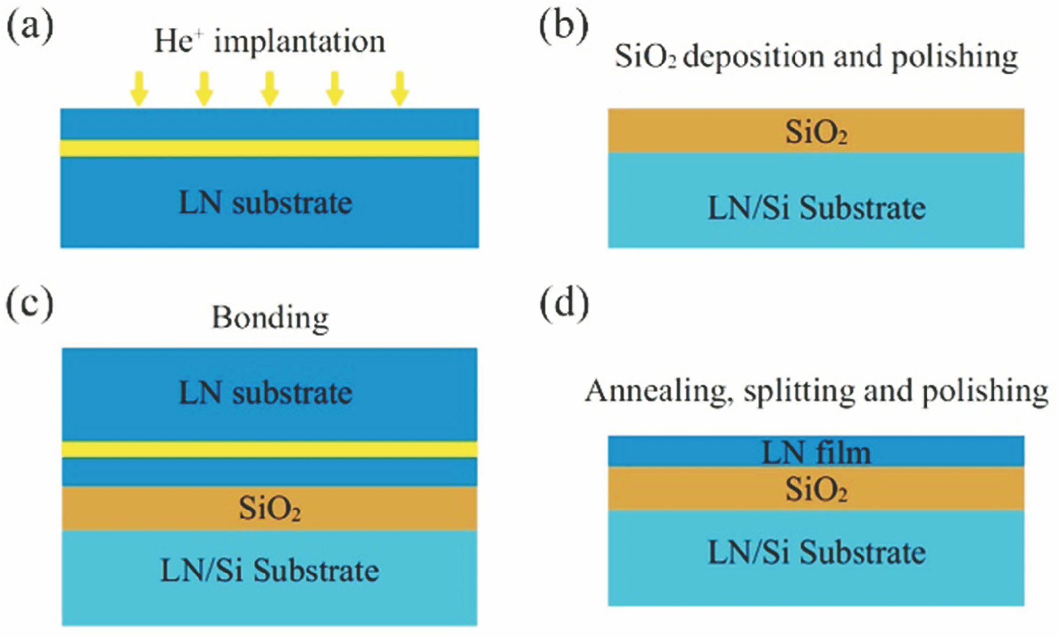
Fig. 1. Procedure of LNTF fabrication. (a) He+ implantation; (b) SiO2 deposition and polishing; (c) crystal bonding; (d) annealing, splitting, and polishing
![LN waveguides and integrated photonic chips. (a) Proton exchanged LN waveguide; (b) LNOI ridge waveguides; (c) scalar production of PIC on LNOI using ultraviolet lithography and dry etching[8]](/richHtml/gxxb/2021/41/8/0823013/img_2.jpg)
Fig. 2. LN waveguides and integrated photonic chips. (a) Proton exchanged LN waveguide; (b) LNOI ridge waveguides; (c) scalar production of PIC on LNOI using ultraviolet lithography and dry etching[8]
Fig. 3. Special phase matching mechanism. (a) Periodically grooved LN ridge waveguide[18]; (b) metasurface assisted phase matching [19]; (c) phase matching in semi-nonlinear waveguides[21]
Fig. 5. cTHG in a LNTF microdisk[24]. (a) Simulated results of mode effective index; (b)-(d) distribution of different order modes; (e) experimentally observed SHG and cTHG in the LNOI microdisk
Fig. 6. QPM schemes in LNOI WGM microresonators. (a) Cyclic variation of deff of a TE-polarized mode[25]; (b)(c) direct use of QPM in racetrack and circular microrings[26-27]
Fig. 7. PhC cavity and SHG on the LNOI platform[28]. (a) PhC cavity obtained by microscope; (b) PhC cavity obtained by SEM; (c) SHG in PhC cavity
Fig. 8. The χ(2) nonlinear processes in the LNOI microdisk. (a) SFG spectrum diagram[31]; (b) DFG spectrum diagram[32]; (c) schematic of modal-PM SFG/DFG
Fig. 9. Cascade four-wave mixing (FWM) effect in the LNOI microdisk[30]. (a) Spectrum of cascaded FWM; (b) relationship between output power and pump energy
Fig. 10. Electro-optical coupling in PPLNOI ridge waveguide[34-35]. (a) Cascade process of SH and electro-optic polarization coupling in PPLNOI ridge waveguide; (b) optical field distribution of FW light and SH light
Fig. 11. LN microring resonator and mode-locked Kerr solitons[43]. (a) Experimental schematic diagram; (b) SEM of LNOI microring; (c) cross-section diagram of waveguide mode; (d)-(h) experimental results
Fig. 12. Frequency comb generation in LNTF microresonators from electro-optic modulation[44]. (a) Schematic of LNOI microcavity and electrodes; (b) spectrum of electro-optic modulation optical frequency comb in LNOI microcavity

Set citation alerts for the article
Please enter your email address
© Copyright 2018-2021 | Chinese Laser Press. All Rights Reserved 沪ICP备15018463号-20