Y. X. Geng1、*, D. Wu2, W. Yu3, Z. M. Sheng4、5, S. Fritzsche6, Q. Liao1, M. J. Wu1, X. H. Xu1, D. Y. Li1, W. J. Ma1, H. Y. Lu1, Y. Y. Zhao1, X. T. He1, J. E. Chen1, C. Lin1, and X. Q. Yan1
1Key Laboratory of HEDP of the Ministry of Education, CAPT, and State Key Laboratory of Nuclear Physics and Technology, Peking University, Beijing 100871, China
2Institute for Fusion Theory and Simulation, Department of Physics, Zhejiang University, 310058 Hangzhou, China
3State Key Laboratory of High Field Laser Physics, Shanghai Institute of Optics and Fine Mechanics, 201800 Shanghai, China
4SUPA Department of Physics, University of Strathclyde, Glasgow G4 0NG, United Kingdom
5Key Laboratory for Laser Plasmas (Ministry of Education), School of Physics and Astronomy, Shanghai Jiao Tong University, Shanghai 200240, China
6Helmholtz Institut-Jena and Friedrich-Schiller-University, D-07743 Jena, Germany
Y. X. Geng, D. Wu, W. Yu, Z. M. Sheng, S. Fritzsche, Q. Liao, M. J. Wu, X. H. Xu, D. Y. Li, W. J. Ma, H. Y. Lu, Y. Y. Zhao, X. T. He, J. E. Chen, C. Lin, X. Q. Yan. Proton beams from intense laser-solid interaction: Effects of the target materials[J]. Matter and Radiation at Extremes, 2020, 5(6): 064402
Copy Citation Text
We report systematic studies of laser-driven proton beams produced with micrometer-thick solid targets made of aluminum and plastic, respectively. Distinct effects of the target materials are found on the total charge, cutoff energy, and beam spot of protons in the experiments, and these are described well by two-dimensional particle-in-cell simulations incorporating intrinsic material properties. It is found that with a laser intensity of 8 × 10¹⁹ W/cm2, target normal sheath acceleration is the dominant mechanism for both types of target. For a plastic target, the higher charge and cutoff energy of the protons are due to the greater energy coupling efficiencies from the intense laser beams, and the larger divergence angle of the protons is due to the deflection of hot electrons during transport in the targets. We also find that the energy loss of hot electrons in targets of different thickness has a significant effect on the proton cutoff energy. The consistent results obtained here further narrow the gap between simulations and experiments.
In the last few decades, laser-driven proton acceleration1–4 has been widely explored because of its potential applications5–10 in medicine, materials processing, radiography, and high-energy-density physics. The beams produced by this technique often exhibit unique properties, such as high brightness, short duration, and low emittance. One of the most well-established and robust mechanisms for proton acceleration is target normal sheath acceleration (TNSA).1 In this mechanism, protons are accelerated from the rear of the target by a strong sheath electric field (of the order of teravolts per meter, TV/m) generated by the expansion of highly energetic electrons originally produced in front of the target and then transported through it. There have been extensive investigations of suitable target materials for proton acceleration in recent years. For example, it has been experimentally demonstrated that proton beams from thin solid plastic targets have higher cutoff energy and charge than those generated from aluminum targets when irradiated by laser pulses with intensities of ∼1018 W/cm2.11 To explain the experimental results, an analytical model with given material properties has been established, and this has suggested that the proton acceleration can be enhanced by a resistively induced electric field in front of the plastic target.11–13 Transport of hot electrons within the plastic target is thereby significantly inhibited and filamented, and this induces nonuniformity of the profile of the protons. This has been experimentally observed14,15 and then confirmed by a particle-in-cell (PIC) code16 based on a hierarchical N-body tree algorithm.
Previous research has been successful in explaining some aspects of the proton acceleration, such as why a proton beam from a plastic target has either higher energy or a nonuniform spot. However, to fully understand the effect of the material properties of the target on proton acceleration, materials with realistic densities need to be considered. Furthermore, simulations should also include ionization dynamics,17,18 collision dynamics,19,20 degenerate plasma states,21,22 and collective electromagnetic fields,23–25 but the required simulation capabilities have not been available. Recently, a new PIC code named LAPINS, short for “Laser Plasma Interaction for Solid”, has been developed that is based on a high-order implicit numerical scheme26 and takes advantage of newly developed ionization27,28 and collision29 dynamics models.
The ionization models incorporated into the LAPINS code include both field27 and impact ionizations. Field ionization usually dominates in laser plasma interactions, and impact ionization28 dominates in beam plasma interactions. For solid-density plasmas, as electron–ion recombination cannot be ignored, electron–ion recombination is also taken into account in the code. Also for solid-density plasmas, as these are usually partially ionized, the collision model29 should contain both elastic and inelastic collisions, and, for the latter, it should take into account ionization and excitation of bound electrons. In the code, electron–electron, electron–ion, and ion–ion interactions are modeled via the Monte Carlo technique. At low temperatures, the collision model also takes into account the effects of degeneracy30. In this approach, degenerate particles obey Fermi–Dirac statistics, and nondegenerate particles follow typical Maxwell–Boltzmann statistics. The equations of motion of both degenerate and nondegenerate particles are governed by long-range collective electromagnetic fields and close particle–particle collisions. In particular, Boltzmann–Uehling–Uhlenbeck collisions ensure that evolution of degenerate particles is enforced by the Pauli exclusion principle. To suppress or avoid numerical noises, as ionization will significantly increase the plasma (free-electron) density, in the code, a fourth-order spatial difference scheme is combined with an implicit scheme for temporal stepping in solving electromagnetic fields. This new scheme26 can completely remove numerical self-heating and significantly reduce the simulation burden by using coarse simulation grids when simulating solid-density plasmas. This code enables us to calculate coupled atomic and plasma processes for intense laser–solid interaction in a more realistic way than previous codes. Within the simulations, the ionization charge state and conductivity (or resistivity) of the target can self-consistently evolve in a precise manner according to the local plasma and electromagnetic field conditions. Different types of materials (single or alloys), such as aluminum and plastics, can now be modeled, with account taken of their intrinsic atomic properties.
In this paper, the effects of target materials on laser-driven proton acceleration are investigated, with solid targets of aluminum and plastic of varying thickness being taken as examples. Experimental measurements indicate that the total charges and cutoff energies of the protons from plastic targets are significantly higher than those from aluminum targets, and that the proton beams from plastic targets have larger beam spots than those from aluminum targets. Moreover, for both plastic and aluminum targets, there exists an optimum target thickness that provides the highest proton cutoff energy, with the cutoff energy decreasing at greater thicknesses. These findings are modeled well by the newly developed PIC simulation code.
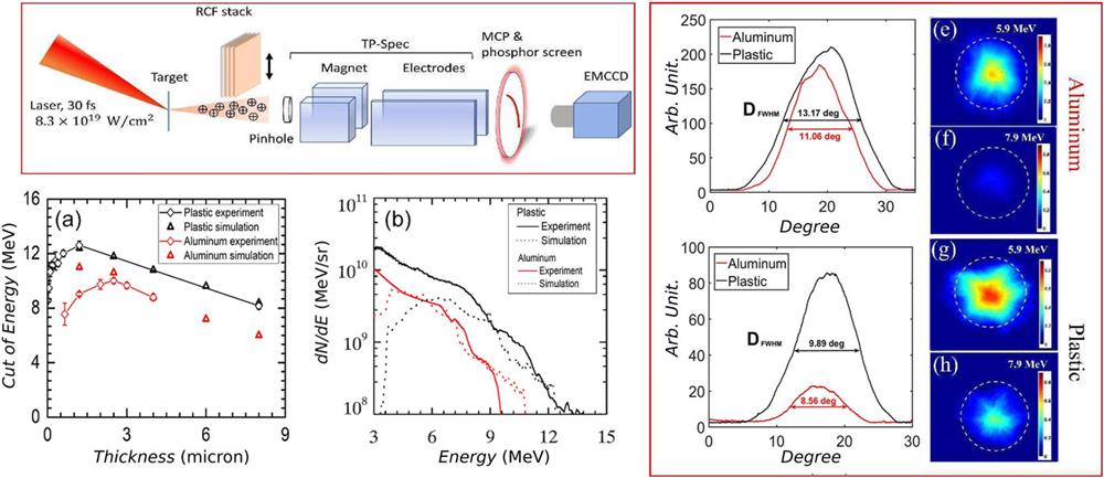
The experiments were performed at the Laboratory for Compact Laser Plasma Accelerator (CLAPA) at Peking University. An f/3.5 off-axis parabolic (OAP) mirror was used to focus the 30 fs duration and 800 nm wavelength pulses to a full-width at half-maximum (FWHM) focal spot of diameter 5 µm, containing 30% of the total laser energy (about 1.8 J), and corresponding to an intensity of ∼8.3 × 10¹⁹ W/cm2. The p-polarized pulses were incident onto different targets (aluminum or plastic) with various thicknesses at 30° with respect to the target normal. A cross-polarized wave (XPW)31 filter was introduced to enhance the intensity contrast to a ratio of 10−10 at 40 ps prior to the peak laser intensity.32Figure 1(a) is a schematic of the experimental setup. A Thomson parabola spectrometer (TPS) was located at 140 mm at the back of the target, with an entrance pinhole of 200 µm, corresponding to an acceptance solid angle of 1.6 µsr, and this was used to record the proton spectra. A multichannel plate with a phosphor screen and a 16-bit electron-multiplying charge-coupled device were used to image the parabolic ion traces. In addition, energy-resolved spatial distributions of proton beams were recorded by an attached radiochromic file (RCF) stack33 placed 40 mm behind the target.
Figure 1.(a) Experimental setup. (b) Variation of the proton cutoff energy with target thickness. The diamond symbols represent the averages of the five best shots in the experiments, and the triangles represent the results of the PIC simulations. (c) Optimum energy spectra of protons from aluminum and plastic targets detected by the Thomson spectrometer. Solid lines represent experimental results and dashed lines PIC simulations. (d), (f), (g) and (e), (h), (i) Energy-resolved spatial distributions of proton beams detected by the RCF stack for the 2.5 µm aluminum and 1.2 µm plastic targets, respectively. The white dashed circles indicate the positions of protons with a deflection angle of 14°.
Figure 1(b) shows the proton cutoff energy as a function of target thickness for fixed laser parameters and target material. The values of the cutoff energies are obtained by averaging over the five best shots for each target with the same thickness, and the error bar is the standard deviation of these five shots. Figure 1(c) shows the optimum proton spectra obtained for the two types of targets. As can be seen, the aluminum target has an optimum thickness of 2.5 µm. On the one hand, targets below this thickness are easily broken or distorted by the laser pre-pulse, and the main part of the laser pulse might interact with an under-dense plasma.34,35 The dominant acceleration mechanism would then no longer be TNSA. On the other hand, for targets above the optimum thickness, the cutoff energy is reduced. A similar trend is found for plastic targets, although the exact value of the optimum thickness has yet to be found owing to a gap (between 2 µm and 8 µm) in the thicknesses that are available with current target fabrication techniques. Nevertheless, for a large range of target thicknesses, the cutoff energies from plastic targets are always much higher than those from aluminum. The optimum cutoff energies are 9.5 MeV and 13.5 MeV for aluminum and plastic targets, respectively, as can bee seen from Fig. 1(c). It should also be noted that the total charge of the protons from a plastic target is significantly higher than that from an aluminum one, with a 2.9-fold increase in terms of the total energy [the integral of the spectra in Fig. 1(c)]. Furthermore, in Figs. 1(d)–1(i), energy-resolved spatial distributions of protons are presented for 2.5 µm aluminum and 1.2 µm plastic targets. It can be seen that the beam spots are larger for the plastic target. From a consideration of all the above experimental data, we can draw the following conclusions:
The total charges and cutoff energies from plastic targets are higher than those from aluminum targets.
The beam spots of the proton beams from plastic targets are larger than those from aluminum targets.
Greater total charges and cutoff energies from plastic targets have been observed in previous experiments,11,12 and the larger spot sizes are also consistent with previous observations,14–16 but to date there have been no interpretations that have succeeded in explaining every single aspect of the beam generation process.
To analyze the experiments, we carried out numerical simulations with the PIC code LAPINS.36–38 Even with the improved laser contrast obtained with the XPW, we still needed to deal carefully with the pre-plasma expansion caused by the picosecond pre-pulse.39 The expansion caused by this pre-pulse was calculated using radiation hydrodynamics simulations (not shown here). These simulations showed that for both aluminum and plastic targets, similar pre-plasmas with a sharp gradient of ∼0.1 µm followed by a smooth gradient of ∼10 µm were formed. In the following PIC simulation, the target was modeled as a uniform slab with the pre-plasma. To determine the effects of material properties, aluminum (density 2.7 g/cm3) and plastic (density 1.186 g/cm3 with C:H:O = 5:8:2) targets of the same thickness (several micrometers) and the same fixed pre-plasmas were considered. The simulations were carried out in a Z–Y Cartesian geometry. The size of the box was chosen as Z (50 µm) × Y (60 µm), divided into a 2500 × 3000 uniform grid. Contamination was modeled as a hydrogen layer of thickness 0.3 µm and density 1021/cm3 on the back side for both aluminum and plastic targets. The initial temperature of the solid targets was chosen as room temperature. The initial ionization degree was set at Z = 3 for aluminum and Z = 0 for plastic. Then, the ionization was fully determined by field ionization, collision ionization, and recombination. The p-polarized laser pulse irradiated the target at a fixed angle of 30° with respect to the target normal. The laser pulse had a predefined profile of the form , with r0 = 3λ0 and τ0 = 5T0, where T0 is the laser cycle. The central wavelength of the laser was 0.8 µm and the normalized amplitude a = eE/meω0c = 8, where ω0 = 2π/T0. In the Z and Y directions, absorbing boundary conditions were applied for both the particles and the laser field.
Figure 2 shows the temporal evolution of energy (transfer) into the simulation box, including laser energy entering (black), electromagnetic field energy (red), electron kinetic energy (green), and ion kinetic energy (blue), denoted by Epyt, Eem, Eele, and Eion, respectively. From their time evolution, we can obtain further insights into the whole of the laser–solid interaction process. The laser energy entering the simulation box is calculated by integrating the Poynting flux on the left boundary over time. Epyt first increases and then reaches a constant value at t = 25 fs, when the whole laser pulse has been entirely injected into the simulation box. Then, until t = 75 fs, we find that there is strong energy transfer from the electromagnetic energy Eem to the electron kinetic energy Eele and then to the ion kinetic energy Eion, which we refer to in short as the laser plasma interaction stage in front of the target. During this stage, the efficiency of coupling of the energy from the laser to plastic is significantly higher than that to aluminum. At t = 75 fs, Epyt starts to decrease, meaning that the reflected laser pulse is leaving the simulation box. The more rapid drop in Epyt shows that the reflection ratio of aluminum is significantly higher than that of plastic. After t = 100 fs, when the main body of the laser pulse has been reflected back, we can still notice a gradual energy transfer from electrons to ions, which is referred to as the thermal expansion stage and TNSA.
Figure 2.Energy (transfer) as a function of time. Data are shown for laser energy entering the simulation box (black), electromagnetic energy (red), electron kinetic energy (green), and ion kinetic energy (blue). The results from plastic targets (dashed lines) are compared with those from aluminum targets (solid lines). Here, the thickness is 1.2 µm for both aluminum and plastic targets.
In Fig. 3, the electromagnetic energy densities are presented for both aluminum and plastic targets with thicknesses of 1.2 µm. The snapshot is taken at t = 53 fs, which is a typical time within the laser plasma interaction window (from t = 25 fs to t = 75 fs). It appears that the penetration depth within the plastic is larger than that within the aluminum. Deeper penetration will significantly enhance the efficiency of energy transfer from laser to plasma through various mechanisms,40–42 typically including a J × B mechanism, vacuum heating, and direct laser acceleration. A possible reason for the greater penetration depth is the lower electron density for fully ionized plastic than for aluminum.
Figure 3.Electromagnetic energy densities for (a) aluminum and (b) plastic targets at t = 53 fs (i.e., 20T0). The solid lines indicate the initial positions of the solid targets, and the dashed lines mark the fronts of the pre-plasma. The thickness is 1.2 µm for both targets.
Figure 4 presents the kinetic energy densities of electrons, indicating the transport process of hot electrons within the solids. Although breakdown of plastic might occur as a result of the pre-pulse (currently beyond the capabilities of radiation hydrodynamics simulations), as an initial insulator, the resistivity of a plastic target is very large compared with that of an aluminum target. According to Ohm’s law E = ηJe, where η is the resistivity of the bulk target and Je is the current density of electrons, an intense resistive electric field will inhibit the transport of hot electrons. As shown in Fig. 4, when compared with aluminum targets [Figs. 4(a) and 4(b)], the inhibition and deflection of hot electron transport in plastic targets [Figs. 4(c) and 4(d)] leads to a larger hot electron spot. The inhibition also appears in Fig. 5, where the magnitude of the electric field is shown as a function of time and position. The electric field is along the normal direction of the back-side surface, starting at z = 17 µm and y = 0 µm. As can be seen, the peak value of the electric field appears at t = 105 fs for an aluminum target and t = 115 fs for a plastic target. Furthermore, we find that the electric field of a plastic target lasts for a long time when compared with that of an aluminum target. As revealed in Fig. 4, this is due to the higher energy coupling efficiency from laser to plastic than to aluminum. Moreover, we find that the electron energy density is significantly decreased during transport in both aluminum and plastic targets. This is due to deposition and energy losses of hot electrons during transport, caused by the intense resistive electric fields. With further increase in the target thickness, as the energy losses of hot electrons increase, the proton cutoff energies accordingly decrease. In Figs. 6(a) and 6(b), the magnitude of the electric field is shown as a function of time and position for aluminum targets of thickness 2 µm and 8 µm, respectively. Electron recirculation is not significant under the conditions considered here, although in general it could be important for high-contrast multi-picosecond laser pulses.43 Here, the acceleration is dominated by the very first electron bunch, and the transport of electrons and energy loss in the solid is key to understanding why the accelerating field decreases with increasing thickness (Fig. 1).
Figure 4.Electron kinetic energy distributions for (a) and (b) aluminum and (c) and (d) plastic targets, both with thickness 8 µm, at t = 53 fs (i.e., 20T0) and t = 80 fs (i.e., 30T0).
Figure 5.Magnitude of the electric field as a function of time and position for (a) aluminum and (b) plastic targets, both with thickness 8 µm. As indicated by the dashed line in Fig. 4, the electric field is along the normal direction of the back-side surface, starting at z = 17 µm and y = 0 µm.
Figure 6.Magnitude of the electric field as a function of time and position for aluminum targets of thickness (a) 2 µm and (b) 8 µm. As indicated by the dashed line in Fig. 4, the electric field is along the normal direction of the back-side surface, starting at z = 17 µm and y = 0 µm.
In Fig. 7, the spatial and angular energy distributions of protons for aluminum and plastic targets are presented at 320 fs, the end of the simulation, when acceleration reaches saturation. From a comparison with Figs. 1(b) and 1(c), it can be seen that there is remarkable agreement between simulation and experiment for both energies and beam spots. The larger beam spots from the plastic target are also reflected in the diverging angular distributions, as shown in Figs. 7(c) and 7(d). This is because, as shown in Fig. 4, divergent transport of hot electrons will lead to larger spatial spots of the accelerated proton beams, since these are accelerated mainly by the expansion of hot electrons on the back side of the target. It should be noted from our simulation at a laser intensity of 8 × 10¹⁹ W/cm2 that the energetic protons come from the rear contamination at the back surface for both types of target. This differs from what was found in previous work11–13 with an order-of-magnitude lower laser intensity and a thicker target, in which it was assumed that protons are accelerated by the resistive electric field in plastic targets. Our research indicates that the energy conversion efficiency determined by the target material properties is the key parameter.
Figure 7.(a) and (b) Spatial distribution and (c) and (d) angular distribution of proton energies for aluminum and plastic targets, both of thickness 2 µm, at t = 320 fs (i.e., 120T0). The angle ϕ is defined as ϕ = arctan(uy/uz) − θt, where θt is the target dip angle, which is 30°, and uy and uz are the proton momenta.
To summarize, we have reported experimental and numerical simulation investigations of laser-driven proton acceleration with two solid material targets: aluminum as a typical conductor and plastic as a typical insulator. The target material has been found to have significant effects on the total charge, cutoff energy, and beam spot of the protons. Generally, a plastic target produces proton beams with higher charge, higher cutoff energy, and larger beam spot than an aluminum target of the same thickness under the same laser conditions. Two-dimensional PIC simulations give a good description of the effects of the target material on the laser-driven acceleration of protons by including both ionization dynamics and collision dynamics. The results of the work reported here suggest that the use of laser–solid interaction models instead of pure laser plasma interaction in the simulation should give a closer match to experimental observations. Furthermore, this study of material effects on proton acceleration is also closely relevant to the creation of warm dense matter by intense laser pulses. The different proton beam characteristics obtained with different targets may be used as a diagnostic tool for warm and hot dense matter created by intense lasers.
[18] M. V. Ammosov, V. P. Krainov, N. B. Delone. Tunnel ionization of complex atoms and of atomic ions in an alternating electromagnetic field. Sov. Phys. JETP, 64, 1191(1986).
[38] W. W. Chang, H. Xu, H. B. Zhuo et al. Parallel programming of 2(1/2) dimensional PIC under distributed memory parallel environments Chin. J. Comput. Phys., 19, 305(2002).
Y. X. Geng, D. Wu, W. Yu, Z. M. Sheng, S. Fritzsche, Q. Liao, M. J. Wu, X. H. Xu, D. Y. Li, W. J. Ma, H. Y. Lu, Y. Y. Zhao, X. T. He, J. E. Chen, C. Lin, X. Q. Yan. Proton beams from intense laser-solid interaction: Effects of the target materials[J]. Matter and Radiation at Extremes, 2020, 5(6): 064402