• Laser & Optoelectronics Progress
  • Vol. 58, Issue 3, 3120041 (2021)
Sheng Qiming1, Zheng Gang2、*, Zhang Xiongxing2, Sun Bin2, Jing Liqiang2, and Han Yuan1
Author Affiliations
  • 1School of Electronic Information Engineering, Xi′an Technological University, Xi′an, Shaanxi 710021, China
  • 2School of Optoelectronic Engineering, Xi′an Technological University, Xi′an, Shaanxi 710021, China
  • show less
    DOI: 10.3788/LOP202158.0312004 Cite this Article Set citation alerts
    Sheng Qiming, Zheng Gang, Zhang Xiongxing, Sun Bin, Jing Liqiang, Han Yuan. Three-Channel Frequency-Modulated Continuous-Wave Laser Interferometric Displacement Measurement System[J]. Laser & Optoelectronics Progress, 2021, 58(3): 3120041 Copy Citation Text show less
    Angular frequency waveforms of different signals
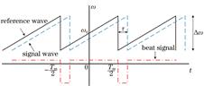
    Fig. 1. Angular frequency waveforms of different signals
    Schematic of three-channel FMCW laser interference system
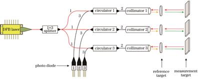
    Fig. 2. Schematic of three-channel FMCW laser interference system
    Control circuit of three-channel FMCW laser interferometer
    Fig. 3. Control circuit of three-channel FMCW laser interferometer
    Schematic of laser drive circuit
    Fig. 4. Schematic of laser drive circuit
    Circuit board for three-channel FMCW laser interference system
    Fig. 5. Circuit board for three-channel FMCW laser interference system
    Execution sequence of each chip program
    Fig. 6. Execution sequence of each chip program
    Flowchart of phase detection of beat signal
    Fig. 7. Flowchart of phase detection of beat signal
    Experimental device
    Fig. 8. Experimental device
    Beat signal before and after adding synchronization signal. (a) Before adding; (b) after adding
    Fig. 9. Beat signal before and after adding synchronization signal. (a) Before adding; (b) after adding
    Correlation of feature points before and after adding synchronization signal. (a) Before adding; (b) after adding
    Fig. 10. Correlation of feature points before and after adding synchronization signal. (a) Before adding; (b) after adding
    Scatter points of displacement errors of different channels. (a) Channel 1; (b) channel 2; (c) channel 3
    Fig. 11. Scatter points of displacement errors of different channels. (a) Channel 1; (b) channel 2; (c) channel 3
    Linearity curves of three channels
    Fig. 12. Linearity curves of three channels
    MCUWire length of clock /mmWire length of synchronous signal /mm
    MCU 149.5290
    MCU 249.53522.276
    MCU 349.53122.294
    Table 1. Routing length of each chip signal line
    Number of experimentsMean/nmStandard deviation/nm
    1-0.2896502.64858
    20.2655501.79282
    -0.6098502.52146
    3

    4

    5

    6

    -0.1635751.75456
    0.2361302.15621
    0.5963302.02113
    Average0.3601802.14913
    Table 2. Stability test results
    Sheng Qiming, Zheng Gang, Zhang Xiongxing, Sun Bin, Jing Liqiang, Han Yuan. Three-Channel Frequency-Modulated Continuous-Wave Laser Interferometric Displacement Measurement System[J]. Laser & Optoelectronics Progress, 2021, 58(3): 3120041
    Download Citation