
Dongshi Zhang, Xinzhuo Li, Yao Fu, Qinghe Yao, Zhuguo Li, Koji Sugioka. Liquid vortexes and flows induced by femtosecond laser ablation in liquid governing formation of circular and crisscross LIPSS[J]. Opto-Electronic Advances, 2022, 5(2): 210066
- Opto-Electronic Advances
- Vol. 5, Issue 2, 210066 (2022)
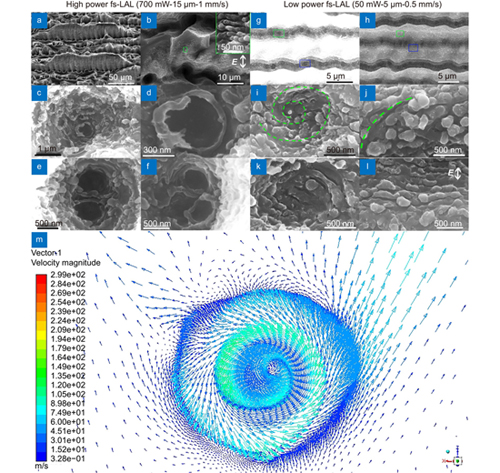
Fig. 1. (a –b ) SEM images showing the side and top views of the cracked structures obtained by fs-LAL of Si at a laser power of 700 mW, a scan interval of 15 μm, and a scan speed of 1 mm/s. (c ) Structure of a macropore. (d ) Enlarged CLIPSS morphology in (c). (e , f ) Twin CLIPSS in a macropore. (g , h ) SEM images of the grooves obtained by 50mW-fs-LAL. High contrast applied to (g) is to see macropores in the valleys of grooves more clearly. (i /k , j /l ) Enlarged images of green and blue rectangles in (g) and (h), respectively. The direction of laser polarization is shown in (b, l). (i, j, k) and (l) Irregular and normal LIPSS, respectively. (m ) Velocity vector of a fluid vortex formed in a hole structure upon the impact of high-speed superimposed horizontal and vertical flows of fluids.
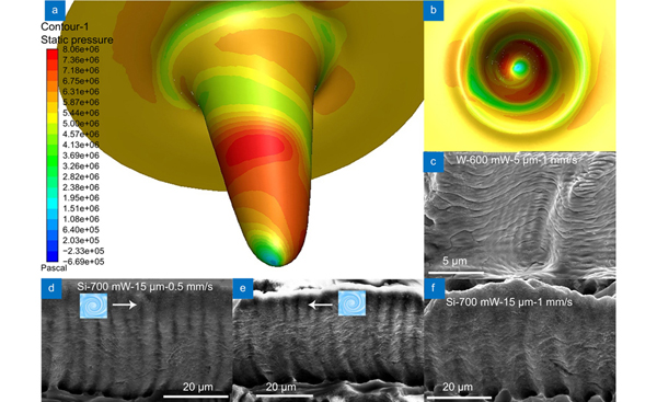
Fig. 2. (a ) Side view and (b ) top view of the static pressure distribution of the simulated liquid vortex. (c ) SEM image of the tungsten groove created by fs-LAL of W in water at a laser power of 600 mW, a scan interval of 5 μm, and a scan speed of 1 mm/s, which indicates that liquid vortexes induce a series of horizontal cracks. (d , e ) and (f ) SEM images showing the morphologies of the side walls of grooves generated by fs-LAL of Si in water at fixed conditions of a laser power of 700 mW and a scan interval of 15 μm with two different scan speeds of 0.5 and 1 mm/s, respectively. SEM images were taken from the side view with a 30° tilt.
Fig. 3. (a ) Fluidic velocity vector in four consecutive macropores upon the impact of high speed liquids from both horizontal and vertical directions, which indicates the formation of liquid vortexes on the side walls of the groove, near the openings of the macropores. (b –c ) SEM images of CLIPSS formed on the openings of the macropores which are produced by fs-LAL of Si in water under the conditions of a laser power of 700 mW, a scan interval of 15 μm, and a scan speed of 1 mm/s. (c) Enlarged morphology of the white rectangle region in (b).
Fig. 4. (a ) SEM images of CLIPSS formed on the openings of macropores which are produced by fs-LAL of Si in water under the conditions of a laser power of 700 mW, a scan interval of 5 μm, and a scan speed of 1 mm/s. (b ) Enlarged morphology of the green rectangle in (a) which indicates the convergence of LIPSS oriented in two different directions. (c ) Fluidic velocity vector of the flows while encountering a mountain-like structure like (b), which vary their directions at different heights of the structure. Simulation conditions: an enlarged mountain-like structure with height and radius of 6 and 10 μm, respectively. A small trench with a depth of 2 μm is located beneath the mountain-like structure. The simulation model is a little enlarged compared with the structure shown in (b), which is aimed to ensure different directional flows on different parts of the structures to be seen more clearly. The starting flow is horizontal from top right to bottom left at a speed speed of 5 km/s.

Set citation alerts for the article
Please enter your email address
© Copyright 2018-2021 | Chinese Laser Press. All Rights Reserved 沪ICP备15018463号-20