1Shanghai Key Laboratory of Materials Laser Processing and Modification, School of Materials Science and Engineering, Shanghai Jiao Tong University, Shanghai 200240, China
2RIKEN Center for Advanced Photonics, 2-1 Hirosawa, Wako, Saitama 351-0198, Japan
3School of Aeronautics and Astronautics, Sun Yat-sen University, Guangzhou 510275, China
4State Key Lab of Metal Matrix Composites, School of Materials Science and Engineering, Shanghai Jiao Tong University, Shanghai 200240, China
Dongshi Zhang, Xinzhuo Li, Yao Fu, Qinghe Yao, Zhuguo Li, Koji Sugioka. Liquid vortexes and flows induced by femtosecond laser ablation in liquid governing formation of circular and crisscross LIPSS[J]. Opto-Electronic Advances, 2022, 5(2): 210066
Copy Citation Text
Orientations of laser induced periodic surface structures (LIPSS) are usually considered to be governed by the laser polarization state. In this work, we unveil that fluid dynamics induced by femtosecond (fs) laser ablation in liquid (fs-LAL) can easily break this polarization restriction to produce irregular circular-LIPSS (CLIPPS) and crisscross-LIPSS (CCLIPSS). Fs laser ablation of silicon in water shows formation of diverse LIPSS depending on ablation conditions. At a high power of 700 mW (repetition rate of 100 kHz, pulse duration of 457 fs and wavelength of 1045 nm), single/twin CLIPSS are produced at the bottom of macropores of several microns in diameter due to the formation of strong liquid vortexes and occurrence of the vortex shedding effect. Theoretical simulations validate our speculation about the formation of liquid vortex with an ultrahigh static pressure, which can induce the microstructure trenches and cracks at the sidewalls for fs-LAL of Si and tungsten (W) in water, respectively. At a low power of 50 mW, weak liquid vortexes are produced, which only give birth to curved LIPSS in the valleys of grooves. Consequently, it is deduced that liquid vortex plays a crucial role in the formation of macropores. Mountain-like microstructures induce complex fluid dynamics which can cause the formation of CCLIPSS on them. It is believed that liquid vortexes and fluid dynamics presented in this work open up new possibilities to diversify the morphologies of LIPSS formed by fs-LAL.
Introduction
Ultrashort (femtosecond (fs) and picosecond (ps)) pulse laser ablation/processing (UPLA/P) is occupying an increasingly important position in the manufacturing field because of some specific merits1, 2. In particular, UPLA/P can produce extremely high pressure, high temperature (HPHT) environment3-5 in atmosphere, which is not available by conventional lasers such as continuous wave and nanosecond lasers. This feature offers versatility of UPLA/P to realize surface structuring, nanomaterial synthesis and nanomaterial assembly6. Adjusting UPLA/P environment and changing the laser/processing parameters (e.g., pulse energy, pulse duration, repetition rate, scan speed, etc.3, 7), varying experimental setups8 and target materials9-10 render high flexibility to this technique, enabling synthesis of different types of nanomaterials and formation of diverse structures. As far as the surface structuring is concerned, the created structures can involve the nanoscale, microscale or multiscale, which make them applicable for different applications in the fields of catalysis, biology, optics and optoelectronics, since the structure scale highly influences surface properties such as wettabilty, adhesiveness, sensitivity, color and absorption11-16. Additionally, UPLA/P is capable of surface structuring of a large variety of materials including metals, ceramics, semiconductors, dielectrics, polymers, and two-dimensional materials17-27, which involve hard-to-treat materials26. Recent UPLA/P innovations have unveiled that new factors such as electric and magnetic fields28, 29, high-pressure shockwave30, and persistent bubbles18, 31 generated during UPLA/P or exerted externally may become new keys to manipulate structure morphologies. Despite the success in generating new types of structures at different scales, it is still challenging to further enrich the structural diversity and unveil the underlying key factors that cause the differences.
Laser induced periodic surface structures (LIPSS)32, 33 is an evergreen subject since its discovery in 196534 owing to its ease to be constructed on different materials by single-step laser irradiation/ablation for optical, eletrochemical, biological and mechanical applications32, 35. It is commonly found that low spatial frequency LIPSS (LSFL) on high-absorbance materials (metals) and low-absorbance materials (dielectrics) are oriented perpendicular and parallel to the polarization direction of the linearly polarized laser utilized16, respectively. Controlling the polarization directions of linearly polarized lasers allows flexibly manipulating the orientations of LIPSS36-38 to generate different colors on the surfaces, which opens up new opportunities for colorful paintings of metallic surfaces by programming the orientations of LIPSS39, 40. In comparison, circularly polarized laser beams often give rise to the formation of bead-strings41. Thanks to the advance in technique methodology and optics, non-linear LIPSS have already become accessible. For example, Han et al. constructed concentric semi circular LIPSS (CLIPSS) on silicon by single-pulse fs laser irradiation on the pre-processed quasi-plasmonic annular-shaped nanostructures42, where the excited surface plasmon polaritons (SPPs) triggered by laser irradiation played a key role in its formation. Romashevskiy et al. produced CLIPSS on silicon via bubble-diffracted Gaussian-beam fs laser pulses43. A series of radial- and ring-shaped LIPSS have been created by laser ablation using radially and azimuthally polarized vortex beams, respectively44-47, in which the orientations of nonlinear LIPSS are still perpendicular to the directions of local beam polarizations45. In our previous work, we showed that the orientations of high spatial frequency LIPSS (HSFL) were not strictly perpendicular to the direction of light polarization48, and possess a maximal tilt angle of 50° on the microstructures with height gradients. Both clock-wise and anticlockwise tilted HSFL were found, which converged together in a sink-like inlet and resulted in the formation of normal HSFL in the outlet48. These findings indicate that an influential factor must be triggered during fs laser ablation in liquid (fs-LAL)3, which can compromise the effect of light polarization on the orientations of LIPSS. However, to date, there is no evidence to confirm what this factor is and whether it is possible to induce CLIPSS using a linearly polarized laser without any external assistance. Tsibidis et al. proposed a hybrid model to interpret the structural evolution from LIPSS to microspikes and concluded that surface melt in combination with electromagnetic interference led to the formation of LIPSS, while hydrodynamics including Marangoni convection and counter- rotating vortex rolls led to the formation of microgrooves and microspikes49. Hence, it is deduced that liquid vortex may be generated during laser ablation in liquids, which may give birth to CLIPSS structures.
In this paper, we demonstrate the possibility to induce formation of CLIPSS or crisscross LIPSS (CCLIPSS) by linearly polarized fs laser ablation of silicon in water depending on the conditions. Macropores with a dimension in the microscale are speculated to be the ideal candidates to identify the influential factor responsible for LIPSS tilting and CLIPSS production because of the height gradients in all directions. Hence, a special attention is paid to the nanostructures in macropores formed in the valley of the grooves. Fs-LAL of tungsten (W) in water is further carried out to check how ultrahigh pressures of LAL-induced liquid vortexes influence the side walls of the microstructures. Three models including single macropore, four macropore arrays, and mountain-like bumps are established for simulation verification.
Experimental
An fs laser system (FCPA μ Jewel D-1000-UG3, IMRA America Inc., Ann Arbor, MI, USA) with a pulse duration, wavelength and repetition rate of, respectively, 457 fs, 1045 nm and 100 kHz was used for fs-LAL. A 20 × objective lens (numerical aperture (NA): 0.4, Mitutoyo, Kawasaki, Japan) was used to focus the laser beam on a single-crystalline silicon substrate placed inside a glass culture dish (diameter of 45 mm, height of 20 mm) filled with 8 mL water. The liquid thickness above the target surface was kept constant to be 5 mm. Two different laser powers of 700 and 50 mW were employed for fs-LAL of Si, while a fixed laser power of 600 mW was used for fs-LAL of W. The pulse energies for 700, 600 and 50 mW correspond to 7, 6 and 0.5 μJ, respectively. The laser spot size was estimated to be 3.4 μm based on λ=1045 nm and M2=1.1 of our laser system and NA=0.4 of the objective lens used, so the fluences for laser powers of 700, 600, and 50 mW at 100 kHz repetition rate were calculated to be around 77.1, 66.1 and 5.5 J/cm2, respectively. An area of 2 mm × 2 mm was scanned for each case using the line-by-line scanning described in ref.50. The scanning line intervals were 15 and 5 μm for 700 mW-fs-LAL of Si, 5 μm for 50mW-fs-LAL of Si and 600 mW-fs-LAL of W. A scanning electron microscope (SEM) (Thermo Fisher Scientific, Quattro ESEM, Tokyo, Japan) was used to characterize surface structure morphologies including both microstructures and HSFL with different orientations.
Selecting these experimental parameters is due to the following reasons. During the characterization of the structures generated by ablation at a laser energy of 700 mW with different scan intervals of 5 and 15 μm30, CLIPSS and CCLIPSS structures were discovered, which are the main content of this work. To prevent a repetitive description of the same results, this manuscript only displays the results about CLIPSS and CCLIPSS. To demonstrate the reproducibility of the experiments, we performed laser ablation of Si in water at the laser powers of 50 mW to see how structures evolve when weaker liquid flows are generated. Regarding the cracking phenomenon induced by liquid vortexes during ablation of W, we have already reported the morphology of 600mW-laser ablated W51 and Si48. Our previous works reported the interesting discovery of abnormally oriented LIPSS on height-gradient microstructures48, but the mechanism for this abnormal phenomenon was only speculated based on previous LIPSS formation mechanisms. This work is well supplementary to our previous works because it for the first time reveals the impact of liquid flows on LIPSS formation.
Simulation
The simulation does not consider the impacts of shockwaves and laser-matter interactions. We only assume the liquid moving velocity is the same as that of the shockwave. The reason for the simple modeling is because of the high complexity of multi-pulse ablation in liquids, including generation and quenching of plasma, shockwave reflection52, generation and collapse of bubbles53, light reflection/refraction by bubbles18, 54, surface oxidation and excited surface plasmon polaritons (SPPs)55. No matter which complex condition is formed, a high-speed shockwave must be produced by laser ablation and will serve as the driving force for the generation of liquid flows. The lifetime of shockwaves is around 200 ns56. The distances between adjacent grooves are 5 and 15 μm. The shockwave speed is ~5000 m/s57. This means that after 1 and 3 ns, the shockwave will be reflected between adjacent grooves, which should be strong enough to induce the high-speed flow among the grooves. The lifetime of molten layers (the precursors of LIPSS) is longer than 30 ns in the case of laser ablation in air58. In water, benefiting from liquid cooling, the lifetime of molten layers is reduced to several ns59. From the perspective of timescale, surface melting, SPPs and shockwave propagation can take place simultaneously. Therefore, the simulation in our study corresponds to the experiment to some extent, with a focus on the influence of fluid flows on different structures in a molten state (precursor of LIPSS48, 60) in the presence of SPPs excited by laser ablation.
Traditional simulation methods are not suitable to realize an ultra-high-speed fluid simulation in the microscale because very rigorous laws in the microscale have to be employed. In the case that the basic assumptions and axioms established by the basic framework of continuum mechanics cannot be fully satisfied, the rationality of amplification method is strongly illustrated. With the same Reynolds number (Re) and Knudsen number (Kn), the internal flow fields of the microscale sample and the amplified milliscale sample have a high similarity. Therefore, in our simulation, for simplicity, we used the amplified milliscale models to simulate the microscale fluid mechanics in the extreme environment of ultra-high-speed water flows. Re is a non-quantitative number that can be used to characterize fluid flow. When Re is small, the influence of the sticky force on the flow field is greater than the inertia, so that the disturbance of the flow rate in the flow field will be attenuated by the viscous force. The fluid flow is stable, which is normally a stratospheric flow.Kn represents the ratio of the average free range of molecules to the characteristic lengthL of an object in the flow field. Kn and Re can be calculated using the following equations
where λ is the free path of the molecule, L is the geometric feature scale which is set as the macropore size and groove depth, Kb is the Boltzmann constant, σ is the molecular diameter, p is the fluid pressure, i.e. qualitative pressure of Kn, and T is the fluid thermodynamic temperature. The Kn is mainly determined by geometric scale and fluid pressure. The domain outlet fluid pressure was selected as the qualitative pressure of the small macropore fluid Kn. In Eq. (2), μ is the kinetic viscosity of a fluid, which is set as a constant for simulation. ρ is fluid density, u is fluid characteristic speed, L is geometric feature, mr is mass flow. Recan be changed by changing the fluid characteristic speed u.
Under the continuous medium condition, when the Reynolds number of the microfluid and its amplified milli-scale fluid are equal, they have proven to possess very similar flow characteristics61. Hence, in this work, we performed the simulation of the magnified milli-scale model under the continuous medium hypothesis with the same Knudsen number, to solve the difficulties of grid generation and convergence for micron scale structures. The full size of model was about 10 μm according to the sizes of macropores published in our previous report30. The parameters for the amplified milli-scale simulation models were set atL =10 mm, u = 5 m/s, and p =1.01×10³ Pa. In reality, the pressure of fluids should vary with time and structures. Shockwave reflection between the grooves will complicate the flow direction and pressures. Considering a pulsed laser with a repetition rate of 100 kHz used in this study, the time interval between two successive pulses is 10 μs, which is much shorter than the lifetime of cavitation bubbles generated during laser ablation in liquids62. This means that subsequent pulses will hit the cavitation bubbles to induce their breakdown, while the bubbles will also reflect/refract the laser beam18, 54, making the processes very complex. The collapse of cavitation bubbles also generates shockwaves63, which may also influence the pressure of liquid flows. Hence, for simplicity, we assume that the fluid is kept always at a constant pressure for simulation. Since the shockwave is formed after plasma quenching3, the temperature of liquid flow induced by the propagation of shockwave is assumed to be room temperature.
The fluid medium was water. The Kn value was calculated to be ~10–13 according to the geometric and pneumatic parameters. Kn is generally used to determine whether the fluid is suitable for the continuous assumptions. It is generally believed that when Kn is smaller than 0.001, the liquid flow can be categorized as a continuous medium64. According to Kn value we calculated, the liquid flow induced by strong shockwaves can be categorized as a continuous medium. Hence, three hypotheses for Navier-Stokes equation are met, including linear relation between stress tension and strain rate tension, isotropic fluid and zero stationary fluid strain rate.
Navier-Stokes equation:
Reynolds average of Navier-Stokes equation, we can get:
where is liquid density, is hydrostatic pressure, is speed component, is mass force, is dynamic viscosity coefficient, is Reynolds stress. Because of the presence of Reynolds stress, this equation is not closed. To make the equation closed and for the sake of computational efficiency, the following RNG K-ε turbulent model (k equation) is adopted.
Turbulent kinetic energy equation of K-ε turbulent model is:
where is turbulent viscosity term, , , , are turbulent kinetic energy production terms.
Considering the flow on the microscale structures had a strong pressure drop and compressibility and the viscosity force changed significantly with increasing the flow surface area to volume ratio, the enhanced wall function was selected. Wall surfaces were set as the non-slip boundary condition for simulation. We used the Leap Squares Cells Based method to make the gradient item in equation (3) discrete, and adopt the second-order precision upwind format to make N-S equation and K-ε turbulent model discrete. The tolerance of convergence criteria is 10–4 for our simulation.
Laser ablation in liquid normally induces the formation of stress waves in the ablated solid target and shockwaves in liquids65, which are the driving forces for the breaking of brittle structures. The propagation of shockwaves may push the liquid to flow horizontally on the surfaces, which is deemed to be the dominant flow driving force. The water flow is driven by the laser induced shockwaves at a speed of ~5000 m/s57, which is assumed to be the same as the speed of liquid flows generated by fs-LAL in water for simulation. During laser ablation, water breakdown also takes place in the beam path, leading to the formation of many nanobubbles66. The collapse of these nanobubbles induces the formation of another series of shockwaves and results in the formation of vertical liquids flowing towards the ablated surfaces. When small bubbles are subjected to laser irradiation, very complex Marangoni flows can be induced67, which leads to the generation of complex tilt flows along different directions. Hence, superimposed fluid flows coming from both horizontal and vertical directions were adopted for simulations of the flow fields on the structures. The simulation model is a little enlarged for the mountain-like structure to demonstrate the possibility of inducing crisscross flows, which is aimed to ensure different directional flows on different parts of the structures to be seen more clearly. The height and radius of the simulated mountain-like structure are 6 and 10 μm, respectively. A small trench with a depth of 2 μm is assumed to be located beneath the mountain-like structure. The starting flow is horizontal from upper right to bottom left at a speed of 5 km/s.
Results and discussion
CLIPSS
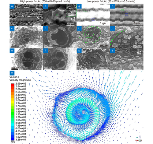
Figure 1(a, b) show the side and top views of hierarchical micro/nanostructures created by fs-LAL of Si in water at a laser power of 700 mW, a scan interval of 15 μm and a scan speed of 1 mm/s. Most grooves are broken due to the plasma confinement in them and the peening effect of strong shockwaves with the pressure amplitude of GPa3. The broken grooves are characterized by sharp edges (Fig. 1(b)), very different from the unbroken grooves48. The smoothly broken regions show a dark color, while the other regions displaying a white color are decorated by HSFL with periods of 100–200 nm (Inset image in Fig. 1(b)), which are formed due to the generation of surface plasmon polaritons68, 69. The orientation of HSFL is perpendicular to that of the light polarization, in accordance with previous reports32, 70, 71. Inhomogeneous macropores are generated in the valleys of broken grooves (Fig. 1(b)), which indicates that there is no need of multiple back-and-forth runs of fs laser ablation to generate macropores since the line-by-line scanning have been employed in this study72. CLIPSS is located in the deep macropores, as shown in Fig. 1(c–f), including both single CLIPSS (Fig. 1(c, d)) and twin CLIPSS (Fig. 1(e, f)). It is noteworthy that according to our observation, the formation of single CLIPSS and twin CLIPSS are randomly generated because of the complexity of the multi-pulse ablation conditions.
Figure 1.(a–b) SEM images showing the side and top views of the cracked structures obtained by fs-LAL of Si at a laser power of 700 mW, a scan interval of 15 μm, and a scan speed of 1 mm/s. (c) Structure of a macropore. (d) Enlarged CLIPSS morphology in (c). (e, f) Twin CLIPSS in a macropore. (g, h) SEM images of the grooves obtained by 50mW-fs-LAL. High contrast applied to (g) is to see macropores in the valleys of grooves more clearly. (i/k, j/l) Enlarged images of green and blue rectangles in (g) and (h), respectively. The direction of laser polarization is shown in (b, l). (i, j, k) and (l) Irregular and normal LIPSS, respectively. (m) Velocity vector of a fluid vortex formed in a hole structure upon the impact of high-speed superimposed horizontal and vertical flows of fluids.
To check the dependence of CLIPSS formation on the laser parameters, LAL at a lower power of 50 mW was performed with the results shown in Fig. 1(g–l). Figure 1(g) and 1(h) display the morphologies of shallow grooves obtained by 50 mW-fs-LAL. To clearly witness the macropores, a high contrast image was taken as shown in Fig. 1(g). Due to the lower laser fluence employed, the grooves are intact without any breaking. The as-prepared grooves are in a wavy manner (Fig. 1(g, h)), not straight to the scanned lines48, which is attributed to the formation of macropores inside the valleys of grooves (Fig. 1(g)). Figure 1(i) and 1(k) show the enlarged morphologies of the green and blue open rectangle regions in Fig. 1(g), respectively, where incomplete CLIPSS are found at the bottom of macropores. Curved layered structures with one nanoprotrusion in the central region are found in Fig. 1(i). Depicting the curved layered structures by a green dash line clearly exhibits that the structures are actually in a spiral shape like a liquid vortex. Figure 1(k) shows the possibility to produce irregular LIPSS in one macropore, whose orientation is not perpendicular to the light polarization direction. This finding indicates that another directional force, highly brought by the liquid vortex, causes the deviation of the LIPSS’ orientations. To check the influential area of liquid vortexes, we examined the orientations of HSFL on the crests of grooves (green and blue open rectangle regions in Fig. 1(h)). The HSFL on the crest is curved (Fig. 1(j)), as indicated by the green dash lines. This means that a liquid vortex is large enough to affect the orientations of LIPSS on the crests of macropores, which is the reason why the grooves become wavy-like (Fig. 1(g, h)). Only in the joint area of macropores (Fig. 1(l)), normal LIPSS whose orientation is perpendicular to the light polarization direction are found (Fig. 1(l)). Figure. 1(c–f) and 1(i–k) give strong evidences to confirm the formation of liquid vortexes during fs-LAL.
To validate our speculation, we simulate the scenario when a macropore is subjected to the superimposed liquid flows coming from both vertical and horizontal directions. Figure 1(m) proves the possibility to induce a liquid vortex in a macropore. The simulated results show that the liquid vortex has a velocity distribution of 200–700 m/s, which obviously decelerates in the macropore. Figure 1(i) indicates that one liquid vortex is generated in each macropore. Considering many macropores are found in the broken grooves, it is deduced that many liquid vortexes are formed during fs-LAL. Analogously, the formation of periodic macropores by laser ablation in air is also attributed to the formation of gas vortexes in valleys of grooves72-75. When two liquid vortexes are generated in one macropore, the vortex shedding effect takes place76, which causes the formations of twin CLIPSS.
Figure 2(a, b) display the side and top views of pressure nephograms of the simulated liquid vortex. Except for the central point of the liquid vortex (Fig. 2(b)), the stress gradually increases as the depth increases (Fig. 2(a)) with a maximal pressure of 8.1×10⁵ kPa. Since the liquid vortex can exert an ultra-high pressure to the side walls of the formed structures, it may induce severe cracks to a brittle material such as tungsten (W). Previous reports have shown that metal W can be easily cracked upon the impact of laser pulses when the pressure exceeds its tensile stress limit77, 78. To investigate whether the liquid vortexes can cause cracks to the microstructures, we checked the ablated W sample we have prepared for antireflective studies51. This sample was prepared by fs-LAL of W in water at a laser power of 600 mW, a scan interval of 5 μm, and a scan speed of 1 mm/s. In accordance with our speculation, liquid vortexes generated by fs-LAL in water are capable of inducing many horizontal cracks on the side walls of ablated W grooves (Fig. 2(c)). The cracks propagate through the whole side walls. This means that the liquid vortexes are movable during laser ablation or intense liquid vortexes which can influence all ablated regions generated during fs-LAL in water. Figure 2(d, e) and 2(f) display the morphologies of the side walls of the grooves generated by fs-LAL of Si in water at a fixed condition of a laser power of 700 mW and a scan interval of 15 μm with two different scan speeds of 0.5 and 1 mm/s, respectively. The side walls of grooves are characterized by curved trenches whose bending directions change with the scan directions (Fig. 2(d, e)). Hence, it can be concluded that the liquid vortexes are indeed movable as the scan direction changes. At the fixed laser power, the density of liquid vortexes varies with the scan speed. The lower the scan speed (0.5 vs 1 mm/s), the higher intensity of the liquid vortexes, as indicated by the decreased curved trench distance from 5 (Fig. 1(d, e)) to 10 μm (Fig. 1(f)). Tuerke et al. simulated the flow fields of a double-cavity trench to demonstrate the possibility of simultaneously inducing two liquid vortexes in two cavities79. In our case, the facing trenches on the sidewalls of adjacent grooves (Fig. 2(d, e)) can play the same role as two cavities. Hence, upon the impact of a strong liquid flow brought by the successive laser ablation, twin liquid vortexes can be triggered in the macropore trenches, which can cause the formation of twin CLIPSS inside one macropore.
Figure 2.(a) Side view and (b) top view of the static pressure distribution of the simulated liquid vortex. (c) SEM image of the tungsten groove created by fs-LAL of W in water at a laser power of 600 mW, a scan interval of 5 μm, and a scan speed of 1 mm/s, which indicates that liquid vortexes induce a series of horizontal cracks. (d, e) and (f) SEM images showing the morphologies of the side walls of grooves generated by fs-LAL of Si in water at fixed conditions of a laser power of 700 mW and a scan interval of 15 μm with two different scan speeds of 0.5 and 1 mm/s, respectively. SEM images were taken from the side view with a 30° tilt.
Simulation and experimental results shown in Fig. 3(a–c) also indicate that when a string of many macropores are formed, the liquid vortexes can be simultaneously generated on the side walls of grooves. Five layered CLIPSS can be identified from the left crater shown in Fig. 3(c). One irregular elliptical CLIPSS is produced on the right side, whose irregularity may be caused by the mobility of the formed liquid vortex. Since the pressure of liquid vortex in the deepest part is not so strong (Fig. 2(a, b)), the central regions of CLIPSS are relatively flat (Fig. 3(c)).
Figure 3.(a) Fluidic velocity vector in four consecutive macropores upon the impact of high speed liquids from both horizontal and vertical directions, which indicates the formation of liquid vortexes on the side walls of the groove, near the openings of the macropores. (b–c) SEM images of CLIPSS formed on the openings of the macropores which are produced by fs-LAL of Si in water under the conditions of a laser power of 700 mW, a scan interval of 15 μm, and a scan speed of 1 mm/s. (c) Enlarged morphology of the white rectangle region in (b).
Microstructural geometry has been proven to be a crucial factor to determine the flow field80, 81. Due to the occurrence of a series of cracks in the grooves, very complex corrugated microstructures must have been generated during fs-LAL as shown in Fig. 4(a), which can significantly influence the fluid motion states. Figure 4(b) displays the enlarged mountain-like structure of the green rectangle region in Fig. 4(a), where two orientational LIPSS are found to converge at the bottom of the mountain-like microstructures, as indicated by two green arrows. The orientations of LIPSS are no longer perpendicular to the direction of light polarization but change according to the microstructural curvatures, in accordance with our previous finding48. Figure 4(c) simulates the fluid field on a mountain-like structure, which shows that the fluid direction alters when it encounters the surface structures with height gradients. The fluid can either climb the top of a mountain-like structure, surround the hillside or along the trench at the bottom of the mountain-like structure. Such a scheme makes the surface structures evolve into the mountain-like and simultaneously promises the recarving LIPSS on the crack surfaces (Fig. 4(b))30.
Figure 4.(a) SEM images of CLIPSS formed on the openings of macropores which are produced by fs-LAL of Si in water under the conditions of a laser power of 700 mW, a scan interval of 5 μm, and a scan speed of 1 mm/s. (b) Enlarged morphology of the green rectangle in (a) which indicates the convergence of LIPSS oriented in two different directions. (c) Fluidic velocity vector of the flows while encountering a mountain-like structure like (b), which vary their directions at different heights of the structure. Simulation conditions: an enlarged mountain-like structure with height and radius of 6 and 10 μm, respectively. A small trench with a depth of 2 μm is located beneath the mountain-like structure. The simulation model is a little enlarged compared with the structure shown in (b), which is aimed to ensure different directional flows on different parts of the structures to be seen more clearly. The starting flow is horizontal from top right to bottom left at a speed speed of 5 km/s.
Previously, CLIPSS has never been achieved by laser ablation using linearly polarized lasers without any help of external stimuli, but only achievable using an optical vortex beam82, 83 or modulated beams42, 84, or with the assistance of bubble diffraction43. The finding of both CLIPSS (Fig. 1(c–f)) and irregular HSFL (Fig. 1(i–k)) at the bottom and other positions of microholes (Fig. 3(b, c)) indicates that many vortex forces are generated during fs-LAL due to the ultrafast motions of strong, complex (vertical and horizontal) fluids. Conventionally, temperature-gradient-induced Marangoni flow and plasma-pressure-driven flow are considered to be the driving forces to stimulate the motion of molten layers from center to periphery of ablated craters85, 86. In this work, we demonstrated that liquid flow including liquid vortexes produced by shockwaves or the collapse of cavitation bubbles3 during fs-LAL is another factor that can induce the movement of molten layers. During the movement of molten layers, they are engraved into LIPSS with the aid of surface plasmon polaritons. In the case of fs-LAL of brittle materials such as W, the ultrahigh-pressure of liquid vortexes which exert to the side walls can cause severe horizontal cracks. At the higher laser power of 700 mW (pulse energy of 7 μJ), both CLIPSS (Fig. 1(c–f), Fig. 3(c)) and CCLIPSS (Fig. 4(b)) can be generated everywhere of the microstructures such as at the bottom and on the side walls of macropores and on the crests of broken grooves. In addition, mobile vortexes cause the formation of trenches on side walls of ablated grooves (Fig. 2). But at the lower laser power of 50 mW (pulse energy of 0.5 μJ), only curved HSFL can be generated in the troughs and the crests of grooves (Fig. 1(j, k)). Figure 1(i, j) demonstrate the reproducibility of the formation of CLIPSS, while the reproducibility of CCLIPSSs can refer to our previous work48.
In our experiments, we adopted a fs laser with the repetition rate of 100 kHz, within the scope of multipulse experiments. We believe that our simulation results are effective for multipulse laser ablation for the following reasons. Shockwaves which are originated from laser ablation and bubble collapse are the driving force for the formation of high-speed fluids. Under the conditions of multipulse ablation, the directions of shockwaves should be similar to our simulated cases including both high-speed superimposed horizontal and vertical flows or horizontal flows and the velocity of fluids originated from pushing force of shockwaves should also be in the same order.
Conclusions
In conclusion, this paper presented the possibility to break through the optical limitation of linear polarization for formation of CLIPSS and CCLIPSS by the liquid vortexes and multi-directional liquid flows triggered during fs-LAL in water. The strength of liquid vortexes depends on the laser fluence. Higher laser fluence generates stronger liquid vortexes, which can lead to the self-formation of macroporous structures in the ablated grooves. In the case of fs-LAL of brittle metals such as W, the ultrahigh-pressure of liquid vortexes can cause severe cracks on the side walls of ablated grooves. On the mountain-like microstructures, fluids flow with altering directions, which can cause the formation of CCLIPSS. This finding can well explain the orientation deviation of Si-HSFL on the micro/nanostructures with height gradients we have reported previously48. Our findings indicate that LIPSS is a good indicator for restituting the fluid states during fs-LAL, which in turn highlights the importance of liquid dynamics for micro/nanostructuring during fs-LAL, therefore may inspire more attempts to be dedicated to tuning the structures of LIPSS via liquid maniputlation.
References
[17] Shukla P, Waugh DG, Lawrence J, Vilar R. Laser surface structuring of ceramics, metals and polymers for biomedical applications: a review. Vilar R, ed. LaserSurfaceModificationofBiomaterials. 281–299 (Elsevier, 2016).
Dongshi Zhang, Xinzhuo Li, Yao Fu, Qinghe Yao, Zhuguo Li, Koji Sugioka. Liquid vortexes and flows induced by femtosecond laser ablation in liquid governing formation of circular and crisscross LIPSS[J]. Opto-Electronic Advances, 2022, 5(2): 210066