• Opto-Electronic Science
  • Vol. 2, Issue 9, 230021-1 (2023)
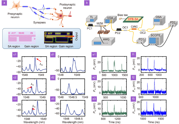
Yanan Han1, Shuiying Xiang1、*, Ziwei Song1, Shuang Gao1, Xingxing Guo1, Yahui Zhang1, Yuechun Shi2, Xiangfei Chen3, and Yue Hao1
Author Affiliations
  • 1State Key Laboratory of Integrated Service Networks, State Key Discipline Laboratory of Wide Bandgap Semiconductor Technology, Xidian University, Xi’an 710071, China
  • 2Yongjiang Laboratory, Ningbo 315202, China
  • 3Key Laboratory of Intelligent Optical Sensing and Manipulation, Ministry of Education, the National Laboratory of Solid State Microstructures, the College of Engineering and Applied Sciences, Institute of Optical Communication Engineering, Nanjing University, Nanjing 210023, China
  • show less
    DOI: 10.29026/oes.2023.230021 Cite this Article
    Yanan Han, Shuiying Xiang, Ziwei Song, Shuang Gao, Xingxing Guo, Yahui Zhang, Yuechun Shi, Xiangfei Chen, Yue Hao. Pattern recognition in multi-synaptic photonic spiking neural networks based on a DFB-SA chip[J]. Opto-Electronic Science, 2023, 2(9): 230021-1 Copy Citation Text show less
    (a) The geometry of multi-synaptic connections. (b) The experimental setup. The optical path is denoted by yellow, and the electrical path is black. The GDS file and chip micrograph of the DFB-SA neuron chip. (c1–c3) The optical spectrum of free-running DFB-SA, marked with different injection wavelengths. (d1–d3) The optical spectrum of DFB-SA with external optical injection corresponding to (c1–c3). (e1–e3) and (f1–f3) The input pattern and the corresponding output.
    Fig. 1. (a) The geometry of multi-synaptic connections. (b) The experimental setup. The optical path is denoted by yellow, and the electrical path is black. The GDS file and chip micrograph of the DFB-SA neuron chip. (c1c3) The optical spectrum of free-running DFB-SA, marked with different injection wavelengths. (d1–d3) The optical spectrum of DFB-SA with external optical injection corresponding to (c1–c3). (e1e3) and (f1f3) The input pattern and the corresponding output.
    The basic structure for supervised learning of photonic SNNs with temporal coding.
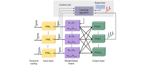
    Fig. 2. The basic structure for supervised learning of photonic SNNs with temporal coding.
    (a) The process of digit pattern recognition based on a multi-synaptic photonic spiking neural network. (b) The output classification. (c) The basic principle for temporal coding SNN. (d) The STDP rule. (e) The mean distance of 4 different training methods with different Nsyn.
    Fig. 3. (a) The process of digit pattern recognition based on a multi-synaptic photonic spiking neural network. (b) The output classification. (c) The basic principle for temporal coding SNN. (d) The STDP rule. (e) The mean distance of 4 different training methods with different Nsyn.
    The output spike timing of all 10 output neurons (the row) at the input of all 10 patterns (the column) when Nsyn=3.
    Fig. 4. The output spike timing of all 10 output neurons (the row) at the input of all 10 patterns (the column) when Nsyn=3.
    (a) The converged Distance with 1, 2, and 3 synapses, respectively. (b1–b2) Normalized weights for each of the two sets of synapses after convergence. (c1–c2) Normalized delays for each of the two sets of synapses after convergence. (d1) The converged Distance in the parameter space of weight mismatch and delay mismatch and (d2) projection of the contour with Distance=1.
    Fig. 5. (a) The converged Distance with 1, 2, and 3 synapses, respectively. (b1b2) Normalized weights for each of the two sets of synapses after convergence. (c1c2) Normalized delays for each of the two sets of synapses after convergence. (d1) The converged Distance in the parameter space of weight mismatch and delay mismatch and (d2) projection of the contour with Distance=1.
    (a1–j1) The input spike patterns for all the 10 output neurons. (a2–j2) The correlated outputs of DFB-SA. (k1) The output spike interval for all 10 output neurons of 20 experiment trials. (k2) The output spike power for all 10 output neurons of 20 experiment trials.
    Fig. 6. (a1j1) The input spike patterns for all the 10 output neurons. (a2j2) The correlated outputs of DFB-SA. (k1) The output spike interval for all 10 output neurons of 20 experiment trials. (k2) The output spike power for all 10 output neurons of 20 experiment trials.
    AlgorithmNetwork sizeNsyn=1Nsyn=2Nsyn=3
    Tempotron20×10(25.71±2.43)%(30.4±3.51)%(34.80±2.68)%
    ReSuMe20×10(19.4±2.19)%(27.75±5.56)%(29.60±4.10)%
    DL-ReSuMe20×10(37±7.78)%(42.80±1.30)%(47.20±2.39)%
    ANN-BP20×10(54.60±7.13)%(56.67±5.28)%(60.67±3.14)%
    CNN-BP(784×16)×10(79.4±1.52)%/
    Table 1. Accuracy of MNIST classification based on different models with different Nsyn.
    Yanan Han, Shuiying Xiang, Ziwei Song, Shuang Gao, Xingxing Guo, Yahui Zhang, Yuechun Shi, Xiangfei Chen, Yue Hao. Pattern recognition in multi-synaptic photonic spiking neural networks based on a DFB-SA chip[J]. Opto-Electronic Science, 2023, 2(9): 230021-1
    Download Citation