
Daixuan Wu, Jiawei Luo, Zhibing Lu, Hanpeng Liang, Yuecheng Shen, Zhaohui Li. Two-stage matrix-assisted glare suppression at a large scale[J]. Photonics Research, 2022, 10(12): 2693
- Photonics Research
- Vol. 10, Issue 12, 2693 (2022)
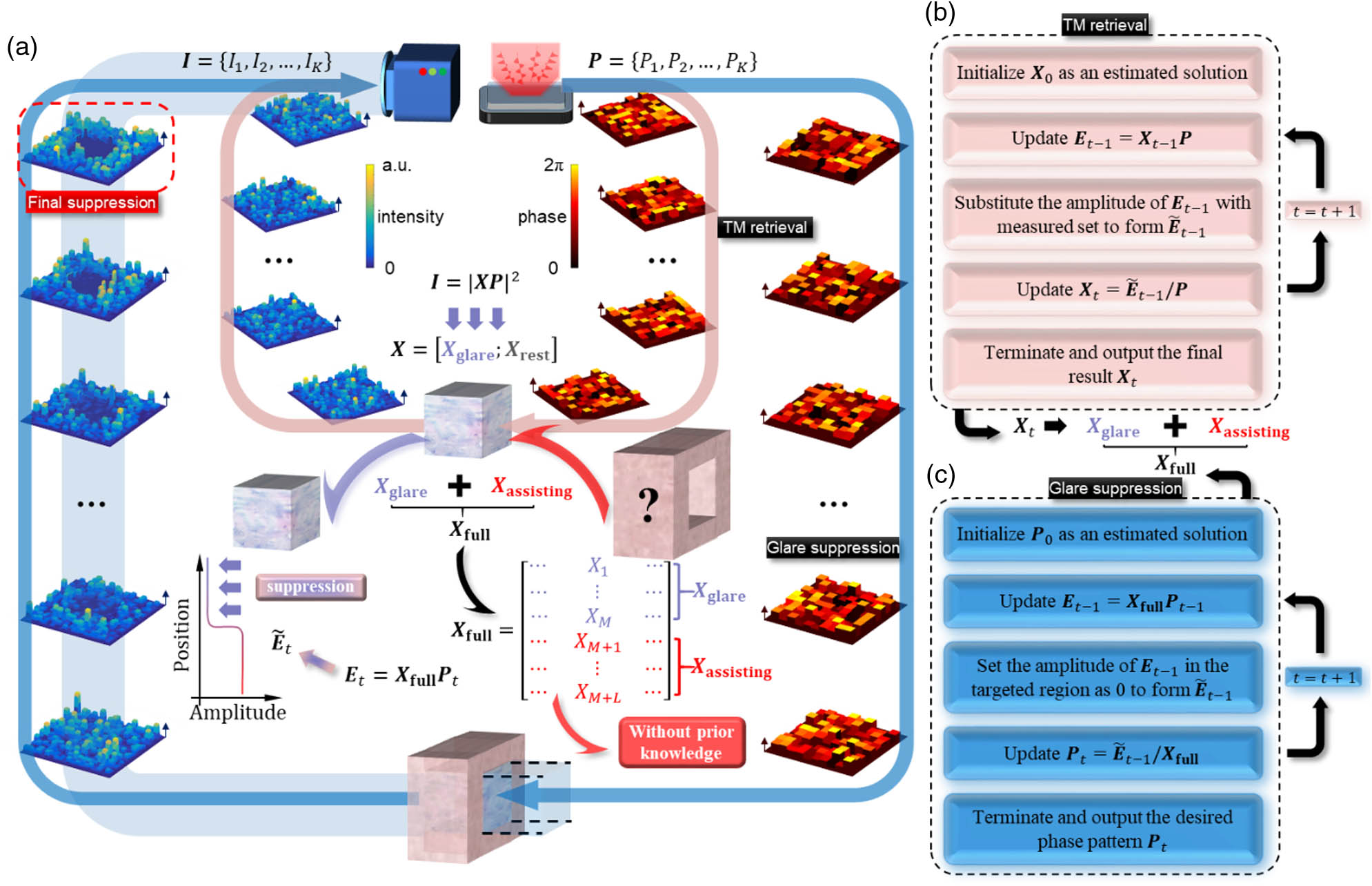
Fig. 1. Operational principle of the TAGS. (a) Schematic diagram of the operational principle, containing a pink inner loop of transmission matrix (TM) retrieval and a blue peripheral loop of glare suppression. (b) Flow chart of employing the generalized GS algorithm to retrieve the TM in the first stage. (c) Flow chart of employing the GS algorithm and the assisting matrix to synthesize the wavefront that suppresses glares in the second stage.
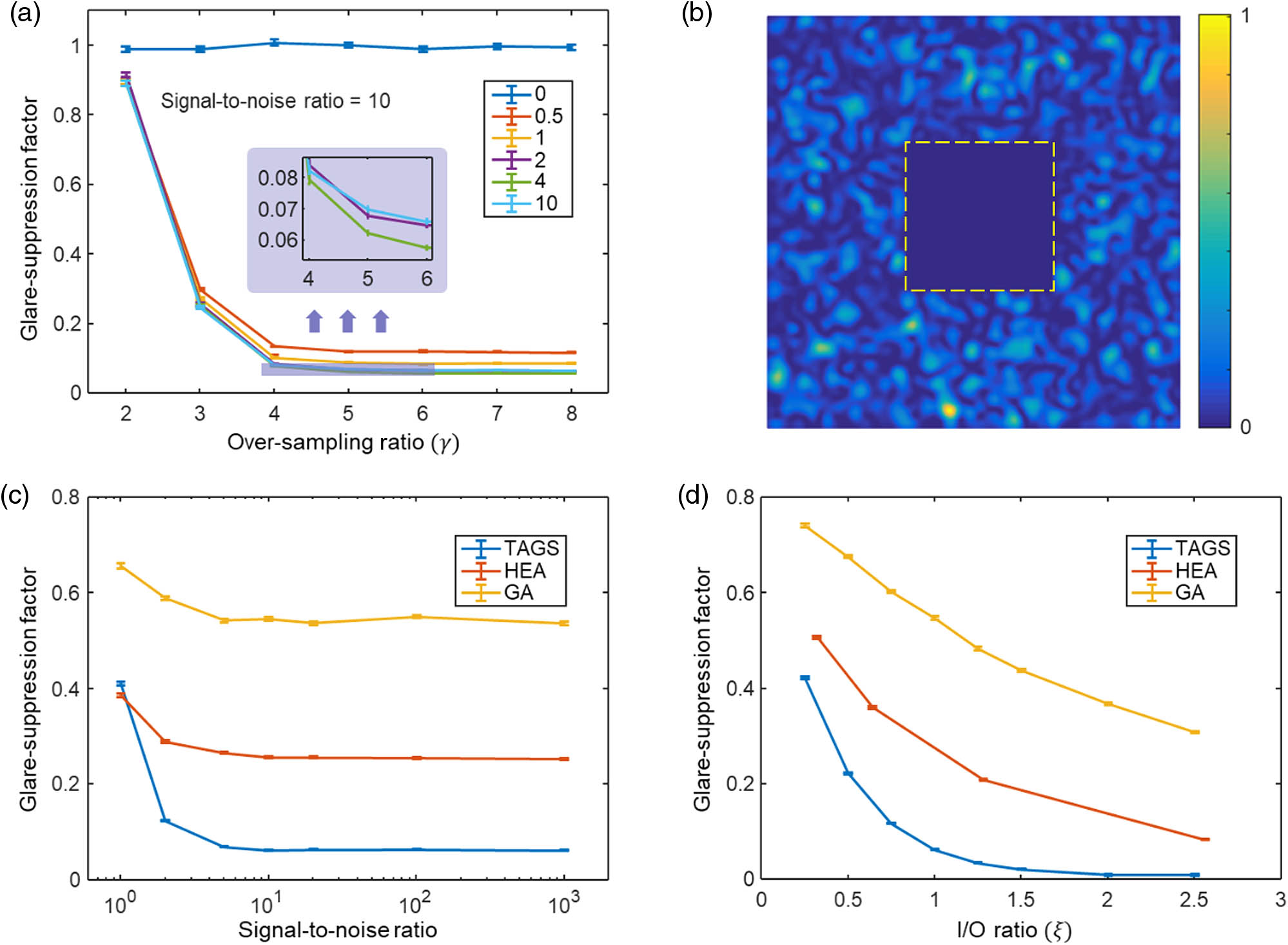
Fig. 2. Numerical results on examining the performance of the TAGS. (a) Glare-suppression factor as a function of the sampling ratio γ ζ γ = 5 ζ = 4 ξ = 1
Fig. 3. Experimental setup to perform the TAGS. HWP, half-wave plate; PBS, polarizing beam splitter; BB, beam block; L, lens; BS, beam splitter; SLM, spatial light modulator; M, mirror; P, polarizer; MMF, multimode fiber.
Fig. 4. Experimental results of the TAGS. (a) Camera-captured image when performing glare suppression by directly inverting the transmission matrix (TM). (b) Camera-captured image when performing the TAGS. A glare-suppression factor of about 0.11 was achieved for 100 speckles, which is enclosed in the yellow dashed box. (c) Examinations of employing the TAGS to suppress glares at larger scales. When fixing N = 100 N = 100 M = 100

Set citation alerts for the article
Please enter your email address
© Copyright 2018-2021 | Chinese Laser Press. All Rights Reserved 沪ICP备15018463号-20