Abstract
Scattering-induced glares hinder the detection of weak objects in various scenarios. Recent advances in wavefront shaping show one can not only enhance intensities through constructive interference but also suppress glares within a targeted region via destructive interference. However, due to the lack of a physical model and mathematical guidance, existing approaches have generally adopted a feedback-based scheme, which requires time-consuming hardware iteration. Moreover, glare suppression with up to tens of speckles was demonstrated by controlling thousands of independent elements. Here, we reported the development of a method named two-stage matrix-assisted glare suppression (TAGS), which is capable of suppressing glares at a large scale without triggering time-consuming hardware iteration. By using the TAGS, we experimentally darkened an area containing 100 speckles by controlling only 100 independent elements, achieving an average intensity of only 0.11 of the original value. It is also noticeable that the TAGS is computationally efficient, which only takes 0.35 s to retrieve the matrix and 0.11 s to synthesize the wavefront. With the same number of independent controls, further demonstrations on suppressing larger scales up to 256 speckles were also reported. We envision that the superior performance of the TAGS at a large scale can be beneficial to a variety of demanding imaging tasks under a scattering environment.1. INTRODUCTION
The role of optical scattering has been gradually attracting people’s attention in recent years. In a variety of applications, ranging from deep-tissue bio-imaging in medical diagnosis to foggy-night sensing in mundane life, handling optical scattering with special care is the key to a successful operation. In general, optical scattering causes two main challenges that hinder the successful imaging of objects under a scattering environment. The first challenge is wavefront distortion due to the inhomogeneity of scattering media, prohibiting direct imaging through optical scattering. For relatively thin scattering media, memory effects were exploited to reconstruct images through computational approaches [1–5]. For strong scattering, wavefront shaping and adaptive optics have been demonstrated with great success in addressing this challenge by correcting the scrambled information [6–13]. The successful operation of these techniques relies on the fact that, although being scrambled, the useful information is still carried by the distorted wavefront. The second challenge is the concealing of images due to the formation of laser speckles, i.e., glares. In this condition, the object we are looking at can be obscured by glares generated by a separate but strong illumination source. In contrast to the scenario encountered in the first challenge, the glares are originated from an ambient light source that neither interacts with the object nor carries any useful information. Therefore, one would expect to directly eliminate their affections, rather than correcting them for information retrieval. Since glares are commonly seen in a variety of practical scenarios, such as driving on a foggy night, and remain largely unaddressed, suppressing glares is of great value to many imaging applications under scattering environments.
Time-of-flight methods could potentially alleviate this issue by separating unwanted glares through time gating, but these methods usually inflict high demands on the temporal and spatial resolutions of imaging devices [14–16]. Glare suppression could also be realized through destructive interference and coherence gating, but delicate engineering work on the coherence function was required [17–19]. Inspired by wavefront shaping techniques that can enhance intensities within a certain area through constructive interference, Daniel et al. demonstrated the first active glare suppression using feedback-based wavefront shaping through destructive interference [20]. By controlling independent elements and employing the genetic algorithm (GA) [21], the authors experimentally darkened speckles to 17% of the original intensity values after 1000 iterations [20]. Further analysis of numerical simulation speculated that speckles could be effectively suppressed with independent controls. Later on, a Hadamard encoding algorithm (HEA) was proposed to improve the efficiency of the suppression process [22]. Experimentally, with independent controls, 1, 16, 36, and 64 speckles were effectively darkened to 0.04, 0.07, 0.17, 0.20 of the original intensity value, after 1200 intensity measurements [22]. It should be noted that using the wavefront shaping technique to actively suppress glares enjoys decent adaptability to almost all practical conditions, without the need for special instruments with high-demanding parameters. One can even directly visualize the desired object that was previously overwhelmed by glares without triggering data processing for reconstructing images. However, despite these accomplishments, the reported two methods were quite time-consuming due to the nature of the feedback scheme. Moreover, to guarantee satisfactory performances, the number of independent controls used during experiments was always orders of magnitude larger than the number of suppressed speckles. Due to the limited number of independent controls in practice, this inefficient condition also limits the number of speckles that can be suppressed. As a result, there is an urgent demand for developing new techniques to efficiently suppress glares.
The core principle of wavefront shaping is to synthesize the desired wavefront based on the knowledge of the transmission matrix (TM) of the scattering process. Among existing techniques, the feedback-based approach has the simplest implementation but has long been criticized for its inefficiency. Thus, to realize efficient glare suppression, it is natural to consider how to efficiently synthesize the desired wavefront once the knowledge of the TM is known. Intuitively, one would imagine such a wavefront can be synthesized either by multiplying the pseudoinverse of the TM with the desired output field, i.e., suppressed glares in the target area, or conjugating a portion of the elements in the TM [20]. However, it is difficult to implement such an intuitive idea with a phase-only spatial light modulator (SLM) in practice, as glare suppression requires accurate cancellation among different output modes. It has been numerically shown that this simple idea leads to a large residue of about 80% of the original intensity value [20]. Thus, how to synthesize the desired wavefront to suppress glares based on the knowledge of the TM is still unknown. In this work, we fill this blank by developing a method named two-stage matrix-assisted glare suppression (TAGS), which is capable of suppressing glares at a large scale. The proposed TAGS contains two major stages, i.e., TM retrieval and glare suppression, which exhibit several advantages in realizing efficient glare suppression by utilizing the framework of wavefront shaping. First, the entire procedure of the TAGS is purely non-holographic, which does not require an additional reference beam even for the stage of TM retrieval. Second, once the knowledge of TM is known, the wavefront, i.e., the phase map, that effectively suppresses the glares in the targeted area can be computationally synthesized in real-time, without the need for time-consuming hardware iteration. Third, effective glare suppression can be achieved even when the number of independent controls is equal to or less than the number of suppressed speckles . This property allows glare suppression at a large scale by using a limited number of independent controls. Fourth, active cancellation through destructive interference allows direct visualization of the object that was previously obscured by glares, without the need for further image processing. As a demonstration of the principle, we experimentally demonstrated suppressing glares at a large scale, which was generated by sending light through a multimode fiber (MMF). In particular, by employing only independent controls, we successfully suppressed 100 speckles to 0.12 of the original value and 256 speckles to 0.32 of the original value. The entire computational time cost to synthesize one desired phase map takes only 0.11 s. We anticipate that the development of the TAGS can open up a new avenue for suppressing glares under scattering environments, benefiting plenty of applications, such as astronomy, biophotonics, oceanography, and vehicle remote sensing.
Sign up for Photonics Research TOC. Get the latest issue of Photonics Research delivered right to you!Sign up now
2. OPERATIONAL PRINCIPLE OF THE TAGS
We start by describing the principle of the TAGS, which includes two stages: TM retrieval and glare suppression. A schematic diagram of the operational principle is also shown in Fig. 1. The first stage is to measure the TM of the scattering medium, which lays the foundation for the next stage of glare suppression. To be consistent, we adopt the generalized Gerchberg–Saxton (GS) algorithm [23] to retrieve the TM of the scattering medium non-holographically, which produces glares. It is worth noting that other algorithms that retrieve the TM [24–30] can be adopted as well. For completeness, the process of TM retrieval is illustrated as the pink inner loop in Fig. 1(a). By considering Rayleigh scattering, the TM is epitomized as to connect the input and output planes. Here, is the number of independent controls in the input plane, while is the number of speckles in the output modes. In practice, a liquid crystal based SLM is generally used to probe the scattering medium by sending a series of randomly distributed phase patterns . Having interacted with the scattering medium, the resulting speckle patterns are captured using a camera, which is denoted as . These captured speckle patterns contain the information of the TM, which can be mathematically described using matrix operations: . It is noteworthy that glare suppression is essentially energy redistribution, meaning the energy of the targeted speckles in the output plane needs to be transferred to other non-targeted speckles. In this condition, the retrieved TM may contain two parts and , while the prior one corresponds to the speckles that need to be suppressed. We will show in the following that the knowledge of is not necessary, and only the knowledge of is required for glare suppression. Thus, for simplicity without losing generality, with a dimension of is used in this stage. With the above notations, Fig. 1(b) shows the flow chart of employing the generalized GS algorithm to retrieve the TM of the scattering medium. Due to the nonlinearity induced by the square law inherent in intensity measurement, this process operates iteratively but converges quite efficiently. The TM retrieval starts with the initialization of the first estimation of TM . Then, and are calculated, where the subscript denotes the number of iterations and the operator “/” represents matrix division. The electric field is constructed by substituting the electric field with the measured amplitude, which borrows the concept of the GS algorithm [31]. To avoid converging to a local optimum, a power exponent of 2 to 1 is introduced to the measured amplitude [23]. The iteration process terminates if the correlation between and achieves more than 99.9999% or the number of iterations reaches 1000. This iteration process converges and produces a good estimation of the TM . Note that, due to the lack of a common referencing point, there always exists undetermined phase values among different rows of the TM [23–30]. Nonetheless, this issue does not trigger any problem in projecting intensity patterns through the scattering medium, as well as suppressing glares.
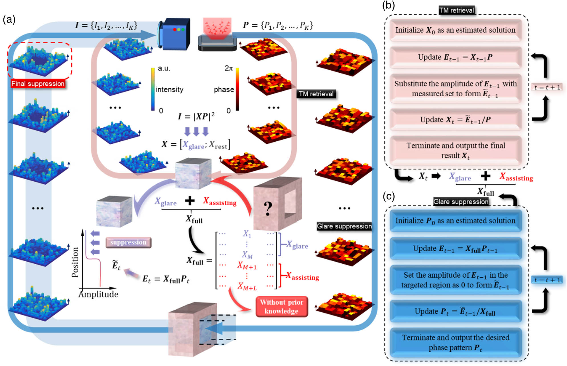
Figure 1.Operational principle of the TAGS. (a) Schematic diagram of the operational principle, containing a pink inner loop of transmission matrix (TM) retrieval and a blue peripheral loop of glare suppression. (b) Flow chart of employing the generalized GS algorithm to retrieve the TM in the first stage. (c) Flow chart of employing the GS algorithm and the assisting matrix to synthesize the wavefront that suppresses glares in the second stage.
Having estimated the TM in the first stage, we now proceed to describe the second stage. The primary task of this stage is to search for a proper wavefront that suppresses glares in the target region. Instead of using the pseudoinverse of the TM to determine the incident field, we adopted a GS algorithm to find the optimum incident field that has only phase variation to suppress glares in the targeted region. A similar idea has also been adopted to project the desired intensity patterns through an MMF by using a phase-only SLM [32]. In this condition, by setting the amplitude distribution of the incident plane to be flat and all amplitudes in the target region of the output plane to the demanding values, the GS algorithm forces the phase distribution in the incident plane to converge to the optimum value. However, simply zeroing out the target magnitude in the suppressed region is not enough, as the energy of these speckles needs to be redistributed elsewhere, indicating that TM in the non-suppressed region should be included. Interestingly, as we do not care about the intensity distribution outside the targeted region, the part of the TM that connects the incident plane and non-targeted region becomes unimportant. In other words, one can arbitrarily generate an assisting matrix with a dimension of and substitute . The assisting matrix is generated with each element drawn from a circular Gaussian distribution. The amplitude of these elements is then normalized to the same amplitude level of the elements in . Note that the generation of is completely random, which does not require any prior information about the true values of . Thus, the iteration process in the second stage utilizes a TM with a dimension of , which contains “correct” and “randomly generated” . This iteration process with the GS algorithm is illustrated as the blue peripheral loop in Fig. 1(a). With these descriptions, Fig. 1(c) shows the flow chart of employing the GS algorithm and the assisting matrix to synthesize the optimum wavefront that suppresses glares in the target region. The iteration process starts with an initial guess of the wavefront . Then, and are calculated. The electric field is formed by substituting the amplitude of within the targeted region to 0. Similar to the first stage, the iteration process terminates when the correlation between and achieves more than 99.9999% or the number of iterations reaches 1000. This iteration process finally converges and outputs the desired optimum phase map . The combination of the two stages that both utilize the GS algorithm forms the general procedure of the TAGS, which effectively realizes large-scale glare suppression.
3. NUMERICAL RESULTS ON EXAMINING THE PERFORMANCE OF THE TAGS
The performance of the TAGS is first investigated through numerical approaches. For the TAGS, certain parameters can affect its performance. In the first stage of TM retrieval, the number of phase maps determines the accuracy of the retrieved TM. Following the convention used in previous studies, a sampling ratio is defined as [7,23,33]. In the stage of glare suppression, the number of independent controls in the input plane over the number of suppressed speckles in the output plane also determines the effectiveness of glare suppression. We define another parameter named as an input-to-output (I/O) ratio. Previous studies generally adopted a large to suppress glares, i.e., at least 4 [20], causing difficulties in suppressing glares at a large scale. This choice may be partly inherited from the conventional recognition that wavefront shaping requires a large to form a bright optical focus. In the following, we will show that the TAGS can suppress glares at or even below, enabling controlling glares at a large scale. Another important parameter is the number of rows used for the assisting matrix. To account for this issue, we define an assisting ratio as the ratio between the number of rows in and the number of rows in .
We first examine how the choices of the sampling ratio and the assisting ratio affect the performance of the TAGS. As a proof of concept, the number of suppressed speckles is fixed to 100, which is quite large in comparison to previous studies [20,22]. The I/O ratio is set to 1. All the elements of the TM, regardless of and , are drawn from the same circular Gaussian distribution. Moreover, borrowing the concept of the peak-to-background ratio in wavefront shaping [9,34–38], a figure-of-merit parameter, which is defined as the glare-suppression factor, is employed to quantify the reduced intensities [19,22]. The glare-suppression factor is mathematically computed as the ratio between the averaged intensity within the targeted region and the averaged intensity before suppression. All of the following numerical results are executed through MATLAB (2020b) installed on a computer equipped with an i9-10900X 3.7 GHz computing processing unit and 16 GB random access memory. Figure 2(a) plots the numerically obtained glare-suppression factor as a function of the sampling ratio at seven representative points . Six different assisting ratios at are also investigated, exhibiting different lines in the figure. A signal-to-noise ratio (SNR) of 10 is set for intensity measurements during the stage of TM retrieval, which mimics the experimental condition. The introduction of the considerable noise level is important, as glare suppression is quite sensitive to noises. As we can see from the figure, hardly has any suppression effect, meaning that the existence of is essentially important to the performance of the TAGS. For other choices of , the suppression effects are similar but a bit different. By zooming in these lines, an inset reveals that leads to the best performance. Moreover, we also found that needs to be at least 4 to have substantial suppression effects. This observation is consistent with the previous study that, even without noise, we need to guarantee the accuracy of the retrieved TM [23]. Considering the practical conditions, and are chosen in the following of this work unless otherwise specified, in the consideration of being robust to the existence of noises. When , a glare-suppression factor down to approximately 0.06 can be achieved through TAGS. This result is remarkable, meaning that the TAGS can effectively suppress speckles on a large scale (100 speckles in this demo) with an averaged intensity down to 0.06 of the original value by controlling the same number of input modes through phase-only modulation. Figure 2(b) shows a typical result after performing the TAGS. The dashed yellow box indicates the two-dimensional targeted region, which contains 100 speckles.

Figure 2.Numerical results on examining the performance of the TAGS. (a) Glare-suppression factor as a function of the sampling ratio , under the various choices of the assisting ratio . (b) When , , and , a typical example after performing the TAGS. The suppressed 100 speckles are enclosed in the yellow dashed box. (c) Comparison of the robustness of different methods. The glare-suppression factors obtained by the TAGS, the Hadamard-encoding algorithm (HEA), and the genetic algorithm (GA) are plotted as a function of the signal-to-noise ratio. (d) Comparison of the efficiency of different methods. The glare-suppression factors obtained by the TAGS, the HEA, and the GA are plotted as a function of the input-output (I/O) ratio. Error bar, standard deviations of 100 independent trials.
We further compare the performance of the TAGS to existing methods based on feedback mechanisms, including the GA [20] and the HEA [22]. To compare the robustness of these methods at different noise levels, Fig. 2(c) plots the glare-suppression factor that can be obtained using these methods, when operating with various SNRs at . The I/O ratio is set to 1 for all three methods. As we can see from the figure, the TAGS significantly outperforms the other two feedback-based approaches in almost all cases. Moreover, we note that the TAGS still functions well with a glare-suppression factor of less than 0.1, when the SNR is down to 5. Recalling that the retrieved TM starts to lose accuracy when the SNR is within 10 [23], as reported in previous studies, we conclude the TAGS shows strong robustness in fighting against external disturbance. By setting the , we also investigate the performance of the TAGS with different choices of I/O ratio. Ideally, one would expect that the larger the I/O ratio is, the smaller the glare-suppression factor is. Figure 2(d) shows the achieved glare-suppression factor using three different methods under different . For the TAGS and the GA, the I/O ratio is set to . Since the HEA relies on Hadamard bases that scale with , the I/O ratio is set to . Here, we vary the number of independent controls while fixing the number of speckles to be suppressed at 100. Again, the TAGS outperforms the other two methods considerably. Even at , the TAGS can still achieve a quite small glare-suppression factor. In contrast, the GA and the HEA require much larger I/O ratios to obtain satisfactory suppression effects, as presented in previous works [20,22]. These results indicate that the TAGS has the potential to suppress large-scale glares with a limited number of independent controls, even at a low SNR level down to 5.
4. EXPERIMENTAL RESULTS OF THE TAGS
Having introduced the concept of the TAGS and numerically evaluated its performance, we now proceed to carry out experiments to validate its performance with practical implementations. A non-holographic system for glare suppression through the scattering medium is designed and demonstrated in Fig. 3. A 642 nm continuous-wave laser (MDL-C-642-30 mW, CNI) serves as the light source. The direction of the light was controlled by a pair of mirrors, while the intensity being dumped into the system was adjusted by a half-wave plate and a polarization beam splitter. The incident light was then expanded by a pair of lenses so that it can cover the active area of an SLM (PLUTO-2-NIR-011, Holoeye). The SLM generates a series of phase maps to probe the TM of the scattering medium. It is also responsible to produce the wavefront that suppresses glares. Subsequently, the modulated light was redirected into an objective lens through a beam splitter, which then interacted with the scattering medium to generate speckles. Any complex system or medium that produces glares can be used, including a pile of ground glass diffusers, MMFs, and even biological tissue. It should be noted that only a portion of the modulating area of the SLM can be coupled into the MMF through the objective lens. Having interacted with the complex system, the output speckles were captured using a camera (GS3-U3-32S4C, FLIR, , ). Both the SLM and the camera were controlled by the same computer used in the above numerical analysis. Before proceeding to glare suppression, we loaded a series of phase maps to the SLM and measured the output intensity values. The average value and the standard deviation of these measurements were estimated as 27.1 and 2.6, leading to an SNR of 10.
Figure 3.Experimental setup to perform the TAGS. HWP, half-wave plate; PBS, polarizing beam splitter; BB, beam block; L, lens; BS, beam splitter; SLM, spatial light modulator; M, mirror; P, polarizer; MMF, multimode fiber.
As a proof of concept, we chose to use an MMF (FC/PC-FC/PC-50/125-900 μm 1 m, Shenzhen Optics-Forest Inc.) in this work, which generates speckles at the distal end. Theoretically, this MMF supports propagating modes, where . Here, is the core diameter, is the numerical aperture (NA), and is the wavelength of light. Thus, about modes can be supported by this MMF along one polarization direction. However, since the objective lens we used has an NA of 0.15, the actual number of modes that can be coupled into this MMF is . As a result, we set the maximum number of independent controls to be 400 throughout this work. Moreover, to avoid considering vector modes, a pair of polarizers was used to ensure a single-polarization condition. Following the diagram in Fig. 1, the experimental procedure of the TAGS also consists of two stages. Guided by the numerical results, we chose , , and . The first stage is for TM retrieval. In this stage, a series of phase maps was randomly generated through the SLM, and each of them has independent phase values. Thus, we divided the effective area of SLM into partitions, and each partition holds an equal size of . The corresponding output was measured with the camera. In contrast to numerical investigations in which every element in the output plane corresponds to one speckle, the camera-measured intensity distribution encounters the sampling issue. By calculating the autocorrelation correlation function, it can be estimated that the coherence area, which is roughly the average size of one speckle, occupies about on the camera sensor. In other words, to suppress speckles in the output plane, one needs to consider and suppress on the camera sensor. Since the measured intensity pattern is the convolution between the output speckle field and the point spread function of the measurement system, the intensity of each pixel within the coherence area varies slightly. In other words, different compositions of neighboring speckles contribute to them. Thus, directly averaging all pixels within the coherence area causes inaccuracy when evaluating the intensity of one speckle grain. It is worth noting that this problem can be potentially mitigated by employing coherent detection. Nonetheless, in such a referenceless system, instead of using the averaged value of these , we pick only the value of the central pixel to represent the intensity of the speckle. Although such a choice may be more susceptible to measurement noises, it does generate a more accurate TM. In the second stage of glare suppression, we constructed with the retrieved TM. Before proceeding, we attempted to see what will happen by directly inverting the TM, i.e., sending in a wavefront of to the SLM. Here, denotes the desired optical field with the targeted region to be suppressed and the computes the phase value. As shown in Fig. 4(a), no observable suppression can be observed in the dashed yellow box, which encloses the targeted region. After executing the second stage of the TAGS, Fig. 4(b) shows a suppressed region in the dashed yellow box, exhibiting a glare-suppression factor of about 0.11. It is worth noting that, essentially, the prior image is simply the outcome of the first iteration of the latter one. Nonetheless, the comparison of these two images confirms the validity of the TAGS.
Figure 4.Experimental results of the TAGS. (a) Camera-captured image when performing glare suppression by directly inverting the transmission matrix (TM). (b) Camera-captured image when performing the TAGS. A glare-suppression factor of about 0.11 was achieved for 100 speckles, which is enclosed in the yellow dashed box. (c) Examinations of employing the TAGS to suppress glares at larger scales. When fixing , the achieved glare-suppression factor as a function of the number of suppressed speckles through the TAGS (blue) and direct matrix inversion (red). (d) Examinations on different partition strategies of the camera pixels. By fixing and , the achieved glare-suppression factor under different partition strategies through the TAGS (blue) and direct matrix inversion (red). Error bar, standard deviations of five independent realizations.
By fixing , we further investigated the capability of employing the TAGS to suppress glares at larger scales. Figure 4(c) shows the experimental results for various at . The achieved glare-suppression factor through the TAGS is illustrated in blue, exhibiting a slightly increasing trend as increases. The phenomenon is expected as suppressing more speckles generally requires controlling more independent controls. Nonetheless, these results indicate that effective glare suppression can still be realized even when the number of independent controls is fewer than that of the suppressed speckles. As a comparison, the glare-suppression factors obtained by directly inverting the TM, as noted above, are also provided in red, exhibiting a small but observable effect in suppressing glares (), which agrees with the observations in Ref. [20]. In previous demonstrations, physically correspond to one speckle, and this fact was employed to make partitions for the camera sensor. Interestingly, we found that it is not necessary to rigorously specify the partition of the camera sensor according to the physical size of speckles in practice. After fixing and (), we can take the liberty to subdivide the camera sensor with various choices on the partitions. For example, we stipulated , , and as new partition strategies, and only the intensity value of the central pixel is picked. It is worth noting that the number of suppressed speckles is still 100, and only the dimension of changes. Figure 4(d) shows the achieved glare-suppression factor for these different partition strategies. Notably, all partition strategies exhibit similar performance, albeit partitions with smaller pixel numbers tend to perform slightly better. Since partitions with smaller pixel numbers correspond to using more partitions to sample the speckle field, this observation can be intuitively understood as the reconstructed speckle field being more accurate with a higher sampling rate. This result indicates that the TAGS is not sensitive to the partition strategies, and one can freely choose a partition that is slightly smaller than the actual size of one speckle to guarantee near optimum operations. As a comparison, the glare-suppression factors obtained by directly inverting the TM are also provided in red for different partition strategies, showing unsatisfactory performance in glare suppression. For better visualization, suppressing results in Figs. 4(a) and 4(b) are marked with asterisks in Figs. 4(c) and 4(d).
We further attempted to achieve 400-speckle glare reduction utilizing an equal number of independent controls. When the speckle grain occupied on the camera sensor, we achieved nearly a full-screen glare suppression with . This experiment was repeated 5 times, and the output results were integrated as Visualization 1. We note that this number, i.e., 400 speckles, in the current study is limited by the number of effective modes that can be coupled into the MMF.
5. DISCUSSION AND CONCLUSION
The successful demonstration of the TAGS relies on the introduction of the assisting matrix . Although the dimension of this matrix seems not important in our numerical investigations, we found that a larger dimension of is beneficial to the convergence of the computation process in the TAGS. Since is randomly generated without any prior knowledge related to the actual situation, increasing the dimension of is only at the cost of computational resources. This property tremendously benefits the efficiency of the TAGS by avoiding measuring for a large TM that contains information outside the targeted region. Nonetheless, it should be noted that the computational processes in both stages are quite efficient. For example, to produce the image in Fig. 4(b) (suppress 100 speckles with 100 independent controls), the first stage took 0.35 s to computationally retrieve the TM, while the second stage took 0.11 s to computationally synthesize the optimum wavefront. Currently, the bottleneck on the operational time of the TAGS is the relatively slow refresh rate of the SLM and the framerate of the camera, which projects phase maps and measures the corresponding speckle patterns. In practice, it took 0.16 s to project one phase map and measure the output speckles. Thus, suppressing 100 speckles generally requires for the data acquisition process. We anticipate that, by employing fast devices with kilohertz response, the entire procedures of the TAGS can be reduced to within 1 s.
In conclusion, within the framework of wavefront shaping, we developed the TAGS to realize glare suppression at a large scale in a non-holographic system. In particular, we experimentally demonstrated an efficient large-scale glare suppression on hundreds of speckles by adopting an equal or smaller number of independent controls. These results make the TAGS a promising tool for the active cancellation of unwanted glares at a large scale, which benefits plenty of imaging applications. Because of its superior performances, we anticipate that the developed TAGS offers great prospects in suppressing glares in coherent optical imaging, as well as being heuristic to eliminate speckle background in ultrasound imaging.
References
[1] J. Bertolotti, E. G. van Putten, C. Blum, A. Lagendijk, W. L. Vos, A. P. Mosk. Non-invasive imaging through opaque scattering layers. Nature, 491, 232-234(2012).
[2] H. He, Y. Guan, J. Zhou. Image restoration through thin turbid layers by correlation with a known object. Opt. Express, 21, 12539-12545(2013).
[3] O. Katz, P. Heidmann, M. Fink, S. Gigan. Non-invasive single-shot imaging through scattering layers and around corners via speckle correlations. Nat. Photonics, 8, 784-790(2014).
[4] E. Edrei, G. Scarcelli. Memory-effect based deconvolution microscopy for super-resolution imaging through scattering media. Sci. Rep., 6, 33558(2016).
[5] M. Qiao, H. Liu, G. Pang, S. Han. Non-invasive three-dimension control of light between turbid layers using a surface quasi-point light source for precorrection. Sci. Rep., 7, 9792(2017).
[6] I. M. Vellekoop, A. P. Mosk. Focusing coherent light through opaque strongly scattering media. Opt. Lett., 32, 2309-2311(2007).
[7] S. Popoff, G. Lerosey, M. Fink, A. C. Boccara, S. Gigan. Image transmission through an opaque material. Nat. Commun., 1, 81(2010).
[8] X. Xu, H. Liu, L. V. Wang. Time-reversed ultrasonically encoded optical focusing into scattering media. Nat. Photonics, 5, 154-157(2011).
[9] Y. M. Wang, B. Judkewitz, C. A. DiMarzio, C. Yang. Deep-tissue focal fluorescence imaging with digitally time-reversed ultrasound-encoded light. Nat. Commun., 3, 928(2012).
[10] I. N. Papadopoulos, J.-S. Jouhanneau, J. F. A. Poulet, B. Judkewitz. Scattering compensation by focus scanning holographic aberration probing (F-SHARP). Nat. Photonics, 11, 116-123(2017).
[11] J.-H. Park, Z. Yu, K. Lee, P. Lai, Y. Park. Perspective: wavefront shaping techniques for controlling multiple light scattering in biological tissues: toward in vivo applications. APL Photon., 3, 100901(2018).
[12] P. Pai, J. Bosch, M. Kühmayer, S. Rotter, A. P. Mosk. Scattering invariant modes of light in complex media. Nat. Photonics, 15, 431-434(2021).
[13] H. Ruan, J. Xu, C. Yang. Optical information transmission through complex scattering media with optical-channel-based intensity streaming. Nat. Commun., 12, 2411(2021).
[14] K. M. Yoo, Q. Xing, R. R. Alfano. Imaging objects hidden in highly scattering media using femtosecond second-harmonic-generation cross-correlation time gating. Opt. Lett., 16, 1019-1021(1991).
[15] G. W. Faris, M. Banks. Unconverting time gate for imaging through highly scattering media. Opt. Lett., 19, 1813-1815(1994).
[16] M. Dahan, T. Laurence, F. Pinaud, D. S. Chemla, A. P. Alivisatos, M. Sauer, S. Weiss. Time-gated biological imaging by use of colloidal quantum dots. Opt. Lett., 26, 825-827(2001).
[17] I. Grulkowski, J. J. Liu, B. Potsaid, V. Jayaraman, J. Jiang, J. G. Fujimoto, A. E. Cable. High-precision, high-accuracy ultralong-range swept-source optical coherence tomography using vertical cavity surface emitting laser light source. Opt. Lett., 38, 673-675(2013).
[18] S. Woo, S. Kang, C. Yoon, H. Ko, W. Choi. Depth-selective imaging of macroscopic objects hidden behind a scattering layer using low-coherence and wide-field interferometry. Opt. Commun., 372, 210-214(2016).
[19] E. H. Zhou, A. Shibukawa, J. Brake, H. Ruan, C. Yang. Glare suppression by coherence gated negation. Optica, 3, 1107-1113(2016).
[20] A. Daniel, L. Liberman, Y. Silberberg. Wavefront shaping for glare reduction. Optica, 3, 1104-1106(2016).
[21] D. B. Conkey, A. N. Brown, A. M. Caravaca-Aguirre, R. Piestun. Genetic algorithm optimization for focusing through turbid media in noisy environments. Opt. Express, 20, 4840-4849(2012).
[22] J. Luo, Z. Wu, D. Wu, Z. Liu, X. Wei, Y. Shen, Z. Li. Efficient glare suppression with Hadamard-encoding-algorithm-based wavefront shaping. Opt. Lett., 44, 4067-4070(2019).
[23] G. Huang, D. Wu, J. Luo, L. Lu, F. Li, Y. Shen, Z. Li. Generalizing the Gerchberg–Saxton algorithm for retrieving complex optical transmission matrices. Photon. Res., 9, 34-42(2021).
[24] R. N. Mahalati, D. Askarov, J. P. Wilde, J. M. Kahn. Adaptive control of input field to achieve desired output intensity profile in multimode fiber with random mode coupling. Opt. Express, 20, 14321-14337(2012).
[25] A. Drémeau, A. Liutkus, D. Martina, O. Katz, C. Schülke, F. Krzakala, S. Gigan, L. Daudet. Reference-less measurement of the transmission matrix of a highly scattering material using a DMD and phase retrieval techniques. Opt. Express, 23, 11898-11911(2015).
[26] M. N’Gom, M.-B. Lien, N. M. Estakhri, T. B. Norris, E. Michielssen, R. R. Nadakuditi. Controlling light transmission through highly scattering media using semi-definite programming as a phase retrieval computation method. Sci. Rep., 7, 2518(2017).
[27] L. Deng, J. D. Yan, D. S. Elson, L. Su. Characterization of an imaging multimode optical fiber using a digital micro-mirror device based single-beam system. Opt. Express, 26, 18436-18447(2018).
[28] T. Zhao, L. Deng, W. Wang, D. S. Elson, L. Su. Bayes’ theorem-based binary algorithm for fast reference-less calibration of a multimode fiber. Opt. Express, 26, 20368-20378(2018).
[29] G. Huang, D. Wu, J. Luo, Y. Huang, Y. Shen. Retrieving the optical transmission matrix of a multimode fiber using the extended Kalman filter. Opt. Express, 28, 9487-9500(2020).
[30] Z. Wang, D. Wu, G. Huang, J. Luo, B. Ye, Z. Li, Y. Shen. Feedback-assisted transmission matrix measurement of a multimode fiber in a referenceless system. Opt. Lett., 46, 5542-5545(2021).
[31] R. W. Gerchberg. A practical algorithm for the determination of plane from image and diffraction pictures. Optik, 35, 237-246(1972).
[32] D. Loterie, S. Farahi, I. Papadopoulos, A. Goy, D. Psaltis, C. Moser. Digital confocal microscopy through a multimode fiber. Opt. Express, 23, 23845-23858(2015).
[33] S. Popoff, G. Lerosey, M. Fink, A. C. Boccara, S. Gigan. Controlling light through optical disordered media: transmission matrix approach. New J. Phys., 13, 123021(2011).
[34] R. Li, T. Peng, Y. Liang, Y. Yang, B. Yao, X. Yu, J. Min, M. Lei, S. Yan, C. Zhang, T. Ye. Interleaved segment correction achieves higher improvement factors in using genetic algorithm to optimize light focusing through scattering media. J. Opt., 19, 105602(2017).
[35] J. Xu, H. Ruan, Y. Liu, H. Zhou, C. Yang. Focusing light through scattering media by transmission matrix inversion. Opt. Express, 25, 27234-27246(2017).
[36] Y. Shen, Y. Liu, C. Ma, L. V. Wang. Sub-Nyquist sampling boosts targeted light transport through opaque scattering media. Optica, 4, 97-102(2017).
[37] C. Ma, J. Di, Y. Li, F. Xiao, J. Zhang, K. Liu, X. Bai, J. Zhao. Rotational scanning and multiple-spot focusing through a multimode fiber based on digital optical phase conjugation. Appl. Phys. Express, 11, 062501(2018).
[38] Y. Luo, S. Yan, H. Li, P. Lai, Y. Zheng. Towards smart optical focusing: deep learning-empowered dynamic wavefront shaping through nonstationary scattering media. Photon. Res., 9, B262-B278(2021).


