
Qingfeng Kong, Shuai Wang, Ping Yang, Haiqi Lin, Yong Liu, Bing Xu. Phase Diversity Wavefront Sensor Based on Secondary Image Compensation[J]. Laser & Optoelectronics Progress, 2020, 57(12): 121103
- Laser & Optoelectronics Progress
- Vol. 57, Issue 12, 121103 (2020)
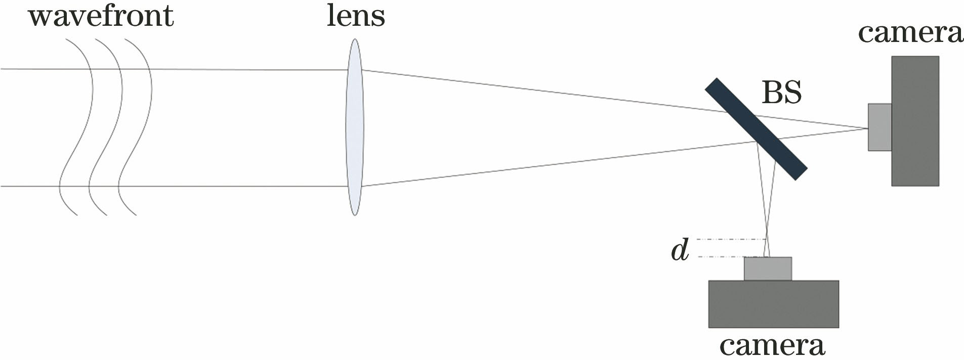
Fig. 1. Model of optical system
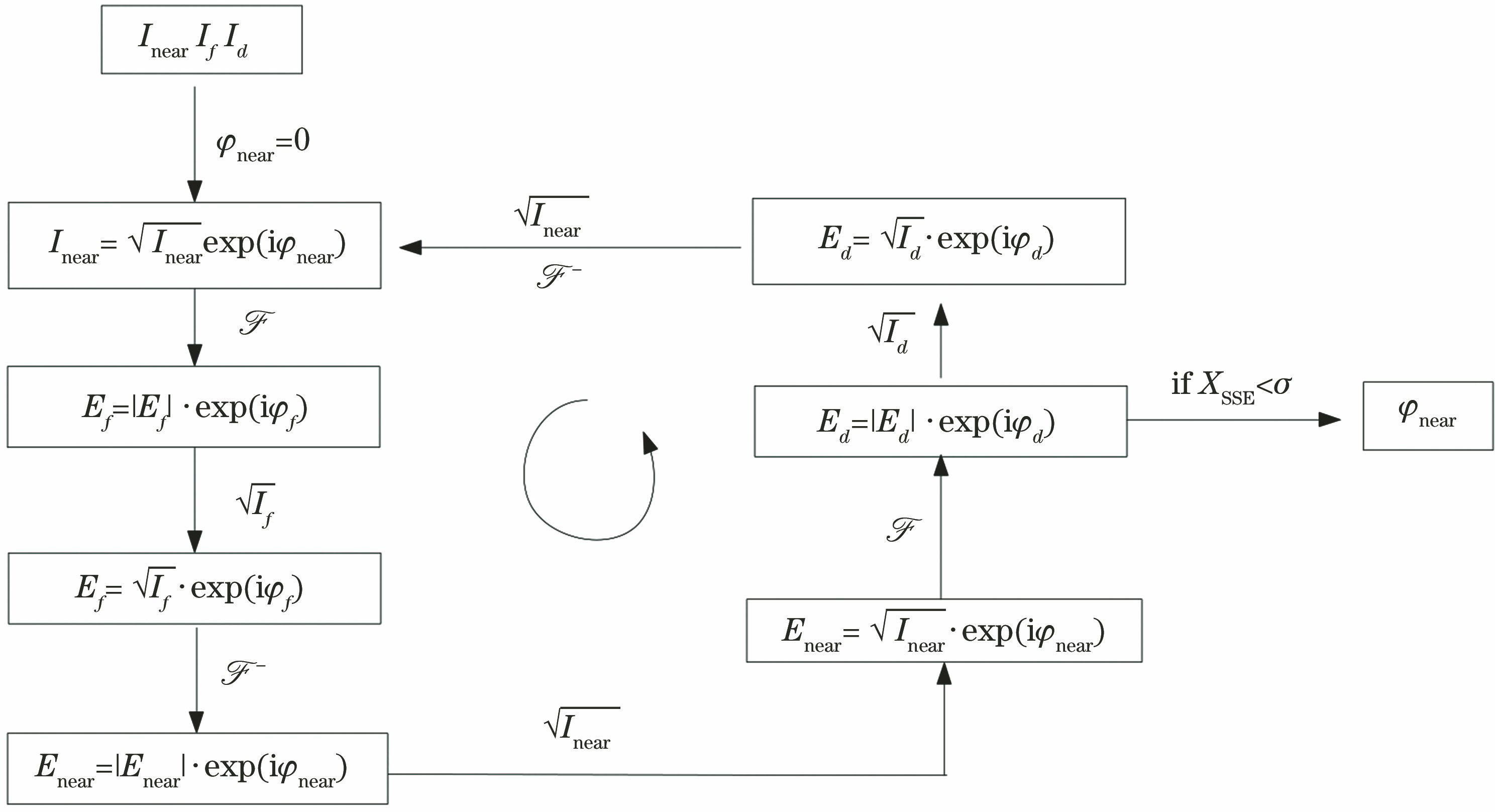
Fig. 2. Flow chart of PD algorithm
Fig. 3. Far-field images with aberration. (a) Image of the focal plane; (b) image of the defocused plane; (c) image of the saturated focal plane; (d) image of the saturated defocused plane; (e) fusion image of the focal plane; (f) fusion image of defocused plane
Fig. 4. Flow chart of AET-PDWFS
Fig. 5. Aberration distribution of incident wavefront
Fig. 6. Distribution of light intensity. (a) Focal plane image of PDWFS; (b) defocused plane image of PDWFS; (c) focal plane image of AET-PDWFS; (d) defocused plane image of AET-PDWFS
Fig. 7. Results of wavefront restoration. (a) Wavefront of PDWFS restored; (b) wavefront of AET-PDWFS restored; (c) wavefront residual of PDWFS restored; (d) wavefront residual of AET-PDWFS restored; (e) Zernike coefficient reconstructed by PDWFS; (f) Zernike coefficient reconstructed by AET-PDWFS
Fig. 8. Comparison of wavefront restoration accuracy of the two methods under different signal-to-noise ratios. (a) PV; (b) RMS
Fig. 9. Schematic diagram of the experimental device
Fig. 10. Images collected from experiment. (a) Regular image of the focal plane; (b) regular image of the defocused plane; (c) saturated image of the focal plane; (d) saturated image of the defocused plane
Fig. 11. Images of the AET-PDWFS fusion. (a) Image of the focal plane; (b) image of the defocused plane
Fig. 12. Aberration plate shape measured by MARK IV interferometer
Fig. 13. Results of wavefront reconstruction. (a) PDWFS; (b) AET-PDWFS

Set citation alerts for the article
Please enter your email address
© Copyright 2018-2021 | Chinese Laser Press. All Rights Reserved 沪ICP备15018463号-20