• Acta Optica Sinica
  • Vol. 43, Issue 7, 0726003 (2023)
Xiangyang Zhu1, Song Qiu1, You Ding1, Tong Liu1, Zhengliang Liu1, and Yuan Ren2、*
Author Affiliations
  • 1Department of Aerospace Science and Technology, Space Engineering University, Beijing 101416, China
  • 2Department of Basic Course, Space Engineering University, Beijing 101416, China
  • show less
    DOI: 10.3788/AOS221762 Cite this Article Set citation alerts
    Xiangyang Zhu, Song Qiu, You Ding, Tong Liu, Zhengliang Liu, Yuan Ren. Rotational Doppler Effect Analysis of Multi-Radial Index Laguerre-Gaussian Beam[J]. Acta Optica Sinica, 2023, 43(7): 0726003 Copy Citation Text show less
    Simulation results of number of radial zero points and intensity distribution of LG beam. (a) Relationship between the number of radial zero points of Laguerre function and the radial index p when topological charge is 15; (b) radial intensity of LG beam with radial index of 0-5 when the topological charge is 15
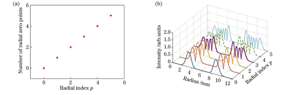
    Fig. 1. Simulation results of number of radial zero points and intensity distribution of LG beam. (a) Relationship between the number of radial zero points of Laguerre function and the radial index p when topological charge is 15; (b) radial intensity of LG beam with radial index of 0-5 when the topological charge is 15
    Schematic of relative position of LG beam and rotating object,O is the rotation center of the object,O1 is the center of the LG beam, and d is the distance between O and O1. (a) Schematic of relative position of LG beam and rotating object when d=0, i.e. O1 and O coincide; (b) schematic of relative position of LG beam and rotating object when the optical axis does not coincide with the rotating axis
    Fig. 2. Schematic of relative position of LG beam and rotating object,O is the rotation center of the object,O1 is the center of the LG beam, and d is the distance between O and O1. (a) Schematic of relative position of LG beam and rotating object when d=0, i.e. O1 and O coincide; (b) schematic of relative position of LG beam and rotating object when the optical axis does not coincide with the rotating axis
    Experiment setup and phase distribution diagrams. (a) Schematic of RDE experiment setup of LG beam with different radial indices; (b) phase distribution diagrams of LG beam with radial index from 0 to 5 when the topological charge is ±20
    Fig. 3. Experiment setup and phase distribution diagrams. (a) Schematic of RDE experiment setup of LG beam with different radial indices; (b) phase distribution diagrams of LG beam with radial index from 0 to 5 when the topological charge is ±20
    Experimental results. (a1)(a2) Intensity of LG beam with different radial indices; (b1)(b2) signal intensity of the reflected light in the time domain, dotted line indicates the mean of time domain signal intensity; (c1)(c2) rotational Doppler spectra in the frequency domain after transformation, dotted frame is the frequency domain signal broadening area, the straight solid line represents the average signal power value of the spectrum broadening range in the dotted frame, and the dot is the central frequency shift point
    Fig. 4. Experimental results. (a1)(a2) Intensity of LG beam with different radial indices; (b1)(b2) signal intensity of the reflected light in the time domain, dotted line indicates the mean of time domain signal intensity; (c1)(c2) rotational Doppler spectra in the frequency domain after transformation, dotted frame is the frequency domain signal broadening area, the straight solid line represents the average signal power value of the spectrum broadening range in the dotted frame, and the dot is the central frequency shift point
    Curves of measured rotational speed changed with radial index when the different radial index LG beam whose topological charge is ±20 is used as incident light and there is lateral misalignment between the center of rotating object and the center of LG beam
    Fig. 5. Curves of measured rotational speed changed with radial index when the different radial index LG beam whose topological charge is ±20 is used as incident light and there is lateral misalignment between the center of rotating object and the center of LG beam
    Average RDE signal amplitude varied with radial index under different topological charges when the rotating speed is 50 Hz
    Fig. 6. Average RDE signal amplitude varied with radial index under different topological charges when the rotating speed is 50 Hz
    Xiangyang Zhu, Song Qiu, You Ding, Tong Liu, Zhengliang Liu, Yuan Ren. Rotational Doppler Effect Analysis of Multi-Radial Index Laguerre-Gaussian Beam[J]. Acta Optica Sinica, 2023, 43(7): 0726003
    Download Citation