Fan Yang1, Mikhail Y. Shalaginov1, Hung-I Lin1, Sensong An1..., Anu Agarwal1, Hualiang Zhang2, Clara Rivero-Baleine3, Tian Gu1,4,* and Juejun Hu1,4,*|Show fewer author(s)
Fan Yang, Mikhail Y. Shalaginov, Hung-I Lin, Sensong An, Anu Agarwal, Hualiang Zhang, Clara Rivero-Baleine, Tian Gu, Juejun Hu, "Wide field-of-view metalens: a tutorial," Adv. Photon. 5, 033001 (2023)
Copy Citation Text
Wide field-of-view (FOV) optics are essential components in many optical systems, with applications spanning imaging, display, sensing, and beam steering. Conventional refractive wide FOV optics often involve multiple stacked lenses, resulting in large size and weight as well as high cost. Metasurface lenses or metalenses promise a viable solution to realizing wide FOV optics without complex lens assembly. We review the various architectures of wide FOV metalenses, elucidate their fundamental operating principles and design trade-offs, and quantitatively evaluate and contrast their imaging performances. Emerging applications enabled by wide FOV metasurface optics are also discussed.
Field of view (FOV) is an essential metric for gauging the performance of optical systems. In an imaging instrument, having a wide-FOV (WFOV) allows capturing the surrounding scene in a single frame without image stitching or mechanical scanning. Therefore, WFOV imaging optics are extensively applied in photography, microscopy, biomedical diagnosis, navigation and control, three-dimensional (3D) sensing, security surveillance, and beyond.1 Optical reciprocity stipulates that WFOV systems can also be used for light or image projection, a much sought-after feature enabling wide-angle beam steering and immersive displays for augmented/virtual reality (AR/VR) devices, automotive sensors, gaming simulators, and movie theaters.
Traditional WFOV optics used in these applications are based on refractive lenses. As the angle of incidence (AOI) of light with respect to optical axis increases, the angle-dependent monochromatic Seidel aberrations—coma, astigmatism, and field curvature—are exacerbated on top of on-axis spherical aberration. To suppress these aberrations, the conventional solution involves distributing the light-bending power over multiple refractive surfaces in stacked compound lenses, which, however, comes at the expense of system size, weight, cost, and complexity.
Optical metasurfaces, which comprise arrays of subwavelength structures (often termed “meta-atoms”),2–16 present an alternative approach to implement WFOV optical systems with significant size, weight, power, and cost (SWaP-C) advantages. In addition to mitigating spherical17–22 and chromatic aberrations,23–31 optics based on metasurface lenses (i.e., metalenses) have also been proven to effectively suppress the AOI-dependent Seidel aberrations, thereby facilitating WFOV operation.
Sign up for Advanced Photonics TOC. Get the latest issue of Advanced Photonics delivered right to you!Sign up now
Here, we take a deep dive into the field of WFOV metalenses, deliberating on their design approaches, underlying physics, performance characteristics, and potential applications. This article is organized as follows. We start by defining a set of standardized performance metrics for WFOV lenses to facilitate comparison between different architectures on an equal footing. Etendue conservation as a fundamental design constraint governing WFOV lenses will also be highlighted and quantified. Next, we review various metasurface architectures that have been pursued to expand the FOV of optical systems and quantitatively evaluate their performance. Analytical solutions for several designs will be formulated, providing a computationally efficient design approach in place of traditional numerical optimization based on polynomial expansion. We then proceed to discuss applications in consumer electronics, biomedicine, beam steering, immersive display,32 and defense, where WFOV meta-optics are likely going to make a significant impact. Finally, promising future research directions that can further enhance and expand the functionalities of WFOV meta-optical systems are presented.
2 Performance Metrics Characterizing WFOV Optics
2.1 Optical Performance Parameters
At the optical component level, the optical performance of a WFOV lens is measured by a set of classical parameters characterizing: (1) resolution, such as point spread function (PSF), modulation transfer function (MTF), or the Strehl ratio; (2) diffraction efficiency, defined as the fraction of optical power impinging on the lens aperture that contributes to the PSF;33 (3) stray background formally characterized by the veiling glare index (VGI)34 (since most literature on metalenses does not report VGI, the ratio of diffraction efficiency over bulk transmission efficiency of the optics provides a rough measure of glare); and (4) distortion.
While the performance measures may appear straightforward, care must be taken in their interpretation. First, we note that (angular) FOV, which is generally defined as the angular extent that an optical system can image, is a parameter pertinent to the entire optical system (e.g., the imaging sensor size) and therefore is not included in the list above. At the component level, the angle-dependent PSF, diffraction efficiency, and distortion provide full information to assess the angular performance of the optics alone. When the FOV figure is quoted to characterize a lens in literature, it is usually associated with the angular range where the optics resolution remains above a certain threshold, e.g., the diffraction limit (). This definition is by no means universal: for instance, it obviously does not apply to lenses whose performances are consistently below the diffraction limit. This ambiguity is removed with the introduction of the volumetric channel density (VCD) parameter (Sec. 2.2).
Second, we want to stress that full width at half-maximum (FWHM) of focal spot, which does not account for stray background or sidelobes, is not a proper measure of lens resolution, as correctly pointed out by other authors.33
Third, care must be taken in quantifying and interpreting optical efficiency figures of WFOV optics. The ambiguity is twofold. On the one hand, the canonical definition of diffraction efficiency can be challenging to implement in practical measurements or even in simulations for lenses with significant stray background. This is because the spatial extent of nonzero PSF can be difficult to determine due to background noise or overlap with specular (zeroth-order) transmission in experiments. Moreover, the concept of PSF associated with first-order diffraction ceases to be meaningful, even in modeling, if the stray background spans multiple diffraction orders. In this case, another parameter “focusing efficiency,” defined as the fraction of optical power encircled within a certain area around the focal spot over the total incident power, is often quoted as a less rigorous proxy.33 One should bear in mind that there is considerable ambiguity regarding the metric due to the different encircled areas quoted (sometimes with severe PSF truncation). On the other hand, WFOV optics is unique in that all WFOV lenses must restrict the entrance pupil (either via a physical or a virtual aperture stop) to conserve etendue (Sec. 2.3). When one quotes efficiency numbers, they are customarily normalized to optical power incident on the entire physical area of the first optic in a compound lens. As a result, the efficiency figures may be artificially suppressed; nonetheless, one should bear in mind that this is an artifact due to the presence of the aperture stop and should not be interpreted as poor optical quality of WFOV optics. In this regard, a better measure of the light-collection capability of WFOV lenses is the area of the physical aperture times the diffraction or focusing efficiency.
Last, but not least, distortion is an important metric only becoming significant in WFOV imaging systems. In WFOV systems, distortion is often inevitable, since distortion must be introduced during nonlinear mapping of the scene from a spherical angular space to a flat image plane. Unlike other third-order Seidel aberrations, distortion does not necessarily reduce the information in an image and can be computationally removed without losing image resolution, provided that it is not too large.35 However, when strong distortion is present, for example, near the edge of the field for most WFOV systems, the angular resolution along the meridional orientation can be compromised (Note S1 in the Supplemental Material). Therefore, specification of distortion, which in the case of an azimuthally symmetric optical system can be characterized by the dependence of image height (i.e., focal spot position) on the field angle, is important in gauging the imaging performance of WFOV optics.
2.2 Volumetric Channel Density
The basic parameters outlined above do not include nonoptical metrics such as size, even though size reduction of optical systems represents a major advantage of emerging optical technologies exemplified by metasurfaces. To account for both optical performance and compactness, a compound metric, VCD, was recently proposed by Ma et al.36 and is defined as where the total number of resolvable spots () is given by the area of the image divided by the average area of each spot,37 and the optical volume denotes the minimum volume that encloses all rays traveling through the system from the first surface to the final image. The 2/3 exponent ensures that the metric is scale-invariant for diffraction-limited systems, i.e., VCD becomes independent of system dimensions for the same aberration-free optical architecture. In an aberrated system, the Seidel aberrations increase with the aperture size,38 which would result in degradation of VCD with increasing system size. In addition, since the area of spots scales with , where is the free-space wavelength, the wavelength-normalized parameter can be used to compare optical systems working at different wavelengths.
The VCD parameter also provides a simple (as compared to full AOI-dependent PSF/MTF prescriptions) and quantitative metric to gauge the angle-dependent performance of imaging optics. For an imaging system equipped with a given optic, its VCD becomes a function of FOV, where the latter is defined by the image sensor size. An FOV larger than what the optic can properly handle inevitably results in blurring at the edges of the field and a drop of VCD. The VCD versus FOV curve, therefore, offers a direct visual representation of the angle-dependent imaging performance of the underlying optic.
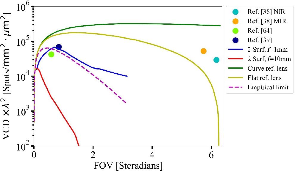
Figure 1 shows the versus FOV for ideal reference systems as well as several designs we discuss. The two ideal reference imagers illustrated in the insets both comprise a single thin lens with aberration-free performance across the entire FOV. A flat and a hemispherical image plane are assumed, respectively, for the two references. The purple dotted line corresponds to the empirical limit of conventional optics defined by Ma et al.36 The rapid drop of VCD above epitomizes the challenge associated with achieving WFOV in traditional optics, which mandates an increasing number of optical elements. The plot also highlights the advantage of metasurface optics, which furnish orders of magnitude improvement in VCD in the WFOV regime.
Figure 1.A VCD versus FOV plot comparing the VCD of several metalens designs (the blue and red solid lines correspond to optimized metalens doublets with 1-mm and 10-mm focal lengths, respectively), the empirical limit of conventional optics (purple dotted line), and those of ideal imaging systems following rectilinear projection (yellow and green solid lines assume a flat image sensor and a curved image sensor, respectively). Adapted from Ref. 36.
One limitation with the VCD metric is that it specifies monochromatic optical performance and disregards chromatic aberration. It also only applies to single-aperture systems, whereas multiaperture design provides a path to expanding FOV. We shall elaborate further on both aspects in the paper.
2.3 Etendue Conservation and Its Implications
Before we unveil different WFOV architectures, we would like to spotlight etendue conservation as one universal constraint that applies to all WFOV designs. The conservation law stipulates that for a WFOV imaging optic, the etendue at the image plane (or at an intermediate optical aperture) must be equal to (or greater than, when imperfect refraction or reflection takes place, e.g., with diffuse scattering) that at the entrance aperture. Given the large acceptance angle of a WFOV optic, etendue conservation essentially implies that the image is considerably larger than the entrance pupil. This is illustrated in the classical fisheye lens design example in Fig. 2. It shows that for all incident angles, only a small fraction of light rays arriving at the first optic are collected by the imaging array. In other words, the presence of an aperture stop far smaller than the physical size of the lenses is a common trait of WFOV optics.
Figure 2.An exemplary classical fisheye lens design (Nikkor 6 mm Fisheye), illustrating that the entrance pupil is much smaller in size than the lenses. Image courtesy of Shimizu.39
To quantify the impact of etendue conservation, Fig. 3 plots the size (diameter) ratio between the image and the entrance pupil as a function of FOV for different effective numerical aperture (NA) values. The curves assume etendue conservation, and therefore practical designs can only situate in regions on or above the curve with the corresponding effective NA. These curves allow a designer to immediately determine the required image sensor dimensions to capture a full FOV image based on entrance pupil size and target -number without detailed knowledge of the optical design. In addition, the figure suggests that large NA contributes to reducing the image and hence overall system size, although increasing NA beyond a certain point compromises the image quality (Sec. 3). In the same plot, data points corresponding to three experimentally validated metalens designs are also added. Two of the three designs strictly follow etendue conservation as expected and are characterized by near diffraction-limited imaging quality spanning the entire FOV. Interestingly, the design by Martins et al.41 appears to violate the etendue conservation principle; however, this is because the image size quoted in the figure is calculated based on the nominal focal spot position, which discounts a large amount of stray background light spreading across the image plane well outside the nominal image area. We revisit this topic in Sec. 3.2.
Figure 3.The curves plot size ratio between the image and the entrance pupil versus FOV for lenses with varying NAs calculated based on etendue conservation. The points correspond to experimentally validated designs from Ref. 40 (), 41 (), and 42 ().
In summary, well-designed WFOV optics, whether classical or meta-optical, preserve etendue. Consequently, WFOV optics are characterized by an entrance pupil size smaller than the cross-sectional area of the optical system. This characteristic can have a major impact on the nominal optical efficiencies of WFOV systems, as we alluded to in Sec. 2.1.
3 Optical Metasurfaces: All Roads that Lead to WFOV Optics
The canonical metalens design assumes a hyperbolic phase profile to convert an incident plane wave to a spherical wavefront. The phase profile is given as20where and are the coordinates of meta-atoms, and is the metalens focal length. The design eliminates spherical aberration at normal incidence. When a beam arrives at a metasurface at an oblique incidence angle , the desired phase distribution becomes where and are the coordinates of the focal spot on the image plane. The difference between the two phase profiles is responsible for other third-order (Seidel) aberrations, including coma, astigmatism, and field curvature, all of which are dependent on the AOI. In this section, we survey the various design strategies to mitigate these aberrations and thereby expand the FOV of metalenses. We also provide a representative selection of each of the WFOV metalens architectures and summarize the comparison between them in Tables 1 and 2, respectively. While our focus is on metalenses, the design principles discussed herein are equally applicable to other flat lens technologies, such as diffractive optical elements (DOEs).
Design type
FOV (deg)
Focusing efficiency (%)
Effective NA
Physical aperture size (mm)
Wavelength (nm)
[]
Singlet with an aperture stop40
>170
32 to 45
0.24
1
5200
Quadratic phase singlet41
>170
3.5
0.27
2
532
—
Metalens doublet43
50
50
0.44
0.31
532
Metalens doublet42
60
70
0.49
0.8
850
Metalens with angular phase control44
16
71
0.12
50λ
to
Table 1. A representative selection of WFOV metalens demonstrations: numbers only theoretically predicted without experimental validation are marked in boldfaced.
A simple architecture to increase the FOV of a flat lens involves placing an aperture stop in front of a flat metasurface (or DOE), as shown in Fig. 4(a). Light entering the aperture is spatially dispersed depending on the AOI, and as a result beams incident at different angles interact with different (yet continuous) portions of the metasurface. The rays are then focused onto a flat image plane in a (near-)telecentric configuration, whose significance will be revealed in our subsequent analysis. This scheme therefore allows angle-dependent engineering of the metasurface phase profile to suppress aberrations.
Figure 4.(a) A WFOV lens comprising an aperture stop in front of a single-layer metasurface: the different colors label light rays incident from varying AOIs. Image courtesy of Shalaginov et al.40 (b) Cross-sectional schematic of the metalens illustrating the different variables used in the analytical model.
Dating back to the early 19th century,45 the baseline design of an aperture coupled with a refractive lens was known to the photographic instrumentation community as a “landscape lens.” Its DOE-based flat optics embodiment was explored in the 1980s by Bobrov and Greishkh46,47 and Buralli and Morris.48 Based on the architecture, Grulois et al.49 fabricated a low-profile infrared (IR) camera, where a multiple-order DOE lens was used to imprint the optical phase profile to extend the spectral bandwidth. The metasurface counterparts of the landscape lens were theoretically investigated by Kalvach and Szabó50 and later experimentally implemented by Engelberg et al.,51 who further successfully deployed the lens to capture an outdoor image under filtered natural illumination. In these embodiments, the aperture and the DOE/metasurface are separated by an air gap, which restricts the attainable FOV due to rapid divergence of the DOE/metasurface size at large AOIs.
This limitation can be overcome by replacing the air gap with a solid substrate. Shalaginov et al.40,52 applied this approach to significantly expand the FOV of metalenses, demonstrating a flat fisheye lens with record -deg diffraction-limited FOV based on Huygens’ surface in the mid-IR53,54 (Fig. 5). Subsequently, the design was adapted to the near-IR wavelength of 940 nm by Zhang et al.,55 and designs targeting single,56 multiple,57 and even continuous broadband58 wavelength operation were also proposed and numerically modeled.
Figure 5.A flat fisheye metalens with -deg diffraction-limited FOV operating at wavelength. (a) Schematic of experimental setup for imaging a focal spot produced by the metalens at various AOIs. Examples of focal spot intensity images at (b) 0 deg, (c) 10 deg, (d) 30 deg, (e) 50 deg, (f) 70 deg, and (g) 85 deg. (h) Diffraction-limited focusing capability was concluded from the Strehl ratio values consistently above 0.8 threshold. Inset: Measured focal spot cross sections at 0 deg, 70 deg, and 85 deg AOIs (solid red lines); dotted black lines give theoretical results for aberration-free lens with the same -number. (i) Metalens focusing efficiency was measured to be at all AOIs. (j) Schematic of imaging setup. (k) Projected images of the 1951 USAF resolution test target with a period of . Images courtesy of Shalaginov et al.40
Design of the single-layer WFOV flat lens incorporating an aperture stop can be performed following an analytical formalism,59 which also provides critical insights into working principles and design trade-offs of this architecture. The theory presents a closed-form expression of the phase function for the WFOV lens: where , , , , and denote the radial position from the lens center, free-space wavelength, substrate refractive index, substrate thickness, and effective focal length, respectively [Fig. 4(b)]. is the image height (i.e., focal spot position on the image plane from the optical axis) at (in air, which relates to the AOI in the substrate via ) and it can be given in a differential form,
We have validated that the equations can precisely reproduce the aforementioned designs (for all literature examples whose detailed design prescriptions are available). Equation (5) can be approximated with a simple quadratic phase function, albeit only for coincidental parameter combinations,59 which explains why quadratic phase profiles have been successfully adopted in selected designs.51 In more general cases, Eq. (5) represents the optimal solution for suppression of spherical and comatic aberrations.
The ideal stigmatic focusing condition used to obtain Eq. (5) is only rigorously satisfied in the limit of infinitesimal aperture size. The theory further derives the root-mean-square wavefront error across an aperture of finite size as a measure of optical aberration to be59
This important expression explicitly relates lens performance to design parameters, including focal length , aperture size , substrate thickness , and refractive index of substrate . The parameter given by Eq. (5) also implicitly depends on the design parameters, and therefore quantitative design optimization necessitates a numerical solution of the two combined equations. That said, a few general trends can be inferred from the equations, showing that the imaging quality improves with increasing -number () or smaller NA, reducing aperture size, and minimizing the factor . This is intuitive, since larger aperture size leads to more spatial overlap of the pencils of rays with different AOIs, which tends to degrade the focusing performance. These design trade-offs have been quantitatively evaluated by Yang et al.59 The last condition, , corresponds to the image-space telecentric configuration, and thus Eq. (6) explains why all designs of this type in the literature40,51,52,55–58 assume approximate telecentricity. The near-telecentric configuration implies that these WFOV lenses exhibit barrel distortion at large AOIs, which is evident from the experimental images presented in Fig. 5(k) at . The distortion does not adversely impact the focal spot quality [Figs. 5(f) and 5(g)] and can be computationally removed in postprocessing. However, it compromises the meridional resolution at large field angles60—a common issue encountered by WFOV lenses.
3.2 Singlet Metalenses with a Quadratic Phase Profile
It is well known that the classical hyperbolic phase profile eliminates on-axis spherical aberration but suffers from severe off-axis coma aberration.61,62 This sensitivity to off-axis aberration can be alleviated by resorting to a phase distribution that is invariant with respect to incident angle change. A quadratic phase function assuming the following form fulfills this requirement, where , , and represent the radial position from the lens center, free-space wavelength, and effective focal length, respectively. Equation (7) assumes that the lens is designed for focusing in free space or air. For an obliquely incident beam at within the plane (where denotes the optical axis), a linear phase gradient term is added, yielding the following phase distribution after it exits the metasurface:
Equation (8) indicates that the phase profile can be regarded as the same parabolic function as Eq. (7) (neglecting the constant phase term) but laterally shifted along the axis for a distance of . Therefore, focusing properties are preserved for obliquely incident beams.
The quadratic phase concept was first proposed by Pu et al.63 and later on also numerically investigated by other authors.64–67 Martins et al. experimentally implemented the quadratic phase design to realize a WFOV metalens at 532 nm wavelength based on a Si-on-sapphire platform. Figure 6 presents the measured imaging performance comparison between the quadratic lens and a lens with the classical hyperbolic phase, clearly highlighting the enhanced wide-field imaging capability of the former. Distortion, which is obvious at the edge of the field in Fig. 6(a), is discussed in more details in Note S1 of the Supplemental Material. The same group further demonstrated a dual-function metalens via polarization multiplexing, which acts as a quadratic lens with expanded FOV and a hyperbolic lens with vanishing on-axis spherical aberration, respectively, for two orthogonal linear polarizations.68
Figure 6.Images taken with (a) a singlet lens with quadratic phase and (b) a singlet lens with hyperbolic phase. (c) Picture of the USAF resolution chart used in the experiment with the corresponding FOVs highlighted by the circles. (d) Measured transmission (dotted lines) and focusing efficiencies (dashed and solid lines) versus AOI for both polarizations. The focusing efficiency is normalized with respect to both total incident power on the entire metasurface (solid lines) and the transmission power (dashed lines). The focusing efficiencies were evaluated by integration of energy in the focal spot using a circular aperture with a radius of (which equals ). Images courtesy of Martins et al.41
One important characteristic of the quadratic phase lens is the existence of a virtual aperture. This can be understood by noticing that the phase gradient of a quadratic function [Eq. (7)] increases linearly with . At , is greater than or the free-space wavenumber, and therefore waves exiting the metasurface become evanescent. In other words, the incident light will either be reflected or trapped in the substrate by total internal reflection. For an obliquely incident beam, a virtual aperture with the same radius is similarly present with its center shifted to . The presence of virtual apertures reduces the nominal transmission efficiency of a quadratic lens when normalized against incident power over the entire metasurface area (which can be up to 4 times larger than the virtual aperture area), although this by no means represents an inherent limitation to the light collection power of the metalens, as discussed in Sec. 2.1. The large phase gradient at the outer region of a quadratic lens also constrains the practically attainable FOV due to phase discretization effect as pointed out by Lassalle et al.60
Despite its conceptual simplicity and elegance, one drawback of the quadratic singlet design is that it incurs large spherical aberration, resulting in significant stray background as well as low focusing efficiency. To quantitatively assess the impact of spherical aberration, we numerically investigated the performance of a metalens with a quadratic phase profile defined by Eq. (7), where and . The metasurface diameter needed to cover full 180-deg FOV is given by , and the virtual aperture has a diameter of . The optical performance of the lens is evaluated using the Kirchhoff diffraction integral, assuming that each meta-atom acts as an ideal point source of secondary wavelets with zero phase error and 100% transmission efficiency, which leads to complete light transmission within the virtual aperture and zero transmittance everywhere else. More details regarding the modeling approach can be found elsewhere.58
Figure 7(a) shows the simulated optical intensity distribution on the optical axis. Unlike a hyperbolic phase lens, which produces a single intensity peak localized on the focal plane, Fig. 7(a) shows an oscillatory intensity profile because of the spherical aberration. We also note that the peak intensity point does not locate on the nominal focal plane but rather is shifted to . We further plot the transverse focal spot profile in Fig. 7(b), showing an FWHM of , equivalent to that of an aberration-free lens with . We note that this FWHM value is slightly smaller than the experimental measurement result,41 likely because the transmittance of meta-atoms, especially the ones farther away from the virtual aperture center , is considerably lower than unity. The focusing efficiency , defined as the encircled power within a diameter of (i.e., 5 times FWHM) normalized to the power incident within the virtual aperture (which also equals the total transmitted power based on the 100% transmittance assumption) is 7.4%, which implies that the vast majority of transmitted light (92.6%) goes to the stray background. In comparison, a singlet with a physical aperture stop designed to achieve the same light-collection power, focal length, and focal spot FWHM claims a focusing efficiency and hence 44-fold improvement in signal-to-background ratio (refer to Note S2 in the Supplemental Material for more details). This shortcoming of the quadratic phase singlet can be mitigated by incorporating a second metasurface layer to correct spherical aberration, as discussed in the following section. It should be noted that in reality, meta-atoms reveal angular dependence, and therefore focusing efficiency further drops as the beam angle increases. This phenomenon becomes more significant in WFOV metalenses with large bending angles. A few techniques have been proposed to deal with the angular response of meta-atoms, including the grating averaging technique69 and the inverse freeform design.70
Figure 7.Simulated intensity distributions of a quadratic phase singlet metalens (black colored) and a singlet metalens with a physical aperture stop (rosewood colored): (a) along the optical axis and (b) on the transverse planes corresponding to peak on-axis intensity. The plane coincides with the metasurface, and the intensity values are normalized to the peak intensity.
Additional design degrees of freedom can be introduced by adding a second metasurface or DOE to the single-layer designs discussed above to form doublet flat lenses. The doublet configuration is schematically shown in Fig. 8(a), which consists of two layers of cascaded metasurfaces. To understand its working principle, an intuitive explanation has been formulated, which we are paraphrasing here.61,72 In this design, the bottom metasurface carries the main focusing power, and the top metasurface functions as a phase corrector analogous to a Schmidt plate in classical refractive optics [Fig. 8(b)], designed to have a phase distribution that neutralizes the spherical aberration of the bottom lens at normal incidence. Following an intuitive and insightful theoretical treatment introduced by Martins et al.,72 the bottom metasurface assumes a quadratic phase profile given by Eq. (7) [blue solid line in Fig. 9(a)]. To correct the on-axis spherical aberration, the top metasurface (marked as green rectangles in Fig. 9) must carry a phase profile [green dotted line in Fig. 9(a)] that compensates for the difference between the quadratic phase and the aberration-free hyperbolic phase [Eq. (2), orange solid line in Fig. 9(a)]. Provided that the spatial gradient of the top metasurface phase function is small, the phase profile remains almost unchanged after propagating through the substrate. Therefore, it is simply vertically displaced and superimposed onto the bottom metasurface phase, as shown in Fig. 9(a).
Figure 8.Schematic doublet lens designs for expanding the FOV. (a) Metalens doublet containing two metasurface layers on two sides of a substrate. (b) A classical doublet analog comprising a Schmidt plate for phase correction and a focusing lens. Images courtesy of Groever et al.43 and Huang et al.71
At oblique incidence, two changes to the optical phase distribution are introduced compared with the normal incidence case. First, the obliquely incident beam carries an additional in-plane linear phase gradient, which, combined with the quadratic phase [Eq. (7)], yields a laterally displaced quadratic phase profile [Eq. (8), blue solid line in Fig. 9(b)]. The top metasurface phase is also projected to a laterally shifted, off-center position as shown in Fig. 9(b). A laterally offset hyperbolic phase distribution [orange solid line in Fig. 9(b)] can be recovered when the lateral displacements of the bottom metasurface quadratic phase and the top metasurface correcting phase are aligned, thus producing a sharp focal spot in a telecentric configuration.
The superior wide-field performance of the doublet lens compared with a singlet following the classical hyperbolic phase profile is evident from Fig. 10, which compares their monochromatic imaging characteristics. While the two designs both generate aberration-free, sharp images at normal incidence, only the doublet effectively mitigates blurring due to coma aberration in off-axis imaging. In addition to single-wavelength operation, achromatic doublet metalenses have been proposed by coupling the design with meta-atom dispersion engineering.71,73,74 The doublet architecture has also been theorized to offer subdiffraction focusing with expanded FOV.75 Beyond doublets, triplet metalenses have also been demonstrated to suppress both monochromatic and chromatic aberrations.76
Figure 10.Imaging performance comparison between a doublet metalens and a singlet metalens with the classical hyperbolic phase profile. (a), (b) Images taken with (a) the doublet and (b) the singlet lenses. (c), (d) Measured MTFs of (c) the doublet and (d) the singlet lenses. Images courtesy of Arbabi et al.42
3.4 Angular Phase Control in Nonlocal Metasurfaces
The WFOV design approaches discussed so far are based on ray optics and have not actively exploited the potential to tailor an angle-dependent optical phase profile—a capability unique to nonlocal metasurfaces.77 The basic principle of angular phase control is to engineer the metasurface’s phase distribution such that its dependence on spatial coordinates and AOI fulfills Eq. (3). This can be accomplished by topology optimization (TO), which explores the tremendous number of design variables available in a complex, deep subwavelength metamaterial structure via gradient-based optimization.78–82 The technique has already been extensively applied to designing freeform metasurfaces83–88 as well as other nanophotonic structures with nonintuitive geometries.89–94
Figure 11(a) shows the cross-sectional layout of a cylindrical, monochromatic metalens comprising five layers of Si patterns designed using TO.95 The optical phase profile of the lens is dependent on the AOI, as shown in Fig. 11(d), and the phase profiles agree well with the ideal phase functions required for aberration-free focusing at the AOIs. Modeled focal spot profiles in Figs. 11(b) and 11(c) indicate that the lens can indeed achieve sharp focusing at the four AOIs as designed. In addition to optimizing for monochromatic focusing at discrete AOI values, the TO-based design can also support achromatic operation over a continuous angular range. As an example, an lens of in diameter and in thickness can cover 23% spectral bandwidth over a 16-deg FOV.44
Figure 11.A metalens designed with angular phase control. (a) The lens consists of five layers of silicon (black) embedded in an matrix (gray). (b) Finite-difference time-domain analysis of the far-field optical intensity distribution at four AOIs. (c) The modeled field intensities (circles) on the focal plane, which closely follow the ideal diffraction limit (solid lines). (d) AOI-dependent phase profile of the lens (red circles) overlaid with the ideal aberration-free phase profile (black line). Images courtesy of Lin et al.95
Compared with other WFOV metalens designs, this scheme uniquely allows an ultrathin profile approaching the fundamental thickness limit of WFOV optics without compromising focusing quality. The presence of the thickness limit can be rationalized by considering the angular memory effect:96 when a light beam incident on a disordered medium is tilted, the transmitted wavefront remains identical in shape, albeit tilted by the same angle, provided that the input wave vector change is smaller than approximately one over the medium thickness. The angular memory effect stipulates that the metasurface optics must be sufficiently thick to accommodate a phase profile that sensitively depends on the AOI. Li et al.97 formulated a lower bound of metalens thickness for diffraction-limited WFOV metalenses defined in terms of the lens NA, angular FOV (in radians), and the output aperture size ,
For typical metalenses with aperture size, Eq. (9) specifies a thickness bound of —far below those of the aperture stop or doublet designs. In comparison, the inversely designed multilayer metalenses44 are able to closely approach this limit. In addition, as one may intuitively anticipate, increasing aperture size, NA, and FOV require more rapid angular variations of the optical phase, therefore warranting a larger multilayer metasurface thickness. The escalating structural complexity ultimately delimits the practically accessible optics dimensions. Finally, the bound in Eq. (9) only applies to lenses with (near-)diffraction-limited quality. Heavily aberrated lenses, such as the quadratic phase singlet, are not subjected to the thickness limit.98,99
3.5 Multiaperture Optics
Geometric aberrations pertinent to WFOV imaging can also be alleviated by dividing up the FOV into a multitude of subsegments and using a separate set of optics to address each sub-FOV. The subimages are then stitched together computationally to capture the full WFOV scene. This multiaperture scheme has been implemented with refractive microlens arrays100–104 and more recently with metalenses.105Figure 12(a) shows the multiaperture metalens imager design, where a 1-D array of 17 metalenses was mounted on a CMOS imager to span a combined FOV of 120 deg. In a similar vein, metalens arrays have been harnessed to multiply the spatial FOV in microscopy.107,108 An alternative design shown in Fig. 12(b) integrates an array of metagratings on microlenses. Here, each metagrating bends off-axis incident light within a specific angular range to near-normal incidence, which is subsequently imaged by a corresponding microlens to the focal plane.
Figure 12.Multiaperture design examples. (a) Schematic depiction of a 1-D metalens array, where each metalens is designed to cover a segment of the horizontal FOV. (b) A WFOV system based on a lenslet array coupled with meta-gratings for FOV rotation. Images courtesy of Chen et al.105 and Zang et al.106
The key advantage of the multiaperture scheme is that each imaging element can be individually optimized to attain minimal aberration and distortion within a small sub-FOV. The main limitation is the reduction of optical throughput: for an imager that divides the FOV to segments [via angular filters, e.g., the aperture arrays in Fig. 12(b)], [The design in Fig. 12(a) does not use an angular filter, since it applies to the special case of imaging a 1-D object with limited angular extent in the orthogonal direction. For general imaging applications, angular filters are essential to prevent cross talk between different subapertures.] the total received signal is approximately lower by -fold, which compromises the signal-to-noise ratio (SNR) and dynamic range. The multiaperture design could be useful when very large optical apertures are needed, in which case the geometric aberrations of a single-aperture WFOV system become challenging to suppress.
3.6 Nonplanar Metasurfaces
The approaches discussed thus far have all relied upon metasurfaces or DOEs on a flat plane commensurate with standard microfabrication technologies. Recent advances have enabled fabrication of optical and optoelectronic devices on curved surfaces, either via direct writing techniques109–111 or conformal integration of flexible membranes.100,112–115 This new possibility has inspired alternative designs exploiting curved optical elements. An aplanatic lens free of both spherical and coma aberrations can be realized by integrating a metasurface or diffractive optics on a spherical surface.19,116 The aplanatic imaging condition, which builds on the Abbe sine condition, is, however, only rigorously satisfied for small objects and thus does not scale to a large FOV.117 Another approach makes use of a monocentric configuration, whose spherical symmetry naturally eliminates coma and astigmatism.118–120 For example, large-angle focusing has been demonstrated with in-plane (i.e., 2-D sectioned) Luneburg lenses,121,122 although implementation of a 3-D Luneburg lens at optical frequencies remains a nontrivial challenge.123 Nonplanar metasurface optics can also potentially be coupled with curved image sensors (focal plane arrays) to further suppress aberrations.124
4 WFOV Metalens Applications: A Panoramic View
As an emerging optics technology, practical industrial applications of metasurfaces are starting to surface. Over the past few years, the community has converged upon several potential beachhead markets of optical metasurfaces where their critical benefits—system-level SWaP advantages, minimal monochromatic aberration, polarization discrimination capacity, and low-cost at scale—are fully mobilized. As a subset of metasurface optics, WFOV metalenses consolidate the leading SWaP advantage, which is unparalleled by conventional optics offering the same wide-angle view. In the following, we will focus on several selected applications motivated by the unique combination of WFOV and superior SWaP metrics, where the metalens technology is most likely to make significant practical impacts.
4.1 3-D Sensing
3-D depth sensing is a rapidly expanding market with broad applications in mobile and consumer electronic devices, automotive electronics, robotics, unmanned aerial vehicles, industrial automation, and AR/VR. FOV is a critical performance metric for 3-D sensors, and WFOV is an essential feature for many applications. For example, AR devices require depth information from 3-D sensors to enable the computer-generated elements to merge seamlessly with the surrounding scenes.125 A WFOV matching that of human vision is thus necessary to render an immersive user experience. Near-surface gesture recognition and sensing for advanced driver-assistance systems in vehicles are among other use cases where the WFOV capability is mandated.
There are three main categories of 3-D sensing technologies: (passive and active) stereo, structured light, and time-of-flight. Except for passive stereo, all other types of sensors use a combination of projection optics for active illumination of the scene, and imaging optics to capture the reflected light and reconstruct the depth information. Since the active illumination light sources are monochrome (near-IR LEDs or VCSELs), 3-D sensing represents a volume market where chromatic aberration—a major challenge facing metasurface optics—can be largely discounted. It is therefore not surprising that several metasurface start-ups have chosen 3-D sensing as their beachhead market. For instance, Metalenz unveiled Orion™ in 2021, a metasurface-based projection optic claiming simpler architecture, a compact form factor, and high resolution.126 Metasurface projection optics targeting 3-D sensing applications have also been reported by several other groups.127–130
Metalenses are promising candidates for WFOV imaging optics in 3-D sensors. With diffraction-limited performance, they can enable panoramic 3-D sensing with unprecedented spatial resolution. For example, a diffraction-limited metalens offers an angular resolution of —yielding up to addressable points across a 180-deg FOV. The large FOV, high resolution, and ultracompact, lightweight architecture afforded by metalenses make them particularly appealing for integration with consumer electronic devices such as AR/VR headsets.
4.2 Biomedical Imaging
Similar to 3-D sensing, WFOV, high resolution, and compact form factor are also highly coveted features in minimally invasive or point-of-care biomedical imaging. A case in point is endoscopic imaging. Endoscopes with a restricted FOV require their operators to constantly move and refocus them, which complicates the endoscopy procedure considerably. Conventional endoscopes use convex refractive lenses or gradient refractive index (GRIN) lenses as the light-collecting elements, whose large size hampers miniaturization of endoscopic probes [Fig. 13(a)]. The challenge is exacerbated for WFOV endoscopes, which involve complex compound lenses or lens arrays with an even larger footprint.132–134
Figure 13.WFOV metalenses for endoscopy. (a) Schematics comparing endoscopes based on (top) convex lenses, (middle) GRIN lenses, and (bottom) metalenses. (b) A metalens doublet design demonstrating enhanced wide-field performance compared to a singlet design: (left) ray tracing simulations and (right) spot diagrams comparing the two designs. Note that image magnification of the doublet is twice of that of the singlet. Images courtesy of Liu et al.131
To address the issue, Liu et al. adapted the doublet metalens design to create a meta-objective that can be used in conjunction with a fiber bundle microscope for endoscopy imaging.131 Ray-tracing simulation results shown in Fig. 13(b) attest to the doublet’s off-axis aberrations suppression capability compared with a single metalens design. At 525-nm wavelength and working distance, the doublet meta-objective achieves a spatial FOV of and near-diffraction-limited resolution.
In addition to replacing traditional optics on classical endoscopes, metalenses have also been applied to advanced endoscopic imaging modalities. Pahlevaninezhad et al.135 pioneered a class of fiber-optic catheters using metalenses for endoscopic optical coherence tomography. More recently, the same group developed a bijective metalens configuration to circumvent the classical trade-off between resolution and depth of field in tomography imaging.136 Coherent Raman scattering and stimulated emission depletion endoscopic imaging based on metalenses have also been explored.137,138 Emerging techniques facilitating integration of metasurfaces on fiber facets also envisage novel miniaturized endoscopic probes with enhanced and versatile imaging capabilities.139–142 Meta-optic fiber endoscopes and scanning fiber endoscopes have been explored with WFOV and colored imaging recently.143,144
Endoscopy is only one example highlighting the potential applications of WFOV metalenses in the biomedical imaging arena. Other promising use scenarios include portable or miniature microscopy,145 wide-field retinal imaging, and 3-D microscopy.146–150
4.3 Beam Steering and Projection Display
Following the reciprocity principle, the WFOV lenses can also be used as an “inverse imaging” instrument, projecting point sources or patterns on the focal plane to form directional collimated beams or far-field images. The former capacity and beam steering constitute the key optical function indispensable to light detection and ranging (lidar), free-space optical communications, and remote sensing. The latter underlies various projection display technologies, such as heads-up and near-eye displays.151–154
Chip-scale beam steering has recently emerged as a disruptive technology boasting high speed, low power consumption, and superior ruggedness compared with the traditional mechanical scanners.155 The leading nanophotonic beam-steering platform is an optical phased array (OPA), which dynamically modulates the optical phase gradient across an aperture to change the beam propagation direction. An OPA can be implemented using photonic integrated circuits156,157 or active metasurfaces,158–162 although WFOV operation is challenging in either case because of the subwavelength pitch required to avoid aliasing and the large number of independently controlled antennas needed.163
Lens-assisted beam steering (LABS) is an alternative mechanism ideally suited for WFOV beam scanning.164–166 Its working principle is shown in Fig. 14. A series of cascaded binary waveguide switches routes input light to one of the antennas locating on the focal plane of a lens. The light scattered from the antenna is collimated by the lens (which can either be a classical refractive lens or a metalens66,168–170), and the direction of collimated output is specified by the location of the antenna. As an example, Kim et al.171 proposed and modeled a beam-steering device using a flat Luneburg lens. As shown in Fig. 15, the Luneburg lens is formed with a perforated amorphous Si layer on top of a SiN slab. The hole size in the amorphous Si layer is varied to generate an effective index gradient. The Luneburg lens transforms input from one of the SiN waveguides into an in-plane collimated beam, with its in-plane (azimuthal) output direction dictated by the waveguide position. A circular grating then diffracts the beam into free space. The device affords a large in-plane 1-D FOV of 160 deg, and wavelength tuning can be used to adjust the beam direction along the elevation direction. 2-D ultrawide-angle beam steering in two orthogonal directions can be realized by supplanting the lens in Fig. 14 with a WFOV metalens. Using this approach, beam steering across 120-deg FOV has been reported at microwave frequencies.172
Figure 14.Schematic LABS device layout. Image courtesy of Li et al.167
Figure 15.(a) Schematic top-view of the Luneburg-lens based beam steering device. (b) Schematic showing output from a waveguide feeds into the 2-D Luneburg lens which collimates the beam in-plane. Images courtesy of Kim et al.171
By placing a microdisplay at its focal plane, a WFOV metalens can be turned into a light engine in heads-up or near-eye display. In display, the WFOV advantage is profound for applications such as AR/VR, where a large FOV matching that of human vision is essential to rendering an immersive user experience.32 A light engine based on WFOV metalenses can either directly cast images onto a screen or funnel light into a waveguide-based display.173
4.4 Video Surveillance Systems
WFOV video surveillance systems constructed around classical refractive compound lenses are already widely deployed in both defense and civilian applications, such as military reconnaissance, security surveillance, and motion and activity monitoring. These applications can be classified into two categories according to the scene illumination source, i.e., natural light (including infrared emissions from objects) versus active illumination sources (most commonly, LEDs, and in some cases, VCSELs). For the former, the main technical challenge comes from the broadband nature of the source and chromatic aberration of metalenses, which demands dispersion engineering of the metasurface and/or image postprocessing, as we shall discuss further in Sec. 5. In thermal imaging, perceptive tolerance to chromatic aberration is enhanced in the absence of wavelength (e.g., RGB) discrimination.174 When active illumination is used, chromatic aberration is alleviated, (Additional spectral filtering may still be necessary when LED illumination sources are used, especially when emission wavelength fluctuations of LEDs due to manufacturing variations and temperature changes are taken into account.) and the primary bottleneck facing metalenses becomes their limited aperture size, since geometric aberrations scale with the optics dimensions. To maintain adequate resolution and SNR, metalens-based surveillance systems are best suited for short-distance applications, such as driver monitoring system, eye tracking, or biometric identification.60 Compared with traditional refractive or wafer-level micro-optics adopted in these use cases, metalenses offer the advantages of enlarged FOV, reduced number of elements, ultracompact form factor, and ease of direct integration onto CMOS image sensors.
5 Future Paths through the Lens of Meta-Optics
The applications outlined in Sec. 4 continue to motivate new advances in the field of WFOV meta-optics. Here, we spotlight a few promising directions where the technological advances are well poised to enhance performance, introduce new functionalities, and expand the application scope of WFOV meta-optics.
5.1 Broadband Operation
Metalenses, similar to DOEs, are known to suffer from severe chromatic aberrations due to “wrapping” of a modulo optical phase, which is inherently wavelength-dependent. One way to overcome the limitation is dispersion engineering. The approach allows the ideal, aberration-free phase profiles to be satisfied at every wavelength throughout a spectral band by selecting meta-atom designs producing varying group delays but with zero group delay dispersion.25,27,175 However, the aperture size and NA of dispersion-engineered metalenses are bounded by the accessible range of group delay.28,176
Achromatic WFOV metalenses can similarly be assembled from dispersion-engineered meta-atoms. The bandwidth limitation applies equally to these achromatic WFOV metalenses, which have been analyzed by Shastri and Monticone.177Figure 16 shows the bandwidth bound for flat WFOV metalenses with zero distortion (i.e., image height ). When distortion is present (e.g., in telecentric lenses), the specific values of the bound are different but the general trend is preserved: larger group delay (and hence increasing meta-atom height ) is demanded for lenses with higher NA and larger aperture size (). The required group delay also increases with FOV, albeit only up to certain FOV values, suggesting that the maximum optical phase range needed to attain aberration-free focusing [Eq. (3)] is reached at an intermediate AOI.
Figure 16.Bandwidth bounds for WFOV dispersion-engineered achromatic metalenses. Here, , , , and denote the bandwidth bound, center frequency, focal length, and metasurface thickness, respectively. is the maximum contrast in relative permittivity at any frequency within the entire band and any point within the metasurface. Image courtesy of Shastri et al.177
Unlike dispersion engineering, which seeks to fulfill a set of predefined phase profiles at different wavelengths, alternative approaches to realize achromaticity resort to optimizing the phase discontinuity between zones178 or arraying of meta-atoms.58 Unconstrained by the ideal phase profiles, these approaches can transcend the aforementioned bandwidth bound, albeit at the expense of focusing quality, since aberrations are inevitably introduced. As an example, Yang et al.58 designed an achromatic metalens with a 180-deg FOV by combining deep-learning-based meta-atom generation179–182 with direct search optimization. The metalens claims an average Strehl ratio of 0.64 across a 200-nm band (1 to wavelengths). Notably, transverse chromatic aberration (due to the in-plane offset of focal spot position at different wavelengths for obliquely incident rays) becomes dominant in this design and must be suppressed, which is unique to achromatic metalens designs targeting a large FOV.
Despite the fact that several broadband or multiwavelength designs have been proposed for WFOV metalenses,57,58,71,73,74,44 few attempts have been made on their experimental demonstration.76,183 In addition, developing new achromatic designs and architectures, for instance, leveraging inverse design and novel nonlocal metasurface architectures, as well as innovating processing methods of meta-atom structures with ultrahigh aspect ratios184 to extend the accessible group delay, represent two other promising directions toward broadband WFOV metalenses.
5.2 Hybrid Metasurface-Augmented Optics
While useful as standalone optical elements, the application scope of metasurfaces can be significantly broadened once they can be seamlessly integrated with traditional refractive, reflective, or diffractive optics. Such metasurface-augmented optics can circumvent intrinsic performance limits confronting metasurfaces. For instance, coupling refractive and metasurface optics can surpass the spectral bandwidth bound, where refractive optics provide large group delay and the metasurface compensates the refractive chromatic aberration;185–187 and embedding active meta-atoms inside a Fabry–Perot cavity maintains the otherwise wavelength-sensitive high- resonance condition across a wide tuning range.188
In the context of WFOV lenses, such hybrid optics boast performances well exceeding those attainable with either a planar metasurface or classical optics alone. To illustrate the advantage of hybrid optics, here we present and compare two exemplary WFOV meta-optics designs: the first is a meta-optics design using only planar metasurfaces and the second is a hybrid design integrating conformal metasurfaces. As shown in Fig. 17, both designs have four metasurfaces: the all-planar design consists of two flat substrates with metasurfaces on each side of the substrates, and the hybrid meta-optic consists of two hybrid lenses with metasurfaces on the curved surfaces of each lens. The two structures assume the same specifications as follows: a 3-mm aperture stop positioned at the first optical surface, an -number of 0.72, and a total track length (TTL) of 5.5 mm. As an example, they are configured to operate at 750, 1150, and 1550 nm wavelengths using the same set of wavelength-multiplexed meta-atom designs, which may be adapted to other spectral ranges.
Figure 17.Comparison between all-planar and hybrid meta-optics. (a) Design and ray trace simulation of an all-planar meta-optic. (b)–(d) Simulated MTFs of the planar meta-optic across 100-deg FOV for 750, 1150, and 1550 nm wavelengths. (e) Design and ray trace simulation of a hybrid meta-optic. (f)–(h) Simulated MTFs of the hybrid meta-optic across 180-deg FOV for 750, 1150, and 1550 nm wavelengths.
With similar dimensions, the state-of-the-art near-IR refractive optical systems for 3-D sensors in mobile or consumer electronics typically employ at least four aspheric lenses (i.e., eight optical surfaces or more) and are usually constrained by FOVs of and -numbers larger than 2 while operating at a single wavelength.189 Further improving the FOV necessarily entails adding more elements or sacrificing the imaging quality. In comparison, as shown in Figs. 17(b)–17(d), our two-piece planar meta-optics design yields an FOV of 100 deg and an at at the maximum field. The hybrid meta-optics design further produces an FOV of 180 deg with near-diffraction limit imaging performance [Figs. 17(f)–17(h)]. Therefore, both meta-optics designs outperform traditional refractive optics in terms of imaging performance, light throughput, and form factor. The hybrid design further dramatically enhances the imaging performance (e.g., increased FOV, near-diffraction limit imaging quality) and multiwavelength operation while maintaining an ultracompact device structure with a TTL-to-aperture aspect ratio of .
As the example proves, conformal integration of metasurfaces on curved surfaces will significantly boost system performance. Moreover, the capability also permits decoupling of optical functions with geometric shapes, as the latter is often dictated by nonoptical considerations, such as aerodynamic or ergonomic factors. One integration route involves fabrication of metasurfaces on stretchable elastomer substrates followed by attachment onto curved surfaces.112,190,191 Laser/electron-beam writing109–111 and soft nanoimprint lithography192 can be employed to directly pattern metasurface structures on curved surfaces. However, these techniques are often limited to integration on surfaces with relatively small curvature. Alignment precision and manufacturing scalability are among other standing challenges yet to be resolved. Innovative manufacturing technologies to seamlessly integrate metasurface and classical optical elements represent an important research frontier.
5.3 Active Tuning
The optical properties of active metasurfaces can be dynamically modulated in response to external mechanical, electrical, optical, thermal, chemical, or magnetic stimuli.193–208 Active metasurfaces lead to reconfigurable WFOV optics capable of delivering different optical functions on-the-fly and enable extra information to be captured in a single system.
The optical zoom metalens with variable FOV is an example empowered by such multifunctional metasurface optics. Conventional designs rely on moving refractive lens groups with respect to each other to produce zoom, which adds to system size, cost, and complexity. Figure 18 presents a zoom metalens design consisting of two cascaded reconfigurable metasurfaces, which can be switched between a wide-angle mode with 40 deg FOV and a telephoto mode with 4 deg FOV.209 The design is parfocal, i.e., the focal plane position is fixed in space during optical zoom, which differs from varifocal lenses, whose focal plane shifts as their effective focal length changes.210 The reconfigurable metasurface was implemented with two mechanisms, polarization multiplexing using meta-atoms with in-plane anisotropy and structural transition in a low-loss optical phase change material (GSST).211–214 In both embodiments, parfocal optical zoom with near-diffraction-limited performance and low distortion was experimentally demonstrated.
Figure 18.(a), (b) Schematic illustration of the doublet zoom metalens configuration in the (a) wide-angle mode and (b) telephoto mode. MS-1 and MS-2 label the front and back metasurfaces, respectively. (c), (d) Ray trace simulation of the polarization-multiplexed zoom metalens in the (c) wide-angle mode and (d) telephoto mode. All the units are in mm. Images captured by the zoom metalens in the (e) wide-angle mode (scale bars: 10-deg FOV) and (f), (g) telephoto mode (scale bars: 1-deg FOV). Images courtesy of Yang et al.209
A tunable WFOV meta-optics front end can also be coupled with computational reconstruction to acquire information beyond what is accessible to a conventional imager. As shown in Fig. 19, the reconstruction can be performed in a general tunable linear optical system receiving an optical input whose light intensity is given in the form of a flattened 1-D vector .215 Here, can denote different variables, for example, spatial coordinates in an image, wavelength in imaging spectroscopy,216 and AOI of light in light-field sensing. The meta-optical front end can be regarded as a reconfigurable linear optical filter whose response is represented by a matrix . Its element corresponds to the transmittance of the ’th optical state of the filter with respect to input characterized by (e.g., transmittance at the ’th wavelength). The signal produced by the detector at the ’th optical state is then
Figure 19.End-to-end optimization of both the meta-optical front end and the reconstruction algorithm to minimize reconstruction error in computational imaging. Image courtesy of Arya et al.215
Equation (10) comprises a set of linear equations. Generally speaking, the matrix is nonsquare, and therefore Eq. (10) cannot be solved by direct matrix inversion. Instead, regularized regression algorithms are often employed to reconstruct .
To obtain optimal reconstruction quality, both the tunable optics front end and the reconstruction algorithm used to solve Eq. (10) must be jointly optimized.217,218 This optimization problem has been approached by Arya et al.,215 numerically demonstrating depth-resolved 3-D imaging utilizing a reconfigurable metasurface optics front end. Leveraging the “end-to-end” optimization framework, angular aberrations can be corrected by modeling the spatially varying PSF in the computational backend in both diffractive optics219 and metalenses.220 The same framework can also be applied to extracting spatial, spectral, angular, depth, and/or polarization information to enable multifunctional meta-optical imagers with dramatically enhanced intelligence capabilities.
6 Concluding Remarks
For decades, WFOV optics have been synonymous with bulky and complicated multilens assembly. The advent of metasurfaces is set to transform the field, enabling flat WFOV lenses that are compact and lightweight while offering exceptional optical quality with drastically reduced element count. WFOV imaging and sensing therefore also epitomize an emerging area where optical metasurface technologies are most likely to make significant practical impacts. In light of the growing importance of this dynamic field, this tutorial presents a comprehensive overview of different WFOV metalens designs, analyzes the intrinsic performance trade-offs of various WFOV metalens architectures, spotlights promising applications of WFOV metalens technologies, and envisages future directions where important technological advances will likely emerge. To conclude, we foresee that exciting applications will come to fruition in this wide-open space as we embrace imminent new developments and innovations of WFOV metalens technologies over the next few years.
Tian Gu is a Research Scientist and Principal Investigator at Materials Research Laboratory and Department of Materials Science and Engineering at MIT. His research interests involve metasurface optics, integrated photonics, and photonic materials. Dr. Gu is a recipient of the SPIE Rising Researcher Award, R&D; 100 Award, TechConnect National Innovation Award, among others. He has served on the conference program committees for CLEO, IEEE Summer Topicals Meeting, IEEE Photonics Conference, Optical Interconnects Conference, SENSORS, International Congress on Glass, CPV-X, etc. He also serves on the Editorial Board of Scientific Reports.
Juejun Hu is currently the John F. Elliott Professor of Materials Science and Engineering at MIT. His research primarily focuses on integrated optics and photonics. Prof. Hu has authored and coauthored more than 150 refereed journal publications, and he has been recognized with the SPIE Early Career Achievement Award, the Robert L. Coble Award from the American Ceramic Society, the Vittorio Gottardi Prize from the International Commission on Glass, the NSF CAREER award, and the DARPA Young Faculty Award, among others. Hu is a fellow of SPIE, Optica, and the American Ceramic Society.
Biographies of the other authors are not available.
References
[1] S. Gao et al. Review on panoramic imaging and its applications in scene understanding(2022).
[32] J. Kim et al. Scalably manufactured high-index atomic layer-polymer hybrid metasurfaces for high-efficiency virtual reality metaoptics in the visible(2022).
[183] Y. Liu et al. Broadband behavior of quadratic metalenses with a wide field of view(2022).
[184] M. Shalaginov, D. H. Werner, S. D. Campbell, L. Kang et al. Dancing angels on the point of a needle: nanofabrication for subwavelength optics. Nanoantennas and Plasmonics: Modelling, Design and Fabrication, 381-443(2020).
Fan Yang, Mikhail Y. Shalaginov, Hung-I Lin, Sensong An, Anu Agarwal, Hualiang Zhang, Clara Rivero-Baleine, Tian Gu, Juejun Hu, "Wide field-of-view metalens: a tutorial," Adv. Photon. 5, 033001 (2023)