• Infrared and Laser Engineering
  • Vol. 49, Issue 8, 20200005 (2020)
Bingxu Chen1, Zhiyuan Liao2, Chao Cao2, Yu Bai2, and Da Mu1
Author Affiliations
  • 1School of Opto-Electronic Engineering, Changchun University of Science and Technology, Changchun 130022, China
  • 2Institute of Optics and Electronics, Chinese Academy of Sciences, Chengdu 610209, China
  • show less
    DOI: 10.3788/IRLA20200005 Cite this Article
    Bingxu Chen, Zhiyuan Liao, Chao Cao, Yu Bai, Da Mu. Design of the freeform imaging system with large field of view and large relative aperture[J]. Infrared and Laser Engineering, 2020, 49(8): 20200005 Copy Citation Text show less
    Flow chart of design process
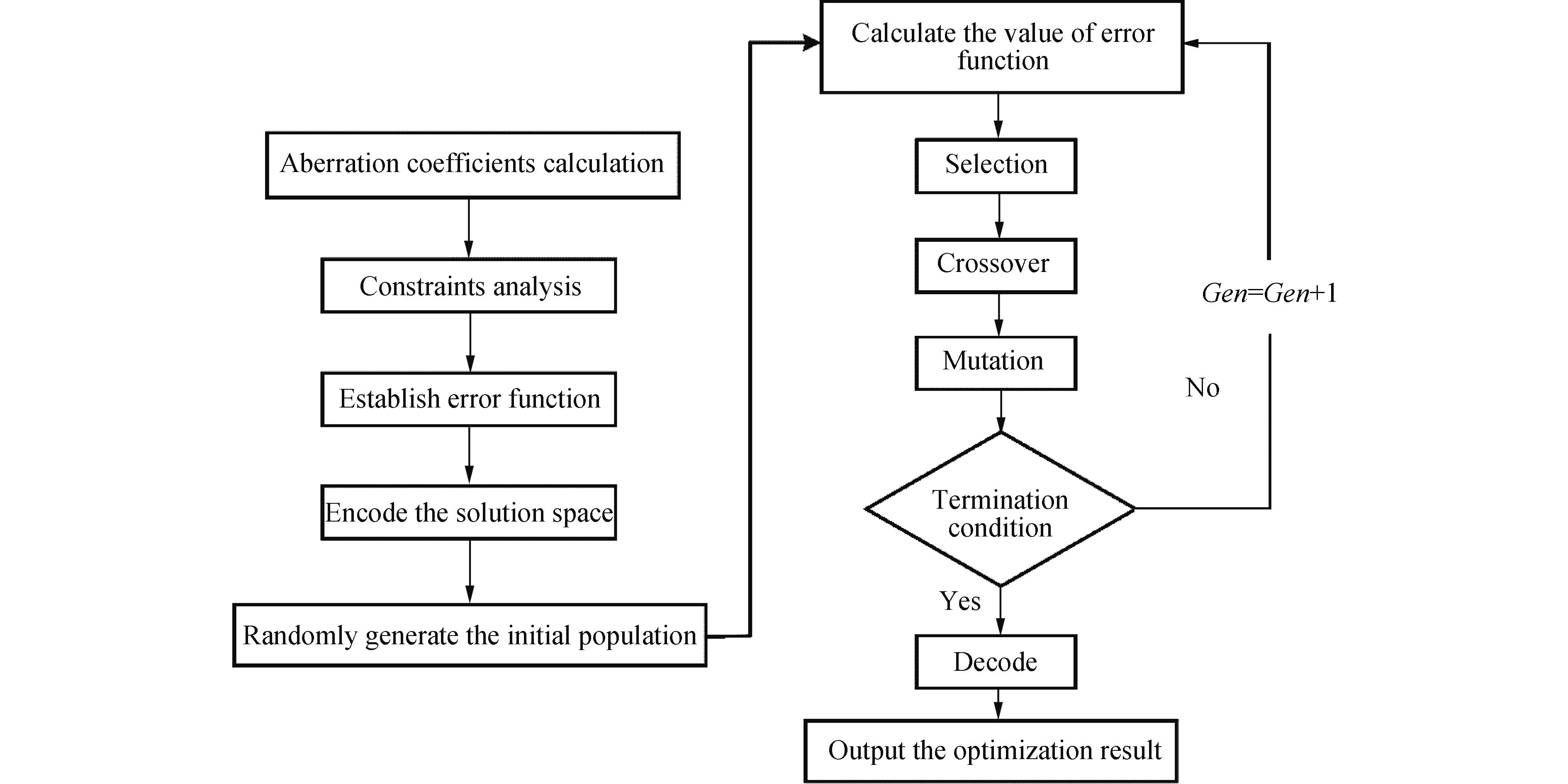
    Fig. 1. Flow chart of design process
    Change trend of RMS diameter of spot diagram
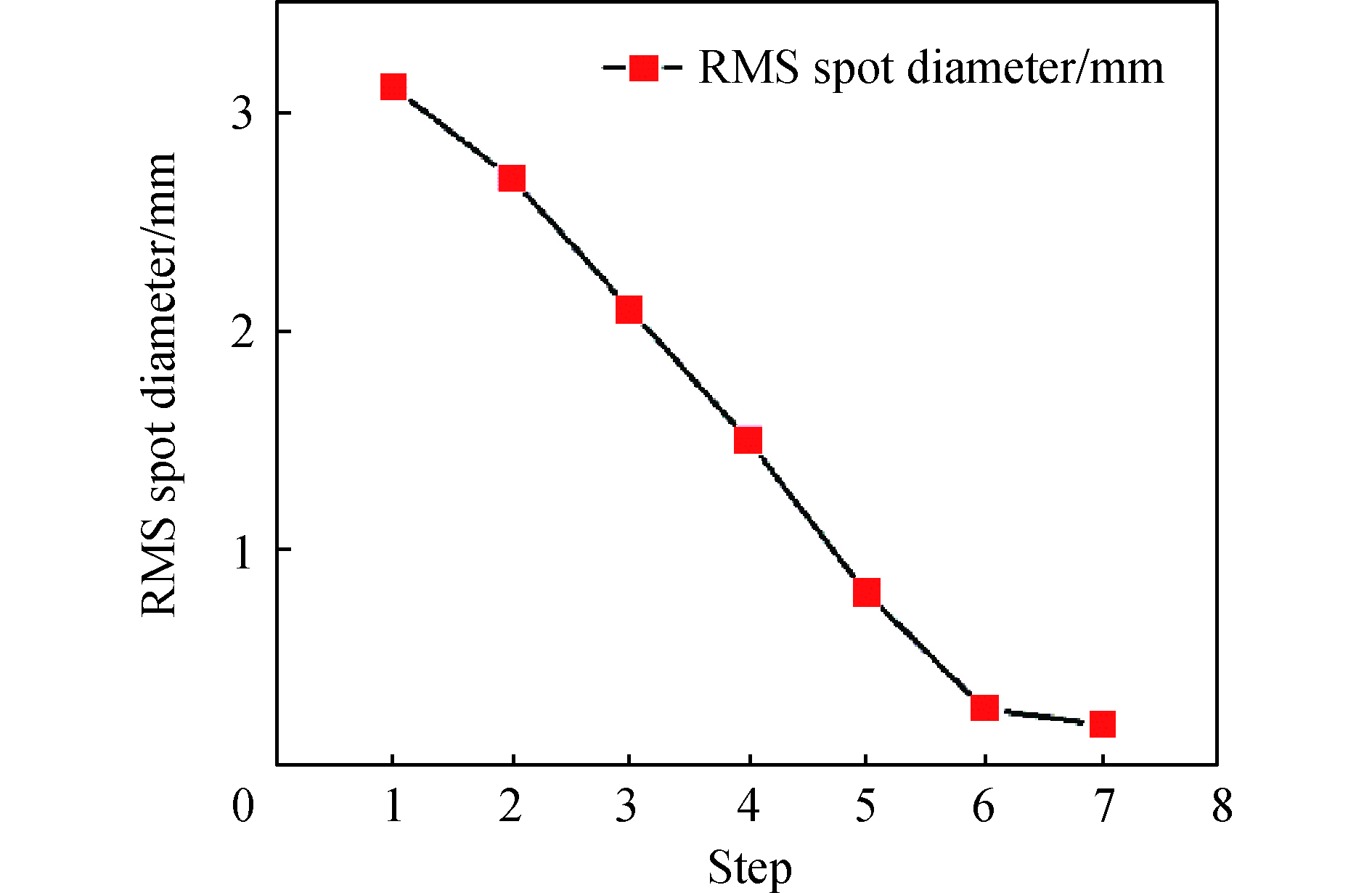
    Fig. 2. Change trend of RMS diameter of spot diagram
    Interval constraint range
    Fig. 3. Interval constraint range
    In-progress and final results for design of the initial configuration. (a) Initial system; (b) Results for system construction using Φ(X1, Y1); (c) Final result
    Fig. 4. In-progress and final results for design of the initial configuration. (a) Initial system; (b) Results for system construction using Φ(X1, Y1); (c) Final result
    Field map of RMS wavefront error for final system
    Fig. 5. Field map of RMS wavefront error for final system
    MTF for the final system
    Fig. 6. MTF for the final system
    Encircled energy distribution of all field
    Fig. 7. Encircled energy distribution of all field
    (a) PM 3D free-form surface; (b) SM 3D free-form surface; (c) TM 3D free-form surface
    Fig. 8. (a) PM 3D free-form surface; (b) SM 3D free-form surface; (c) TM 3D free-form surface
    Tolerance probability curve
    Fig. 9. Tolerance probability curve
    TermZernike polynomial XY polynomial Corresponding aberration type
    1Piston(constant)
    0th order in wavefront
    2Distortion-tilt(x-axis)
    2nd order in wavefront
    3Distortion-tilt(y-axis)
    2nd order in wavefront
    4Defocus
    2nd order in wavefront
    5Astigmatism, primary (axis at 0°or 90°)
    4th order in wavefront
    6Astigmatism, primary (axis at ±45°)
    4th order in wavefront
    7Coma,Primary(x-axis)
    4th order in wavefront
    8Coma,Primary(y-axis)
    4th order in wavefront
    9Spherical aberration,Primary
    4th order in wavefront
    Table 1.

    Zernike polynomials and XYpolynomials correspond to aberration relations

    Zernike多项式与XY多项式对应像差关系

    ParameterSpecification
    Wavelength range/μm8-12
    Focal length/mm400
    F-number 2
    Field of view
    Pixel size/μm30
    Table 2.

    Optical system specification

    光学系统参数

    ParameterRangeResult
    d1/mm [−250,−100]−201.4271
    d2/mm [100,250]210.6225
    r1/mm [−800,−50]−780.0523
    r2/mm [−800,−50]−115.2459
    r3/mm [−800,−50]−279.4206
    k1[−10,10]9.0266
    k2[−10,10]2.5360
    k3[−10,10]0.1883
    α1/(°) [10,30]15
    α2/(°) [10,30]25.0181
    α3/(°) [10,30]10.0006
    Table 3.

    Ranges of configuration parameters and optimization result

    解空间结构参数范围和求解结果

    SurfaceR/mm KRMS surface error(λ=9 μm) DisplacementTilt
    X/μm Y/μm Z/μm X/(″) Y/(″) Z/(″)
    PM0.020.10%1/50λ202025303020
    SM0.050.05%1/40λ404020202020
    TM0.050.10%1/50λ202020202030
    Table 4.

    Tolerances distribution of the system

    系统公差分配表

    Cumulative probabilityChange in MTF
    F1F2F3F4F5F6F7F8F9
    50.0%0.002 40.004 30.004 60.010 50.006 40.012 80.015 60.007 60.005 4
    84.1%0.012 70.012 50.017 40.036 80.017 70.024 50.038 90.026 30.024 7
    97.7%0.018 50.025 60.029 80.073 70.028 80.039 70.062 20.045 00.031 6
    99.9%0.022 40.037 80.052 50.103 00.048 40.068 50.098 40.063 70.046 7
    Table 5.

    Tolerances performance of all field

    全视场公差变动表现

    Bingxu Chen, Zhiyuan Liao, Chao Cao, Yu Bai, Da Mu. Design of the freeform imaging system with large field of view and large relative aperture[J]. Infrared and Laser Engineering, 2020, 49(8): 20200005
    Download Citation