• Laser & Optoelectronics Progress
  • Vol. 58, Issue 7, 0713001 (2021)
Erpan Fan1 and Yuntuan Fang1、2、*
Author Affiliations
  • 1School of Computer Science and Telecommunication Engineering, Jiangsu University, Zhenjiang , Jiangsu 212013, China
  • 2Key Laboratory of Intelligent Computing & Signal Processing, Ministry of Education, Anhui University, Hefei , Anhui 230039, China
  • show less
    DOI: 10.3788/LOP202158.0713001 Cite this Article Set citation alerts
    Erpan Fan, Yuntuan Fang. Optimal Design of Topological Boundary States with Large Bandwidth and Intense Localization[J]. Laser & Optoelectronics Progress, 2021, 58(7): 0713001 Copy Citation Text show less
    Structure of the lattice. (a) Triangular compound lattice; (b) first Brillouin zone of the lattice and three high symmetry points
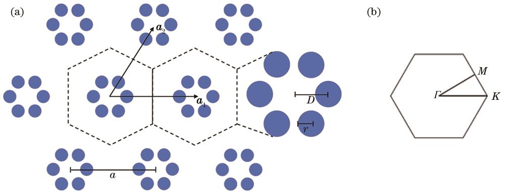
    Fig. 1. Structure of the lattice. (a) Triangular compound lattice; (b) first Brillouin zone of the lattice and three high symmetry points
    Energy band and orbit of the initial structure. (a) r = 0.06a, D = 0.12a; (b) r = 0.06a, D = 0.44a
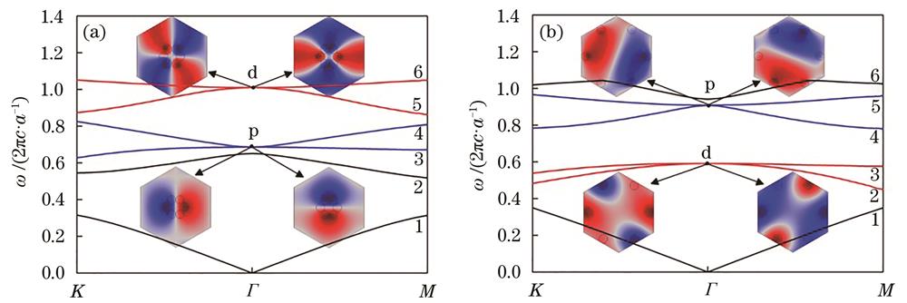
    Fig. 2. Energy band and orbit of the initial structure. (a) r = 0.06a, D = 0.12a; (b) r = 0.06a, D = 0.44a
    Change curves of the energy band frequency with zooming distance D at different r. (a) r = 0.06a; (b) r = 0.057a; (c) r = 0.02a
    Fig. 3. Change curves of the energy band frequency with zooming distance D at different r. (a) r = 0.06a; (b) r = 0.057a; (c) r = 0.02a
    Curves of the frequency of the 3rd and 4th energy levels of the three high symmetry points with the dielectric cylinder radius. (a) Trivial state; (b) non-trivial state
    Fig. 4. Curves of the frequency of the 3rd and 4th energy levels of the three high symmetry points with the dielectric cylinder radius. (a) Trivial state; (b) non-trivial state
    Width of the common band gap versus the radiuses of two structures
    Fig. 5. Width of the common band gap versus the radiuses of two structures
    Energy band after optimized structure parameters. (a) Trivial state; (b) non-trivial state
    Fig. 6. Energy band after optimized structure parameters. (a) Trivial state; (b) non-trivial state
    Boundary state after optimization. (a) Supercell energy band diagram; (b) mode field at points A, B, C, and D in the boundary state mode and energy flux density vector at the boundary
    Fig. 7. Boundary state after optimization. (a) Supercell energy band diagram; (b) mode field at points A, B, C, and D in the boundary state mode and energy flux density vector at the boundary
    Transmission of the spin-locked boundary states. (a) Clockwise spin; (b) anticlockwise spin
    Fig. 8. Transmission of the spin-locked boundary states. (a) Clockwise spin; (b) anticlockwise spin
    Bending transmission of the spin-locked boundary states. (a) Clockwise spin; (b) anticlockwise spin
    Fig. 9. Bending transmission of the spin-locked boundary states. (a) Clockwise spin; (b) anticlockwise spin
    r2/ar1/a
    0.0690.0700.0710.072
    0.080023.0522.4221.7821.23
    0.081024.5723.1824.0321.97
    0.082024.5724.7523.3122.76
    0.082924.5924.6824.0623.48
    Table 1. Relative band gap width corresponding to the optimized radius of the two structures
    ReferenceBandwidth
    Ours0.0435
    Ref. [20]0.02
    Ref. [21]0.011
    Ref. [22]0.015
    Ref. [23]0.03
    Table 2. Bandwidth of different topological boundary states
    ReferenceLocality
    Ours2a
    Ref. [24]6.7a
    Ref. [25]4a
    Ref. [26]7a
    Ref. [27]12.1a
    Table 3. Locality of different topological boundary states
    Erpan Fan, Yuntuan Fang. Optimal Design of Topological Boundary States with Large Bandwidth and Intense Localization[J]. Laser & Optoelectronics Progress, 2021, 58(7): 0713001
    Download Citation