1Key Laboratory of Photonics Control Technology, Ministry of Education, Tsinghua University, Beijing 100084, China
2Department of Precision Instrument, State Key Laboratory of Precision Measurement Technology and Instruments, Tsinghua University, Beijing 100084, China
3Beijing Institute of Control Engineering, Beijing 100190, China
4Beijing Institute of Electronic System Engineering, Beijing 100854, China
Kaige Liu, Hengkang Zhang, Shanshan Du, Zeqi Liu, Bin Zhang, Xing Fu, Qiang Liu, "Particle manipulation behind a turbid medium based on the intensity transmission matrix," Photonics Res. 10, 2293 (2022)
Copy Citation Text
Although optical tweezers can manipulate tiny particles, the distortion caused by the scattering medium restricts their application. Wavefront-shaping techniques such as the transmission matrix (TM) method are powerful tools to achieve light focusing behind the scattering medium. In this paper, we propose a method to focus light through a scattering medium in a large area based on the intensity transmission matrix (ITM). Only relying on the intensity distribution, we can calculate the ITM with the number of measurements equal to that of the control segments. Free of the diffraction limit, our method guarantees high energy usage of the light field. Based on this method, we have implemented particle manipulation with a high degree of freedom on single and multiple particles. In addition, the manipulation range is enlarged more than 20 times (compared to the memory effect) to 200 μm.
1. INTRODUCTION
Optical tweezers use the interaction between light and matter to manipulate particles on the wavelength scale. The path of the photon is deflected as it passes through a particle, while the transfer of the momentum forces the particle to move away from the direction of deflection. Thus, a Gaussian-focused beam can create potential optical traps to bind or manipulate particles [1,2]. Optical tweezers have achieved a wide range of applications in biomedicine [3–6], precision measurement [7–9], nanotechnology [10,11], and many other fields [12–15]. Optical tweezers impose high demands on the stability of the system and the environment, and the light field distribution at the focal point has a great impact on the manipulation quality [16]. However, the prevalence of the scattering medium disrupts the distribution of the optical wavefront, making the focused beam a diffuse patch of light. Although scattered light fields can also be used to manipulate particles, the scattering effect causes the dispersion of energy and the irregularity of the spot shape, resulting in a less accurate and capable manipulation [17]. Therefore, achieving a high-quality optical focus behind a turbid medium will greatly expand the application range of optical tweezers.
In recent years, studies on the scattering effect have shown that light propagation in a stable scattering medium is a stationary process [18,19]. Using wavefront-shaping techniques, one can effectively compensate for the aberration induced by light scattering in a turbid medium to achieve focus or special light field distribution at the target location [20–23]. In 2010, Čižmár et al. used the stepwise sequence algorithm for phase optimization to achieve light focusing behind a turbid medium and used this focus to implement particle manipulation [24]. In 2019, Peng et al. used an improved genetic algorithm (GA) to achieve single-point and multipoint focusing and proceeded with particle binding and manipulation [25]. They both relied on iterative optimization algorithms that set a specific target distribution of the light field and then are optimized to approach it by iteratively changing the modulation mask based on the difference between the output light field and the targeted one. The memory effect of the scattering medium demonstrates that the output light will maintain the same motion when the input light is spatially moved or angularly tilted in a small range [26,27]. This feature can be used to move the light focus and thus manipulate the particles. However, the manipulation range of this method is usually small and is limited by the range of the memory effect. In addition, when dealing with multiparticle manipulation, each particle can only maintain the same movement as the input light, and cannot have its own individual trajectory, which greatly limits the freedom of multiparticle manipulation [25].
For particle manipulation, we usually wish to manipulate particles in a large range and with a high degree of freedom and flexibility. We are aware that the transmission matrix (TM) method, another powerful tool for wavefront shaping, can achieve focus in large fields of view and multiple independent points [21,23,28–30]. It is an ideal tool for particle manipulation in scattering environments. However, the transmission matrix method requires measurement of the response of a set of spatially complete orthogonal bases, which usually takes a lot of time and limits the optimization efficiency in practical applications [23]. This makes it difficult to apply this technique to dynamic media such as biological tissues. Therefore, a method that can quickly compute and obtain the TM is still desired.
Sign up for Photonics Research TOC. Get the latest issue of Photonics Research delivered right to you!Sign up now
Thanks to the rapid development of modulation devices, the application of digital micromirror devices (DMDs) greatly reduces the time required for measurements compared to a liquid crystal spatial light modulator (LC-SLM) by increasing the refresh frequency to tens of kilohertz [31]. Computational holography is usually needed to generate phase modulation from the binary modulation of DMD. However, due to the diffraction efficiency limitation, about 90% of the light is wasted [32]. This poses a great difficulty for the application of optical tweezers, which are highly dependent on the focal light intensity. A continuous sequential (CS) algorithm [22] can achieve focus without diffractive optical paths, but it is limited by the SNR. Afterward, the Hadamard multiplexing [33] method was proposed. With the use of the Hadamard basis, this method achieves focus with high speed and gets rid of the limitation of the SNR. However, both of them set the targeted focus position, which corresponds to the measurement of a row in TM. It makes them suffer from the same range limitation of the memory effect as the iterative algorithm and cannot move the focus over large areas. Phase retrieval algorithms [34,35] have been proven to be able to measure the complex valued TM with binary modulation, but the iterative process makes them time-consuming and prone to fall into the local minimum. The real-valued TM method [36] requires twice as many measurements as the number of control segments. As a result, it takes more time to do the measurements.
In this paper, we propose what we believe, to the best of our knowledge, is a new method to focus behind the scattering medium in a large area with binary modulation based on the TM method. By analyzing the link between the intensity distributions of the input and output, we establish the intensity transmission matrix (ITM) comprising only real-valued elements. After a number of measurements equal to that of the control segments, the obtained ITM can realize focus in a wide range. In addition, it does not use the diffractive optical path, thus avoiding the loss of energy in diffraction and largely enhancing the light intensity of the focus [32]. In the remaining sections of this paper, we will first detail the theoretical framework of the ITM, including the theoretical prediction for the peak-to-background ratio (PBR) of the focus. Based on this theory, we implemented particle manipulation experiments, achieving both a large manipulation range and a high degree of freedom during multiparticle manipulation. We believe that this theory provides a new approach to make full use of the energy transported through the scattering medium with high speed. It will be significant for the application of optical tweezers in a scattering environment.
2. PRINCIPLES
The determination of the TM requires a set of spatially complete bases. Here, we choose Hadamard bases. The two states of the DMD modulation cell correspond to 0 and 1 in amplitude modulation, so we replace all elements in the Hadamard bases with 0 elements. The altered Hadamard bases are still a spatially complete matrix, and linear combinations of its column vectors can make up any modulation mask, so where is an N-order vector recording the input modulation mask, are the altered Hadamard bases, and is an N-order vector.
To establish the relationship between the ITM and the altered Hadamard bases, we start with the conventional complex TM. In conventional TM theory, the measured output light field is in complex form, with [23] where is an M-order vector recording the output light field of the input , and is an matrix recording all the output light fields.
According to the time reversal, we can get the modulation mask corresponding to the target output [21]: where denotes the transpose conjugate, and TM can be expressed as where is the conventional Hadamard basis, and is the -th element in the output light field corresponding to the first Hadamard vector. Then, we discuss the calculation of the ITM removing the phase information. The DMD panel was subdivided into several equally sized squares, which are usually dubbed superpixels or control segments. We use the term “control segment” in the remaining part of this paper. The subtracted term on the right side of Eq. (7) only affects the magnitude of the first column of TM, which represents the transmission from the first control segment in DMD to different output modes. In Hadamard bases, the first control segment always stays on and can be seen as the reference. Therefore, the first control segment can remain on while determining the optimization mask for focusing. As a result, this subtracted term, which only makes sense in deciding the first control segment, is not necessary when calculating the optimization mask and can be ignored.
The mask corresponding to focus at the -th output mode is obtained from the -th row in TM. Since the output light field is complex-valued, the target output obtained from the linear combination of is consistent with the coherent superposition in the optical transmission process, and the calculated input mask is also the theoretically optimal one [23]. However, if no phase measurements are made, the TM is calculated by relying only on the intensity distribution; in other words, is real-valued. It is important to note that the time reversal still holds, since it is equivalent to taking a mode on both sides of the equation, and the equation still holds when both are real numbers.
To verify the effectiveness of ITM in wavefront shaping, we first consider the distribution of elements in the ITM:
If our target focus is placed at the -th output mode, we still extract the -th row of the ITM: where is the amplitude of the -th output mode with the -th column vector in Hadamard bases entering. Then, we decide which control segment should be turned on, based on its influence on the intensity at target output mode: where is the element of the -th row and -th column in the ITM, and is the -th column vector in Hadamard bases. Here. takes 1 and corresponding, respectively, to 1 and 0 in the altered Hadamard bases. For example, if when , then it corresponds to the case where the -th control segment is turned off when the -th Hadamard vector is input. At this point, the light field at the -th control segment is not involved in the intensity superposition at the target output mode. Therefore, is not affected by the light field at the -th control segment; that is, all the terms corresponding to the value of that match are obtained with the -th control segment turned off. On the contrary, the ones corresponding to are obtained while the -th control segment is turned on. For Hadamard bases, control segments turned on and off are split in half disregarding the first one. Therefore, the Eq. (11) is converted into the difference of the mean value of the amplitude at the target output mode when the -th control segment is turned on and off. Since N is much larger than 1, the control segments other than the -th one can be regarded as being randomly turned on and off in both cases. Therefore, the above equation can be translated to where is one of the TM elements, (the first control segment is always on), and denotes the statistical average.
When , the turning on of the -th control segment causes the mean value of the intensity at the -th output mode to be boosted. So, the -th control segment has a positive effect on the focus and should be turned on. Based on the sign of , we can qualitatively estimate the effect of all the control segments on the target output mode and thus obtain the input mask to achieve focusing.
Finally, to evaluate ITM’s ability to focus, we can use the statistical properties of the scattering medium to calculate the theoretical value of PBR, which is defined as [22] where and are the intensity of the focus and the averaged background.
Under the condition of , Eq. (12) is equivalent to
According to the first-order statistical properties of the scattered light field, we can obtain the joint probability density function of the real and imaginary parts of each point in the scattered light field [37]: where and are, respectively, the real and imaginary parts of the output light field, and is the variance of the Gaussian distribution. Then, we can calculate the values on both sides of the Eq. (15):
If the control segment has a positive effect, we get
Here, is taken as the statistical average: where and are, respectively, the amplitude and phase of the . Therefore, the value of must satisfy
From the probability density function [Eq. (16)], the statistical characteristics of can be calculated by where is the possibility for any control segment to be turned on, and and are, respectively, the amplitude and phase of the . Thus, the focus intensity at the -th output mode can be derived from the superposition of the complex distributions of the control segments turned on as where is the normalization factor, and is the number of control segments turned on. The statistical mean of the focus points is
The average intensity of the background field is and the focus PBR is
The theoretical PBR for binary modulation using a complex form transmission matrix is [22]
The theoretical PBR of the ITM is about 1/2 of the conventional one.
3. EXPERIMENT
A. Experimental Setup
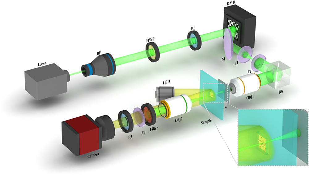
The experimental setup is shown in Fig. 1. In our experiment, a 532 nm laser (homemade, solid-state, continuous wave) with a maximum output power of 6 W was employed as the light source. It was first expanded by a beam expander and then went through the combination of a half-wave plate and a polarizer to modulate the polarization state. The modulator was a high-speed DMD (V7001, ViALUX; resolution: , pixel size: μμ), which selected part of the beam to reflect it into the subsequent system. A telescope system (, ) and a 50:50 beam splitter (BS) were employed to image the modulation mask on the aperture of the objective (Obj1, TU Plan ELWD , Nikon, ). Then the modulated beam was focused onto the scattering medium by the objective. The scattering medium was a ground glass scatterer (120 grits, Edmund Optics), through which the light was scattered. The scattered light then passed through the particle sample (5 μm diameter, polystyrene) in water accommodated by a slide and coverslip. Another objective (Obj2, MPLAN-N , Olympus, ) and a tube lens () were used to image the transmitted light to a CMOS camera (edge 4.2 bi, PCO; pixel size: μμ), and used as the microscopic objective for the observation of particle sample motion. The LED was used to provide illumination while manipulating the particle. When observing the particle movement, the 532 nm light was blocked by a 532 nm centered band-blocking filter to improve the observation contrast. The control program for the camera and DMD was written in C (Visual studio 2019 community).
B. Intensity Transmission Matrix
We first experimentally verified the ability of the ITM in light focusing behind the scattering medium. The ITM was measured using the altered Hadamard bases of order 4096, indicating that the number of control segments was . In this case, the central pixels were selected as the modulation area. We divided this area into 4096 segments in which the adjacent pixels have the same modulation state. Then, we loaded these modulation masks sequentially onto the DMD and acquired the corresponding speckle patterns with the camera. We can select any pixels in the camera as the output, which then determine the focus range. Here, we selected 4096 pixels in the central part of the camera and then transformed them to 4096 order vectors. These vectors were arranged to form the ITM. With only 4096 measurements, we obtained the full-sized ITM with a order. Using time reversal, an optimized mask to focus at the target output mode could be calculated. Then, we loaded the mask on the DMD, and the focused spot was observed on the image plane. The normalized light field distribution before and after optimization is shown in Figs. 2(a) and 2(b), respectively. To quantitatively evaluate the contrast between the focus and the background, we calculated the PBR defined in Eq. (13). The light intensity was determined by the grayscale value of the pictures taken by the camera. In our experiment, we got a PBR of 215.66. The theoretically predicted value could be calculated according to the previously inferred theoretical value of PBR by Eq. (30); i.e., . In addition, this method can also achieve multipoint focusing when the target output light field increased to several points. The results are shown in Fig. 2(c). The corresponding PBRs at three focal points were 71.27, 70.13, and 75.59, respectively.
Figure 1.Experimental setup. F1, F2, and F3, lens; HWP, half-wave plate; P1 and P2, polarizer; BE, beam expander; M, mirror; BS, beam splitter; S, scattering medium; and Obj, objective lens.
Figure 2.Focusing result with ITM. (a) Speckle pattern before optimization. (b) Experimental result and target output light field of single focus. (c) Experimental result and target output light field of multiple foci. (d) PBR with different number of control segments in theory, simulation, and experiment. (e) Comparison of TM and ITM in terms of PBR. (f) Comparison of TM and ITM in terms of focus intensity.
When we changed the number of the control segments and performed focusing experiments using different orders of Hadamard bases, we obtained the PBR curve, as shown in Fig. 2(d). When the number of the control segments was small, the PBR agreed well with the theoretical prediction. However, when the number of the control segments was large, the PBR of the focus was lower than the theoretical value. This error was attributed to the speckle decorrelation [38] and the measurement noise in the experiment [22]. We also used the angular spectrum method [39] to simulate the process of light focusing under ideal conditions. The parameters of the simulation were initialized to meet the experimental conditions. The incident beam was 532 nm with a diameter of 1 μm. The scattering medium has the transport mean free path μ and the thickness of μ. The scattering medium was divided into 20 pieces in the transmission direction. It has a mean refractive index of 1.4. The simulation results of focusing with a different number of control segments agreed well with the theoretical prediction.
In particle manipulation, the light intensity at the focal point is an important factor in determining the magnitude of the light force. We experimentally compared the focusing effect of ITM and TM. For the TM measurements, we used computational holography and filtered out the diffracted light, except for the level [32]. The other parts of the experimental setup were kept consistent with the ITM measurements. We also used the same camera exposure time in all the control experiments, so we could obtain the intensity of the focus visually from the grayscale value in the picture. Due to the absence of phase information, the PBR of the focus achieved by the ITM was only 0.45 to 0.5 times that of the TM, as shown in Fig. 2(e). This result was consistent with our theoretical prediction. However, because of the limitation of the diffraction efficiency, only about 10% of the light can be effectively used [32]. Therefore, the light intensity of both the focus and the background was relatively low in the TM focusing experiments. The background light intensity in the ITM experiment was 9.18 times higher than that of TM, and the focus intensity was about 3.7 to 4.6 times higher, as shown in Fig. 2(f). Therefore, although the PBR of the ITM was lower than that of the TM, the light intensity of the achieved focus was increased by several times, greatly improving the light force in the particle manipulation.
C. Particle Manipulation
The ITM method allows for rapid acquisition of single-point and multipoint focus close to the diffraction limit. The large light intensity gradient can be used to capture particles undergoing Brownian motion in liquid. The particles can be captured by the focus as they move randomly near the focus and will be stably bound to the focus [1,2]. Due to the low NA objective used in the experiment, the particles were also subjected to a force in the direction of the beam propagation because they are attracted to the center of the beam. Thus, we set the observing plane at the upper edge of the sample to ensure the stability of particles in the direction of beam propagation. As the focus is moving, the particle will be dragged to the center of the focus continuously, thus moving in the same path as the focus.
After the transmission matrix was measured, we calculated the optimized masks to focus at different output modes and then loaded these masks sequentially onto the DMD to achieve an arbitrary trajectory movement of the focal point on the imaging plane, which is perpendicular to the direction of the light beam propagation. With this method, we could move the focus in a large range. Without the limitation of the memory effect, the range of the manipulation could be enlarged to 200 μm. We pulled the particle in a straight line from the left of the imaging plane to the right for about 200 μm (see Visualization 1), as shown in Fig. 3. And, with a larger imaging area and more output modes, the range of manipulation could be further expanded.
Figure 3.Particle manipulation with single particle along a straight line.
Figures 4(a)–4(e) show particle manipulation with special trajectories (see Visualization 2). In addition, using the results of multifocusing, we could manipulate multiple particles at the same time. When calculating the optimization mask, the positions of the multiple targets were calculated independently, allowing multiple particles to move independently with their own trajectories. When performing multiparticle manipulation, each particle could operate independently and would not be affected by the other particles. Figures 4(f)–4(j) show the result of manipulating two particles moving around a circle (see Visualization 3).
Figure 4.Particle manipulation. (a)–(e) Single focus with a square path. (f)–(j) Double foci with a circle path.
During the process of particle manipulation, fluctuations of the focus intensity cause changes in the gradient force, which refers to the force generated by the focus that pulls the particles toward the center of the focus. When the gradient force decreases, the particles will have a higher probability of escaping the bindings [40]. In the memory effect, the variation of the focus intensity depends on the distance away from the original focus. As the distance increases, the intensity decreases smoothly [25]. In contrast, the focus achieved by ITM does not depend on the distance but is limited by the inhomogeneity of the focus intensity at different points.
To evaluate the stability of the particle manipulation, we measured the focus intensity at different output modes. We can select any pixels in the pictures captured by the camera as the output modes. In our experiment, most of the energy of the light field after traveling through the scattering medium was in the area of pixels in the center of the camera. First, we selected pixels at intervals in this area to examine the focus effect in a large area. Here, we selected pixels at intervals of 10 pixels. After that, we selected the center pixels without intervals to examine the focus effect more finely in a smaller area. In both cases, we obtained output modes, measured the ITM separately, and achieved focus at all output modes. By recording the PBR values of all focus, we obtained the planar distribution of the PBR. The PBR distribution in a large and small area is shown, respectively, in Figs. 5(a) and 5(b). To quantitatively evaluate the fluctuation of the focus intensity at different output modes, we calculated the mean value and variance of the PBR in circular regions with a different radius in pixels, as shown in Fig. 5(c). Among them, for the discussion of the mean value, we divided into two cases. One was to average the PBR of the pixels on the edge of the circular region to evaluate the range of particle manipulation. The other was to average over all pixels in the circular region to evaluate the particle manipulation ability within different sizes of regions. As the radius increased, the mean value within the region showed a decreasing trend. This was because the beam was first focused by the objective lens and then scattered by the scattering medium. The concentration of energy still tended to be in the form of a Gaussian distribution. Therefore, the closer to the edge part of the imaging plane, the less energy could be optimally converged to, and the lower the PBR of the focus obtained. The variance in the region stayed at a low level, almost constant with increasing radius. This was due to the inhomogeneity of the focus intensity distribution caused by the inhomogeneity of the incident light field and the errors introduced by environmental perturbations. The variance of selecting pixels without intervals was lower overall compared to that with intervals. Although the variance of both was close at a large pixel radius, the former could get a very low variance at a small pixel radius. Therefore, selecting output modes without intervals in pixels could reduce the instability in the particle manipulation process. In addition, the output modes in this case had a smaller spatial distance between modes and were less likely to lose particles during focus shifting.
Figure 5.Moving focus with ITM and memory effect. (a) and (b) Uniformity of PBR focused by ITM ( output modes) at different output modes selected with, respectively, intervals of 10 pixels and without intervals. (c) Mean value and variance of the focus PBR with ITM. (d) Moving focus with memory effect. The dashed circles and arrows indicate the vertical axes corresponding to the curves.
The intensity on the edge of the circular region determines the range of particle manipulation. It showed a gradual decrease along the radial direction and dropped to half at the radius 68 μm. At a radius of 104 μm, the mean value of PBR decreased to 32.5%. The farther the scattering medium was placed from the focal point of the focusing objective, the larger this width became. In addition, it also led to a decrease in the focal energy. Therefore, when performing particle manipulation, we must choose appropriate system parameters to obtain the best manipulation performance. In addition, we tested the range of movement of the memory effect under our experimental conditions. By shifting the position of the beam entering the scattering medium within a small range, we observed the following shift of the focal point. The further away from the original position, the lower the intensity was, as shown in Fig. 5(d). Based on the formula for the memory effect [26,27], where is the focus intensity, is the wave factor, is the angle of deviation from the initial position, and is the effective thickness, we fitted the theoretical curve. Its FWHM was 6.2 μm, and the intensity decreased to less than 1/3 of the peak value outside the 7.5 μm range. Therefore, compared to the memory effect, the manipulation range could be extended by more than 20 times using ITM.
5. SUMMARY
In this paper, we proposed a new method to focus behind a scattering medium based on the measurement of ITM. It only demands a number of measurements equal to that of the control segments. In addition, there is no diffraction limitation in this method, thus promising high usage of the light field energy. Based on the ITM, we achieved single-point and multipoint focusing. Then, we applied the ITM to particle manipulation, taking advantage of its large range and a high degree of freedom in manipulation. The manipulation range was enlarged more than 20 times to about 200 μm compared to the memory effect. Furthermore, multiple particles could be manipulated at the same time with their own trajectories.
Kaige Liu, Hengkang Zhang, Shanshan Du, Zeqi Liu, Bin Zhang, Xing Fu, Qiang Liu, "Particle manipulation behind a turbid medium based on the intensity transmission matrix," Photonics Res. 10, 2293 (2022)