Realizing a large-scale fully controllable quantum system is a challenging task in current physical research and has broad applications. In this work, we create a reconfigurable optically levitated nanoparticle array in vacuum. Our optically levitated nanoparticle array allows full control of individual nanoparticles to form an arbitrary pattern and detect their motion. As a concrete example, we choose two nanoparticles without rotation signals from an array to synthesize a nanodumbbell in situ by merging them into one trap. The nanodumbbell synthesized in situ can rotate beyond 1 GHz. Our work provides a platform for studying macroscopic many-body physics and quantum sensing.
1. INTRODUCTION
Optical levitation employs forces exerted by strongly focused light fields to capture and manipulate microparticles and nanoparticles [1–3]. As a result, an optically levitated system is naturally isolated from environmental disturbances. In particular, it possesses extremely low damping in high vacuum and thus has an ultrahigh mechanical quality factor as an excellent optomechanical system. Hence, this system has attracted abroad attention and provides a powerful platform for precision measurements [4–7] and fundamental physics investigations [8–11]. The center-of-mass (CoM) motion of an optically levitated nanoparticle has been cooled to the quantum ground state [12–14], and can be used to generate non-Gaussian macroscopic quantum states in the future. Besides CoM motion, libration [15], rotation [16], and their coupling with internal degrees of freedom (e.g., phonons, magnons, spin defects) of the levitated nanoparticle also provide rich physics to explore. In particular, the free rotation of a rigid body exhibits fascinating behaviors in both classical and quantum regimes due to its nonlinear dynamics. Researchers can now drive a single levitated nanoparticle to rotate at GHz frequencies [17–20], control its rotation with ultrahigh precision [16,21], and cool its librations to sub-kelvin temperatures [22,23].
In this work, we report the creation, detection, and rearrangement of an array of optically levitated nanoparticles in vacuum. Ultracold atoms and molecules in an array of optical tweezers in vacuum have provided a versatile platform for large-scale quantum simulation and quantum computing [24–28]. There is also significant progress in optical manipulation of multiple microparticles and nanoparticles in a liquid [29–33]. Recently, light-induced dipole–dipole interaction between two optically levitated nanoparticles in vacuum has been demonstrated [34–36]. However, creating a reconfigurable array of optically levitated nanoparticles in vacuum is still challenging due to the difficulty of loading multiple optical tweezers simultaneously and the lack of damping in vacuum to stabilize the system. Here, we utilize a high NA objective lens to tightly focus laser beams in the vertical direction against gravity to create the array of optical tweezers. In this layout, the tightly focused optical tweezers provide large gradient forces for trapping, and gravity helps to compensate for the scattering force and photophoretic force to stabilize the system [20,37,38]. As a result, our optical tweezers array can levitate silica nanoparticles at low pressures without feedback cooling. We employ an auxiliary trapping beam to move and rearrange the nanoparticles to the desired patterns after a stochastic loading process via ultrasonic atomization. Therefore, by this “post-processing,” a controllable loading of a predefined trapping array can be realized. In addition, we use an independent detection laser beam to monitor the motion of each nanoparticle in the array. As an application of this technique, we choose two nanoparticles without rotational signals in an array to synthesize a silica nanodumbbell in situ, and drive the created nanodumbbell to rotate at GHz frequencies. On-demand assembly of optically levitated nanoparticle arrays in vacuum will be important for creating macroscopic quantum entanglement [8–11] and studying complex phases of interacting systems [34,35,39–42].
2. EXPERIMENT OF TRAPPING A NANOPARTICLE ARRAY
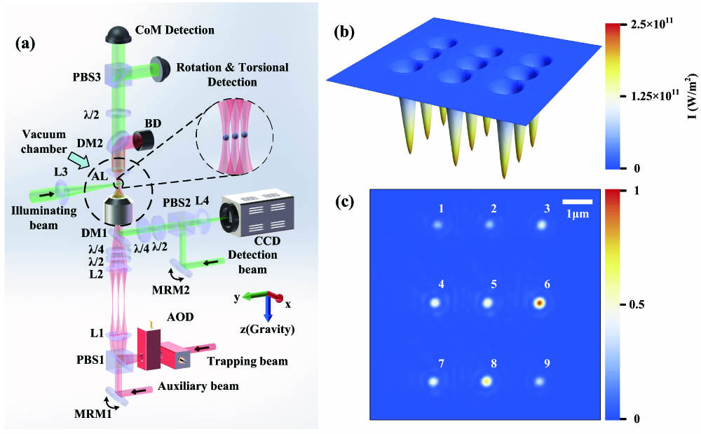
The experimental protocol is illustrated in Fig. 1(a). A two-dimensional (2D) array of 1064 nm laser beams is created by a pair of orthogonal acousto-optic deflectors (AODs) driven by a multitone radio frequency (RF) signal. The resulting beams are focused by an NA 0.95 objective lens to create an array of optical tweezers in a vacuum chamber. The optical tweezers propagate along vertical direction against gravity. The power of each trapping beam is about 200 mW. More details can be found in Section 5. Figure 1(b) shows a simulated intensity distribution of a array of optical tweezers for single 170 nm nanoparticles. An auxiliary 1064 nm laser controlled by a motor-driven reflective mirror is used to rearrange nanoparticles into arbitrary patterns on demand. In addition, we use a 532 nm detection beam to measure the motion of trapped nanoparticles and another 532 nm illuminating beam for imaging. A photo of nine nanoparticles trapped in a array is shown in Fig. 1(c). The horizontal distance of two adjacent columns is 1.77 μm, and the vertical distance of two adjacent rows is 2.66 μm.
Sign up for Photonics Research TOC. Get the latest issue of Photonics Research delivered right to you!Sign up now
Figure 1.Experimental setup and image of an optically levitated nanoparticle array. (a) The 2D trap array is produced by passing a 1064 nm laser through a pair of orthogonal acousto-optic deflectors (AODs). The laser beams created by the AODs are imaged with a 4f image system onto a high NA () objective lens, which creates an array of tightly focused optical tweezers in a vacuum chamber. The optical tweezers propagate against gravity. For particle assembly, we use an auxiliary moving tweezer at 1064 nm superimposed on the trap array with a polarized beam splitter (PBS1). This auxiliary beam is deflected by a motor-driven reflective mirror (MRM1). For particle motion detection, we overlap a probe beam at 532 nm with the trapping beams using a dichroic mirror (DM1). This 532 nm beam is deflected by another motor-driven reflective mirror (MRM2) to measure the motion of an arbitrary particle in the array. The 1064 nm trap beams and the 532 nm probe beam after the high NA objective are collimated by an aspherical lens (AL) and separated by another dichroic mirror (DM2) for detecting the motion of trapped nanoparticles. For particle imaging, an imaging beam at 532 nm is used to illuminate the particles orthogonally. The scattered light is collected by the same high NA objective to form an image on a charge-coupled device (CCD). , half-wave plate; L1–L4, spherical lenses; BD, beam dump. (b) Theoretically simulated intensity distribution of a two-dimensional (2D) array of optical tweezers. (c) Image of a array of optically levitated nanoparticles. The intensity is normalized.
We can use the auxiliary trapping beam to rearrange the pattern of an array. The power of the auxiliary beam is 400 mW. By controlling the orientation of this laser, we can transport and remove the nanoparticles at near atmospheric pressures with almost perfect success probabilities. Figure 2 shows an example of such an on-demand rearrangement. First, we load the nanoparticles into a array of optical tweezers as shown in Fig. 2(a) and Visualization 1 [43]. We can see that the initial filling of the array is probabilistic. Then we perform the rearrangement procedure to construct arbitrary and flexible patterns as shown in Figs. 2(b) and 2(c) and Visualization 2 [44].
Figure 2.Rearranging the pattern of a nanoparticle array. (a) Initial pattern of eight levitated nanoparticles in a array of optical tweezers. (b), (c) Rearranged patterns of the nanoparticle array. The intensity is normalized.
To exactly characterize each optically levitated nanoparticle in the array, we use a 532 nm probe beam to measure the CoM and torsional motions of each nanoparticle, as shown in Fig. 1 (a). The CoM and torsional motion signals for each nanoparticle in a array [Fig. 1(c)] at 2000 Pa are shown in Fig. 3(a). We find that the damping rates of the CoM motions in three directions (, , ) for the nanoparticles labeled “1,” “2,” “3,” and “7” are almost the same, and these nanoparticles have no signal of torsional motion, which implies that they are nearly spherical. However, the nanoparticles labeled “4,” “5,” “6,” and “8” display torsional motion signals, indicating anisotropy in their shapes. We consider a non-spherical nanoparticle with different sizes along three major axes. Note that a linearly polarized trapping laser is used here to generate torsional motion of the trapped nanoparticle. The longest axis with size of the nanoparticle will tend to align with the electric field of the linearly polarized laser, which is defined as the axis. This is because the polarizability of the nanoparticle along its longest axis is the largest [18]. The trapping frequencies of the CoM motion depend on the polarization of the trapping laser [45]. The smaller radial trapping frequency is along the electric field of the linearly polarized laser ( axis).
Figure 3.Characterization of each nanoparticle in an optically levitated nanoparticle array. (a) Power spectra of the CoM and torsional motions for the trapped nanoparticles as shown in Fig. 1(c) at 2000 Pa. Blue, red, and green traces correspond to power spectra of the CoM motions along the , , and axes, respectively. Pink traces are the power spectra of torsional motions. (b) Damping rates of the CoM motions for the nine trapped nanoparticles as a function of pressure. The dots are measured data, and the solid lines are linear fittings.
The damping rate of the CoM motion for a nanoparticle depends on the air pressure and its shape (, ). It is proportional to at low pressures when the mean free path of air molecules is much larger than the size of the particle. A larger size in one direction will lead to a smaller damping rate of the CoM motion along that direction [18,46]. Therefore, we can estimate the shape of the nanoparticle via the measured damping rates. Figure 3(b) shows the damping rates of CoM motion along three orthogonal directions as a function of pressure. When the damping rates of CoM motion along three orthogonal directions are almost the same [curves “1,” “2,” “3,” and “7” in Fig. 3(b)], we can infer that the shape of the nanoparticle is nearly spherical, which confirms the observation of no torsional signal for these nanoparticles. In contrast, damping rate ratios and of CoM motion are large for “4,” “5,” “6,” and “8” nanoparticles, which means these nanoparticles are anisotropic. This agrees with the observation of torsional motion for these nanoparticles in a linearly polarized laser.
3. ASSEMBLY OF A NANODUMBBELL
After we obtain an optically levitated nanoparticle array, we select two nanoparticles without torsional signals from the array to synthesize a nanodumbbell that supports fast rotation. Figures 4(a) and 4(b) illustrate the assembling process. First, we choose two nanoparticles from an array, which have no torsional motion signals as shown in Figs. 4(c)–4(f). Then we control the auxiliary trapping beam to move one of the two nanoparticles into the same trap. The two nanoparticles will stick together to become a nanodumbbell with 25% probability of success in a single trap. There are several other different situations for the two nanoparticles merged into a single trap. For example, the nanoparticles may be lost from the trap. The two nanoparticles may also remain separated in a trap, which may be due to the repulsive Coulomb force between them if they have the same sign of charges.
Figure 4.In situ synthesis of a nanodumbbell by merging two optically levitated nanoparticles. (a) Image of two separated nanoparticles in two optical tweezers. (b) Image of the assembled nanoparticle. The intensity is normalized in (a) and (b). (c)–(f) CoM motion signals and corresponding damping rates as functions of the pressures for nanoparticles 1 and 2, respectively. (g), (h) CoM motion signals and corresponding damping rates as a function of pressure for the assembled nanodumbbell. For (c)–(h), the trapping laser beams are linearly polarized. (i) Rotational frequency of the nanodumbbell as a function of pressure. The dashed line is a boundary of air pressure measurement using two vacuum gauges. The right side of the line is measured via a resistance vacuum gauge, and the left side is the results measured by a thermal gauge. (j) Rotational signal of the assembled nanodumbbell at 0.06 Pa. The frequency of the rotation signal directly measured by the detection system is twice the rotation frequency [17–20" target="_self" style="display: inline;">–20]. For (i) and (j), the trapping laser beam is circularly polarized.
Figure 4(b) shows the image of the assembled nanodumbbell, whose intensity is larger than that of the individual nanoparticles. The assembly process also is shown in Visualization 3 [47]. CoM motion signals and torsional motion signal are measured simultaneously, as shown in Fig. 4(g). There is almost no change in the trapping frequencies of the CoM motion after assembly. The damping rates of the assembled nanodumbbells at different pressures are shown in Fig. 4(h). It shows a larger difference in damping rates for CoM motion along three orthogonal directions and illustrates the anisotropic shape of the nanodumbbell. The changes of the damping rate ratios before and after assembly are listed in Table 4. When we adjust the polarization of the trapping laser from linear to circular, the nanodumbbell is driven to rotate. The rotation frequency as a function of pressure is shown in Fig. 4(i). A maximum rotation frequency of about 1.75 GHz at 0.06 Pa is observed [Fig. 4(j)]. By further feedback cooling of CoM, the higher rotation frequency can be reached [20].
4. CONCLUSION
In conclusion, we have experimentally realized a 2D array of optically levitated nanoparticles in vacuum. The initial loading of the array is probabilistic, whereas the rearrangement procedure allows us to create defect-free arrays with high fidelity and construct flexible nanoparticle patterns on demand. By measuring the motion information, we can characterize each trapped nanoparticle, especially the anisotropic shape of the nanoparticle. As a solid application, we choose two nanoparticles without rotational signals from the array to synthesize a nanodumbbell by moving the two nanoparticles into a trap. This work opens up a variety of opportunities, ranging from the assembly of complex systems with different types of nanoparticles to precision measurements [4,7]. By applying cooling techniques [40] and utilizing optical binding [34,35,39], this system can be used to explore many-body macroscopic quantum physics with interacting nanoparticles [9].
5. METHODS
Our scheme to create an optically levitated nanoparticle array in vacuum is shown in Fig. 1. A 2D laser beam array is created by passing a 1064 nm laser through a pair of orthogonal AODs (AA Opto-Electronic DTSX-400-1064) driven by a multitone RF signal. The resulting beam array is imaged with a 1:1 telescope [33,48] onto a high NA objective lens (Nikon CF Plan 100×/0.95, working distance = 0.3 mm), which creates an array of tightly focused optical tweezers in a vacuum chamber. An auxiliary 1064 nm laser with orthogonal linear polarization is combined with the trapping beam array with a polarizing beam splitter (PBS1) and focused by the same objective. The orientation of this beam is controlled by a motor-driven reflective mirror to rearrange nanoparticles trapped by the optical tweezers array into any patterns. To obtain motion information of the trapped nanoparticles, a 532 nm probe beam is combined with the trapping beams by a dichroic mirror (DM1) before the vacuum chamber. Considering chromatic aberration, the probe beam is divergent before the objective to make it focus on the particle, which can be determined according to the backscattered imaging of the probe beam. The strongly focused 1064 nm trapping laser beams and the 532 nm probe beam are collimated by an aspherical lens with . The output 532 nm laser and 1064 nm laser beams from the vacuum chamber are separated by another dichroic mirror (DM2). The 532 nm probe beam is then split into two parts by PBS3. One part is detected by the home-made balanced detectors to obtain CoM motion information. The other is measured by a broadband detector to monitor the torsional motion (Hamamatsu C12702-03) or rotation (Newport 1544-A). To avoid the influence on the trapping and rotation of nanoparticles at low pressures, the 1064 nm trapping laser in place of the 532 nm probe light is detected directly by a broadband detector (Newport 1544-A) to obtain the fast rotation signal.
Commercial silica nanoparticles (Bangs Laboratories, Inc. SS02000) with a nominal diameter of 170 nm are utilized. The monodisperse nanoparticles are dispersed into the vacuum chamber by an ultrasonic nebulizer (OMRON NE-U22) and trapped by the optical tweezer array with each beam at about 200 mW. To image the optically levitated nanoparticle array, another 532 nm beam is used to illuminate those particles orthogonal to the optical axis of the high NA objective lens. The scattering light is collected by the same high NA objective to form an image on a charge-coupled device (CCD). This configuration provides a dark background and high signal-to-noise ratio for imaging levitated nanoparticles. The scattering 532 nm light intensity shown in the image provides preliminary information about the size of each trapped nanoparticle. The spatial distance among the nanoparticles can be precisely measured according to the interference fringes of the scattered 532 nm lights from the particles [49]. After the loading procedure, we start a vacuum pump to evacuate air from the vacuum chamber.
APPENDIX A
This part presents supplementary information to the main article. We provide more detailed experimental operations as well as a theoretical discussion about the CoM motion of the trapped nanoparticles. The experimental operations include the preparation and loading process of the nanoparticles, 2D array created by AODs, rearrangement of the particle array, and assembly of two nanoparticles.
Nanoparticle Preparation and Loading
Commercial hydrosoluble silica nanoparticles are utilized. The water-soluble silica nanoparticles are first diluted in high purity ethanol to a density of about , and then sonicated for 30 min to ensure that the silica particles are uniformly monodispersed in the solution. The monodispersed nanoparticles are dispersed by an ultrasonic nebulizer and guided through a thin tube near the focus of the objective lens in the vacuum chamber.
2D Array Created by AOD
In our experiment, the AOD is utilized to generate the trapping beam array due to its advantages compared with other techniques, such as the holographic technique [spatial light modulator (SLM)]. For the liquid crystal display (LCD) SLM used to create an optically levitated nanoparticle array, the optical frequencies of the produced trapping beams are the same, which can produce interference and light-induced dipole–dipole interaction between optically levitated nanoparticles directly, as demonstrated recently (see Refs. [34, 35]). However, the LCD SLM has the phase flicker originating from pulsed modulation, which causes instability of the trap in vacuum and extra detection noise. In contrast, the optical frequencies of the trapping beams generated by the AOD are different for different sites, which will not interfere or generate light-induced dipole–dipole interaction between optically levitated nanoparticles directly. Therefore, the trap is stabler [25]. Moreover, it is relatively more economic and allows fast dynamic operation.
When giving an RF tone to an AOD, the input light will be deflected at a specific angle relative to this frequency of RF. So when we want to get multiple beams of light, we just need to input a signal with multiple frequencies to the AOD. The initial RF signal with multiple frequencies is given by where is the index of the multiple frequencies, is the real amplitude, is the phase, and is the frequency.
However, this input RF signal with multiple frequencies affected by imperfections such as RF amplifiers and AODs can produce a nonlinear mixing response. For the lowest-order nonlinearities, the system will produce new tones at the sum and difference of the input frequencies. For any two input tones, , , the output signal will generate new tones:
These new tones are mixed with the original tone to produce the next tones. For example, will mix with to produce and . Here, we consider the initial RF signal as an equidistant frequency, just like a frequency comb. So we need to find the appropriate phase to minimize these nonlinear interferences. We consider the first-order nonlinearity of each pair of tones , and then obtain the sum of all first-order nonlinearities . By trying different groups of random phases, a group of random phases with the smallest sum of first-order nonlinearities are selected to achieve the goal of minimizing nonlinear interference [25].
To create a 2D array, we use a pair of AODs placed orthogonal to each other. The two input RF signals for a pair of AODs are generated by arbitrary waveform generators (Tektronix AFG3252C), then amplified by 2 W power amplifiers and sent to the AODs. Figure 5 is an image of the laser beam array, focused by a 300 mm lens before the vacuum chamber and directly imaged on the CCD. Figure 6 shows the scattering images of the trapped nanoparticle arrays.
Figure 5.Direct imaging of a laser beam array on the CCD.
Figure 8.Evolution of the intensity distribution versus the distance of the two traps. (a)–(d) Intensity distribution in the plane. (e)–(h) Intensity distribution in axis.
When considering CoM motion in one direction, the motion equation of a trapped nanoparticle in the potential can be written as where is the natural angular frequency of the trapped nanoparticle, is the damping rate, and is the random Langevin force. By solving the above motion equation, we can obtain the power spectral density (PSD) at the analysis frequency : where is the Boltzmann constant, is the absolute temperature, and is the mass of the nanoparticle. The damping rate according to the fluctuation–dissipation theory is given as [53] where is the average free path of air molecules, which is inversely proportional to air pressure , and is the viscosity coefficient of air.
Consequently, we can obtain the sizes and masses of the particles via measuring the damping rates at different pressures. When the nanoparticle is anisotropic in their shape, the size information can be derived from the ratios of the damping rates in three eigen directions of CoM motion [18]. A larger size in one direction will lead to a smaller damping rate of CoM motion along that direction.