1State Key Laboratory of High Field Laser Physics and CAS Center for Excellence in Ultra-intense Laser Science, Shanghai Institute of Optics and Fine Mechanics, Chinese Academy of Sciences, Shanghai, China
2School of Physical Science and Technology, ShanghaiTech University, Shanghai, China
Free-electron light sources feature extraordinary luminosity, directionality, and coherence, which has enabled significant scientific progress in fields including physics, chemistry, and biology. The next generation of light sources has aimed at compact radiation sources driven by free electrons, with the advantages of reduction in both space and cost. With the rapid development of ultra-intense and ultrashort lasers, great effort has been devoted to the quest for compact free-electron lasers (FELs). This review focuses on the current efforts and advancements in the development of compact FELs, with a particular emphasis on two notable paths: the development of compact accelerators and the construction of micro undulators based on innovative materials/structures or optical modulation of electrons. In addition, the physical essence of inverse Compton scattering is discussed, which offers remarkable capability to develop an optical undulator with a spatial period that matches the optical wavelength. Recent scientific developments and future directions for miniaturized and integrated free-electron coherent light sources are also reviewed. In the future, the prospect of generating ultrashort electron pulses will provide fascinating means of producing superradiant radiation, promising high brilliance and coherence even on a micro scale using optical micro undulators.
Since its discovery more than a century ago, radiation luminescence of free electrons has attracted scholars and served as a foundation for the development of contemporary physics[1–3]. Since then, different free-electron radiation-related effects and mechanisms have been discovered, which have had a significant impact on research in the areas of particle detection, material science, oncology, and the creation of novel light sources[4,5]. Electrons can absorb or release energy (radiation) in the form of photons (i.e., quantum description of electromagnetic waves) in accordance with the laws of conservation of energy and momentum when subjected to external electromagnetic forces. Depending on the external electromagnetic fields, radiation is categorized as synchrotron radiation[6–8], undulator radiation[9,10], Compton scattering[11,12], Thomson scattering[13,14], Cherenkov radiation (CR)[15–18], Smith–Purcell radiation[3], and transition radiation[19] in specific dielectric environments. With the advancement of radiation theory and engineering technology, the application of these basic electron radiation mechanisms has gradually evolved into a new light-source technology with free electrons as the basic gain medium. The free-electron laser (FEL)[20] has quickly gained worldwide attention and is now the most powerful device for the production of strong coherent radiation, with a radiation band spanning an ultrawide wavelength range from microwaves to X-rays.
FEL technology is based on the concept of periodic transverse momentum modulation of an accelerated electron bunch. The device, referred to as “wiggler” or “undulator,” generally comprises a sequence of alternating magnetic dipoles that force the accelerated electron bunch to undergo a periodic deflecting motion. With these devices, a portion of the kinetic energy of the free electrons can be converted to highly collimated, coherent electromagnetic radiation. Ginzburg and Motz[21] conceived the idea of undulator radiation the late 1940s and early 1950s. However, it was not until 1971 that Madey[22] proposed a seminal theory of FEL, which was experimentally verified at Stanford University in 1977[23]. During the past 40 years, developments in synchrotrons have ushered in a new era of light-source science, with five related Nobel Prizes awarded since 1997. Consequently, modern light sources have progressed to the fourth generation, which is distinguished by coherent short-wavelength FELs. However, researchers are attempting to overcome the large floor area and huge costs associated with standard accelerators and meter-scale undulators. The need for a compact, even minuscule sized FEL continues to motivate researchers in related domains to seek novel approaches for the next generation of free-electron-based light sources.
During the past 20 years, new mechanisms and technical avenues have been intensively investigated for downsizing FELs. Owing to the rapid development of ultra-intense and ultrashort lasers that offer unprecedented electromagnetic field intensities, the combination of laser pulses and particle physics has led to the realization of compact accelerators and free-electron radiation by light-field modulations. In addition, the advancement of nanophotonics has made it possible to create micro undulators that enable access to free-electron radiation sources at the micro- and nanoscales[24–29].
Sign up for Photonics Insights TOC. Get the latest issue of Photonics Insights delivered right to you!Sign up now
Qualitatively, electrons can be categorized as “free” or “bound” depending on the potential in which they are placed, such as in accelerators and plasmas, where the electrons experience almost no spatial confinement. Otherwise, they are “bound” when trapped by a non-vanishing potential, such as in atomic, molecular, and ionic systems. Generally, the term “laser” describes the process of transitions between discrete energy levels in an atom; however, the stimulated radiation bands are restricted due to the limitations set by the selection rules, which impedes the direct access to a short-wavelength laser system. When a bound electron absorbs sufficient energy and escapes from atomic potential, it becomes free. As compared to bound electrons, free-electron energies form a continuum that allows them to be accelerated, deflected, compressed, and modulated by external electromagnetic fields, thus allowing control of their energy, trajectory, pulse width, emittance, and other physical quantities. Theoretically, since a free electron can emit a photon of any energy below its own energy, free electrons with kinetic energies in the keV–GeV range can emit photons in the microwave, terahertz (THz), infrared (IR), visible, ultraviolet (UV), X-ray, and gamma-ray energy ranges. The energies of the emitted photons are particularly sensitive to the state of motion of free electrons. In addition, when the radiation intensity crosses a threshold value, it exerts a nonnegligible force on the free electrons themselves. That is, the radiation field generated by free electrons can modulate these free electrons themselves such that they follow a pattern that is more favorable to radiation generation. Multiple energy exchanges occur between the radiation field and free electrons, and this radiation pattern can be observed in the stimulated radiation of the electrons. In this process, free electrons exchange energy with the radiation field in a coherent manner, resulting in the generation of stimulated radiation. These conditions allow the excited emission of radiations, resulting in higher radiation power.
The fundamental processes governing the interactions of free electrons with light include photon absorption, emission, and scattering. In quantum terminology, both absorption and emission are first-order processes, as depicted by the Feynman diagram, whereas scattering is a second-order process. Higher-order processes are responsible for radiation effects involving free electrons and multiple photons. These fundamental radiation phenomena indicate the shared outcome of the partial energy conversion of free electrons into photons in various dielectric environments and operational procedures. The introduction of the photon quasiparticle concept, by Rivera and Kaminer[30], advanced the field significantly. These photon quasiparticles are quantized solutions to Maxwell’s equations and provide a framework to describe the behavior of light in dielectric materials at the nanoscale. The different radiative forms of free electrons are the key to understanding the energy transmission during interactions. Based on these fundamental scientific principles, it is straightforward to show how the FEL process evolves from the emission of incoherent to coherent radiation.
In this review, we describe the concepts fundamental to FELs, as well as the key ideas and developments during the past few decades. In addition, the history and prospects of fifth-generation light-source development are discussed. Fourth-generation light sources such as X-ray FELs alter the way light is produced. For fifth-generation light sources, an ultracompact FEL or a similar scheme driven by laser wakefield acceleration (LWFA) is anticipated. The undulator must be redesigned to provide high-brightness and high-coherence radiation within a much shorter interaction distance and shorter interaction time. In this regard, traveling waves or localized standing waves such as surface plasmon polaritons (SPPs), surface phonon polaritons, and surface plasmon resonance supported by nanophotonic materials [graphene, , van der Waals (vdW) materials, metasurface structures, etc.] have emerged as possible solutions for developing micro undulator and novel narrow spectral light sources in the gamma-ray band. This scenario relies strongly on the development of ultra-intense ultrashort lasers, and new optically powered undulators with unique optical topologies for experimental proof-of-concept research.
Moreover, free electrons can function as both a gain medium and pumping source during the radiation process. Cathode luminescence at the microscale or nanoscale emerges as a defining characteristic of the new free-electron-modulated radiation mode when interacting with the optical field. This interaction can occur through either direct modulation of the nanophotonic structure or direct generation of the emitted photon field. This radiation mode is coherent when the free electron pulse width is smaller than the radiation wavelength[31]. We summarize the concept of electron-excited coherent stimulated radiation, which must satisfy the following three conditions. (1) There should be phase-matching between free electrons and photonic quasiparticles[30]. The dispersion curve of the photon quasiparticle, which exists in phase space and is influenced by the properties of the medium, must intersect with the dispersion curve of free electrons, both mathematically and physically. When the velocity of free electrons is comparable to the phase velocity of photon quasiparticles, an interaction between photons and free electrons can occur during the excitation process, leading to energy transfer and photon exchange. (2) Strong-field conditions provide a prerequisite for strong coupling of free electrons with optical quasiparticles, in which the electrons’ states can be efficiently modulated by the light field and through a coherent energy exchange process. The strong field is the relativistic intensity of the light field, corresponding to a laser field normalized vector potential . Only strong-field conditions can effectively modulate free electrons to enable stimulated radiation emission and multiple photon exchange processes[32,33]. (3) The coherent state of free electrons determines the coherence of radiation. Electron–electron coherence measures the effect of the total amount of radiation emitted by numerous electrons acting as separate emitters of radiation[34]. Electron–photon coherence is determined by the periodic correlation between the pulse width of the free electrons and the related radiation field (photon quasiparticle), which determines the coherence of free-electron radiation. When the pulse widths of free electrons are less than those in many electromagnetic situations, the three conditions mentioned above are crucial for determining the free electrons required to produce stimulated coherent radiation.
In summary, the numerous effects of the interaction of free electrons with the optical field can lead to a variety of scientific research goals and hypotheses, such as new enhanced particle monitoring schemes, compact electron coherent light sources with broad spectral coverage, compression and manipulation of free-electron pulse envelopes, shaping of new radiation patterns, revealing the nature of photon–electron quantum entanglement, and symmetry control. Moreover, the photon energy transfer process is crucial for detecting the optical response and properties of materials at the microscopic level.
This review focuses on free-electron radiation in FELs as an emitter and pumping source for producing intense radiation. Section 2 describes the fundamentals of FELs and the development of new FEL sources in the new era by merging ultra-intense and ultrashort laser technologies with nanophotonics. Beginning with electron acceleration in the laser wakefield, Section 3 examines the inclusion of this novel form of free-electron acceleration in FEL laser systems. Recent developments in the area of compact free-electron accelerators and progress towards FELs are outlined. Also, betatron radiation produced by ultrafast electrons traveling through plasma under the effect of a laser is a form of shortwave radiation based on plasma acceleration. Section 4 focuses on the exploration of micro undulators as suitable platforms for electron modulation in periodic nanostructures, enabling rich modulation. Specifically, in addition to the transverse static magnetic field, other periodic electromagnetic and near-field modes can modulate free electrons, even at optical frequencies. To generate coherent radiation, electrons must resonate with the radiation field. Compton scattering, which has been intensively studied, can be considered an optical undulator in which the moving electromagnetic field in free space changes the path of free electrons, resulting in the emission of shortwave radiation. To increase the Compton scattering photon yield and enhance the free-electron energy extraction efficiency, a series of small storage ring devices linked with inverse Compton scattering (ICS) light sources are used, which is summarized in this section. Finally, Section 5 discusses some of the emerging materials for the interaction between the light field and free electrons in recent research. These are anticipated to enable on-chip free-electron coherent radiation using new materials and structures.
2 Fundamentals of Free-Electron Radiation
Since the invention of the laser by Maiman[35] in 1960, there has been great effort to develop coherent electromagnetic radiation sources of short wavelengths, particularly those of X-ray wavelengths. In the 1870s, cathodoluminescence (CL) radiation led to the discovery of free-electron radioluminescence. In the succeeding decades, several studies on free electrons interacting with matter or light fields to generate radiation were conducted. These include well-known physical phenomena such as synchrotron radiation, CR, transition radiation, Smith–Purcell radiation, ICS, and FEL undulator radiation, as well as more recent compact radiation developments in the field of nanophotonics, including SPPs[36,37] and the excitation of polariton–photon pairs. Compared to bound electrons, free electrons have the following properties: (1) they can carry large kinetic energies that can lead to much higher frequencies than those due to bound electron systems, thus enabling extremely high-energy photon emission, such as gamma photons from ICS; (2) the absence of a damage threshold exempts free electrons from interruption during their interaction with strong optical fields; (3) the energy spectrum of free electrons is continuous, which allows tunability of radiation frequency, such as in the case of Smith–Purcell radiation, by changing the velocity of the free electrons; (4) the quantum wave nature of free electrons offers additional opportunities to control light–matter interactions by shaping the electron wave function in free space; and (5) in tightly coupled states, free electrons can be obtained by stimulated absorption or stimulated radiation, resulting in coherent energy exchange with the radiation field[38–40].
So far, we have considered only the advantages of free electrons as radiation emitters. The energy exchange between electrons and electromagnetic field, in particular, the net transfer of electron energy to the electromagnetic field, is the major focus of this review. From momentum–energy conservation, the energy exchange between free electrons and electromagnetic waves is a generalized and fundamental concept. For a free electron with energy and momentum , it must satisfy the Einstein relationship
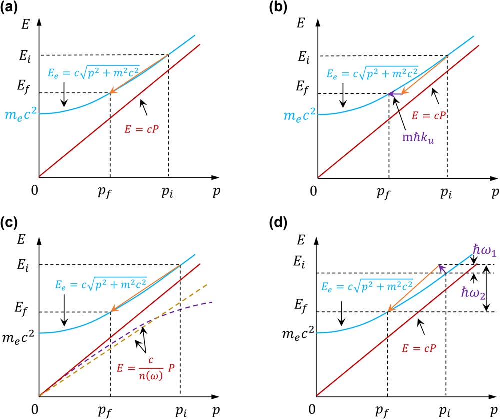
From wave–particle duality, the electron energy–momentum relation can be written as in the form of De Broglie wave , : where is the normalized electron speed by light speed . For a photon with energy and momentum in vacuum, it has the dispersion relation where , is the wave vector of the corresponding photon, and is Planck’s constant. By putting together the dispersion relation of the wave and the electron on the same diagram [Fig. 1(a)], it is clear that the interaction is forbidden between electrons and photons in vacuum without an external field, as the slope , and the conservation of energy and momentum cannot be simultaneously satisfied. Here, () and () represent the initial and final states of the electron; and k represent the frequency and wavevector of the light field, respectively. As a result, to obey energy–momentum conservation, the slope of the electron needs to be increased; otherwise, tilt the dispersion of the photon towards the momentum axis, i.e., decrease the phase velocity of light.
Figure 1.The blue solid line represents the electron dispersion curve, while the red dashed line represents the electromagnetic wave dispersion curve. () and () represent initial state and final state, respectively. (a) Dispersion relation of a free electron and electromagnetic wave in vacuum; the electromagnetic wave dispersion curve is an asymptote of the electron. (b) Interaction between free electrons and electromagnetic waves in a periodic static magnet environment. (c) Interaction between free electrons and electromagnetic waves in slow-wave structures. Phase velocity of electromagnetic wave is smaller than . The purple and yellow dashed lines represent the electromagnetic field dispersion curves on a homogeneous medium and hyperbolic dispersive medium, respectively. (d) Compton scattering of a free electron with an electromagnetic field, in which the electron absorbs a photon and emits a high-energy photon.
Specifically, the first method is to modify the state of electrons. A periodic static magnetic field can provide quanta of momentum mℏ︀2π/λu (or mℏ︀ku) necessary to satisfy the conservation law. This way, the energy conservation law remains unchanged, while the momentum is modified by periodic magnetic field modulation[41], where ku is wavevector of periodic magnetic fields, and . It indicates that the field serves as a momentum reservoir which provides a transverse velocity for electrons to modify the axial momentum, as shown in Fig. 1(b). This configuration is employed in the undulator and further developed FEL facilities. Another scheme is also called a slow-wave configuration. By introducing dielectrics, waveguide structures, grating structures, etc., the phase velocity of the light field is smaller than the speed of light: , where is the refractive index. Hence, the light field can exhibit different dispersion curves according to the specific materials or geometrical structures, as shown in Fig. 1(c). The dispersion relation of the electron remains unchanged in this case. Apart from the static magnetic field and the slow-wave structure, electromagnetic field can also provide necessary phase matching for electron–photon interactions. Indeed, in an inverse Compton scattering process, a photon interacts head-on with an electron and scatters a high-energy photon. This is equivalent to modulating the electrons with both energy and momentum:Here, the energy and momentum of the electron are simultaneously modified to satisfy the dispersion curve of the photon in free space, as shown in Fig. 1(d).
Once the phase matching condition is satisfied (i.e., the energy-momentum relationship mentioned above) and the electrons are in the appropriate phase, then the free electrons undergo deceleration or transverse velocity modulation, resulting in photon radiation emission[42].
2.1 Description of Free-Electron Fundamental Radiation
The absorption and emission of photons by free electrons are the most important aspects of interactions between light and free electrons. When the electron velocity is synchronized with the phase velocity of the light field (i.e., phase-matching , where is the electron velocity, is the photon frequency, and is its wave vector), efficient energy exchange occurs with the net energy gain or loss of an electron determined by the phase of the light field in which the electron is placed. Theoretically, whether the electron or light field gains net energy can be classified into three scenarios. First, a portion of the free electrons loses energy, whereas the remainder acquires energy, resulting in no change in the interacting light field. Second, the energy gain exceeds the energy loss of free electrons, resulting in a decrease in the light field. Third, free electrons lose energy and emit photons.
Because the coherent radiation of free electrons has a wide range of applications, this section introduces the fundamentals of relativistic electron radiation and provides analytical results for the key general factors that govern radiation quality.
The features of FEL radiation are determined by the relativistic free-electron state of motion, and the quality of the relativistic free electrons also controls the process of stimulated radiation. Therefore, this radiation is closely related to the charges and trajectories of relativistic free electrons. Next, we introduce an electron with charge and mass at position , which can give rise to the electron density and current density: which obey the continuity equation , where , and can be decomposed into its longitudinal and transverse parts and . The current density in the frequency domain is expressed as
In an inertial reference frame, the electromagnetic field generated by the motion of the charge , position , and velocity can be described using the basic Lienard–Wiechert scalar and vector potentials. The electromagnetic field corresponding to the moving charge can be expressed as[43]
The electromagnetic field of a moving point charge can be decomposed into two parts: the velocity field (or self-field) and acceleration field (or radiation field). Whereas the velocity field is related to the velocity of the point charge, the acceleration field is related to its acceleration . The velocity field varies as and cannot radiate to the far field, whereas the radiation field varies as and can radiate energy to the far field. Equations (11) and (12) can be used to derive radiation produced by the moving free electrons, which is given by the Larmor formula of classical electrodynamics: where and are the electronic mass and momentum, respectively. From the Lorentz invariance, Eq. (13) can be rewritten as where , and is the electron four-momentum vector. Then,
We use the electron velocity and acceleration to expand and ; is the electron rest energy. We then obtain the Lienard equation where is the normalized electron energy. The radiation energy is given by[44]
Equation (17) represents the energy radiated by a free electron in a solid angle with the observation direction of n centered on in a frequency bandwidth , is the position of the electron at time , is the normalized velocity of the electron, is the normalized acceleration of the electron, is the speed of light, and is the electron charge. In Eq. (17), is the phase distribution of the angular frequency, which is approximated as . Considering that the integrand is non-zero, the frequency of the free-electron oscillation is close to when the frequency of the radiation light field is . This indicates that there is a Doppler shift in the frequency, which is related to free-electron energy , so that it is possible for free electrons to produce shortwave radiation. In the denominator of the integral in Eq. (13), let be the angle between and . Then for small angles, this can be expressed as . It can be shown that when , , and when the radiated power is highest. In this case, the radiation will be along the direction of the velocity, which means that in the rest coordinate system, the electron emits isotropic radiation and the angle of divergence in the laboratory coordinate system is . The term in the integrand of Eq. (17) denotes the two forces acting on the electron including the transverse force and longitudinal force , resulting in the two perpendicular accelerations. It indicates that when the free-electron energy is greater than the electron rest energy, i.e., , is more significant in the radiated energy, which is proportional to the square of the acceleration , where is the radiation power, and is the transverse force on the electrons[45]. In contrast, when the electron energy is lower than the rest energy, i.e., , at which point the contribution to the radiated power of the free electron is equal regardless of the axial radial acceleration. As a result, deflection modulation of the transverse field or deceleration modulation of the longitudinal field becomes vital to keV–MeV electrons’ coherent radiation in modulating the free-electron radiation, especially for the compact coherent electron radiation sources described in Sections 3 and 4. Whichever of these forces is exerted on the electrons, the radiation efficiency will increase. In addition, based on Eq. (17), when , the electron does not emit any radiation. This implies that the acceleration obtained by the free electron in its trajectory is the decisive factor leading to the emission of electromagnetic waves by the charged particles. Therefore, to obtain high radiation energy, the transverse force generated by the action on the electron is more effective than the longitudinal force.
2.2 Different Types of Free-Electron Radiation
Free-electron radiation research dates back to the 18th century. We can divide the conditions under which free-electron radiation occurs into two categories: (1) radiation generated by the direct interaction of free electrons with matter, which is more representative of cathodic fluorescence, CR, and transition radiation, and (2) far-field radiation generated when the acceleration of free electrons is altered by the modulation of an external electromagnetic field. Representative examples of the latter type of radiation include synchrotron radiation, Smith–Purcell radiation, undulator radiation, and Compton scattering.
CL, also known as electron scintillation, occurs when an electron beam bombards a substance. Typically, it is found in materials with radiative energy levels, such as semiconductors and defect-doped media. The free electrons that strike the material can transfer a portion of their energy into the energy band, make secondary electron leaps, or activate bandgap structures and stimulate the creation of radiation. For instance, the electron impact on a semiconductor following electron loss energy transfer to the electron–hole pair causes its excitation or loss of energy to the excited impurity state. Because secondary electrons are generated in this process, it is typically defined as incoherent radiation, which is the light emission from this non-equilibrium steady-state distribution.
CR as shown in Fig. 2(a) is the spontaneous radiation produced by the motion of free electrons in a homogenous dielectric medium, whose velocity exceeds the phase velocity of light in the medium. In 1934, the Soviet physicist P. A. Cherenkov experimentally discovered this phenomenon[46]. In 1958, P. A. Cherenkov, I. M. Frank, and I. Y. Tamm were awarded the Nobel Prize for discovering and physically understanding the effects of CR. When the condition is satisfied, the transverse direction of electron motion has a real wave vector component , where is the electron wave vector, is the refractive index of the homogeneous medium, and is the dielectric constant of the medium. The dispersion relation is given by . From the conservation of momentum and energy, the CR angle can be estimated as . The number of photons emitted as a function of the wavelength is given by
The spectral density of the CR per unit propagation length is described by the classic Frank–Tamm formula[18,47]where is the Heaviside step function [when , then ; otherwise, ]. In addition, the Heaviside function defines the Cherenkov threshold as . CR is utilized in numerous domains including the detection of high-energy particles[4,48–50], nonlinear optics[51–53], dose diagnosis, and medicine[54]. In addition, CR has been widely employed in other domains, including cosmic rays, the detection of energetic particles in the universe, nuclear physics, geophysics, and cosmology.
Transition radiation, shown in Fig. 2(b), is the radiation generated at the boundary between two media with different dielectric constants by a moving charged particle, where there is an abrupt change in the electromagnetic field (e.g., when a high-energy electron enters a material from a vacuum). As far-field radiation, transition radiation can be intuitively understood as the difference between the electromagnetic field wave vectors produced by electrons in two discontinuous media. Depending on the energy of the incident electrons and the dielectric response function at the dielectric boundary, the spectrum of transverse radiation is often broad and extends from IR to UV, and even X-rays. The free electrons in vacuum that strike a perfect conductor with positive incidence are viewed as two electrons with a relative velocity that collide at the boundary, causing the free electrons to decelerate simultaneously. Ginzburg’s original formula for calculating the spectral distribution of the crossing radiation can be written as[55]
Recent experimental studies have studied the generation of a strong THz SPP on a wire waveguide by means of a coherent transition radiation process using a 3 MeV electron impinging on a metal tip[56] as well as the dispersion relation of the THz SPP[57,58].
The coherent synchrotron radiation shown in Fig. 2(c) is a collective effect of free-electron radiation, which mostly arises when the trajectory of an electron beam is curved in a dipole magnet. Because the particle paths in most accelerators are deflected by a magnetic field, synchrotron radiation is also known as magnetic bremsstrahlung radiation. Depending on the intensity of the magnetic field and electron energy emitted, the light spectrum can range from the microwave to X-ray region. Assuming that the path of the free electrons in the bending magnet is circular, we can derive the radiation per unit steric angle and radiation power per unit frequency using the following equation[59]:
In 1988, Professor Paul Hartman of Cornell University (Cornell University had conducted experimental research in the area of synchrotron radiation) delivered the first talk at a symposium on the early development of synchrotron radiation[60]. In 1947, during the commissioning phase of a 70 MeV electron synchrotron constructed at the General Electric Company Laboratory (GE lab) in Schenectady, New York, United States, the first historical observation of synchrotron radiation was made. There are two primary types of synchrotron radiation facilities: storage ring-based sources and linear-accelerator-based sources. More than 50 synchrotron radiation sources are now operational in 23 countries around the world. In the 1990s, the European synchrotron radiation device (ESRF), U.S. Advanced Photon Source (APS), Japan’s Super Photon Ring-8 (SPring-8), and other third-generation synchrotron radiation sources with electron emission degrees of approximately 3 nm rad remained the backbone of synchrotron radiation facilities, demonstrating the durability of such large light-source devices. Modern technology has advanced to third-generation synchrotron radiation light-source devices, such as the U.S.-based Stanford Synchrotron Radiation Light Source (SSRL), Germany’s DESY-PETRA III, ESRF, Italy’s synchrotron radiation facility (Elettra), China’s Shanghai Synchrotron Radiation Facility (SSRF), and Japan’s SPring-8. The 3.5 GeV SSRF, constructed in 2009, is a medium-energy third-generation synchrotron radiation facility with 16 beamlines in operation, with 16 new beamlines and experimental auxiliary systems added in 2016. It is the driving force behind China’s advanced light sources and is widely used in X-ray diffraction, scattering, spectral diagnosis, and X-ray imaging.
The Smith–Purcell radiation (SPR) shown in Fig. 2(d)[61] is far-field radiation released by charged particles traveling close to the grating structure’s surface. This radiation phenomenon was first discovered by two American physicists, Smith and Purcell, in 1953[3]. The wavelength of SPR is determined by the velocity of free electrons and the geometry of the periodic structure. As a light source that can be tuned, SPR can generate microwave to X-ray frequencies. The SPR effect has been investigated extensively[62,63] and utilized extensively in investigations of particle identification[64,65], particle acceleration[66], and free-electron stimulated radiation[67], among other applications. Similar to CR, SPR is the spontaneous emission of CR as Bloch photons in a periodic medium. When the phase-matching condition is satisfied, electron radiation can be coupled to Bloch photons, where is the free electron velocity, is the Bloch wave vector in the first Brillouin zone, and is the inverse lattice vector. SPR is produced when the harmonics of the wave vector are diffracted into the far field. The frequency of the emitted photons is dependent on the free electron velocity and the periodic structure of the photonic crystal (spatial period of the grating), which is expressed as . Today, the progress in nanotechnology has significantly contributed to the advancement of SPR research, whose ultimate goal is to achieve integrated on-chip light sources by minimizing free-electron energy and photonic structural space[68–70]. Thus far, SPR has developed from near-UV[71] to X-rays[72]. With advancements in micro- and nanotechnologies, such as photolithography, electron beam exposure, and ion beam etching, grating structures with reduced spatial dimensions can be manufactured[73–76], thereby permitting SPR radiation on some nonperiodic structures[77]. Electron beam emissions generated by field emitters/integrated all-silicon structure circuits have been reported in several studies[78,79]. It is anticipated that SPR produced in photonic crystals of the same periodic material will result in an increase in radiated power[80]. It was also discovered that the analogous spatial period of photonic crystals is on the sub-nanometer scale, and that these qualities permit the emission of UV or X-rays by electrons with low energies[81–84].
2.3 Self-Amplified Spontaneous Emission
An FEL is one such source, and because of the Doppler frequency upconversion of relativistic electron radiation, this mechanism is ideally suited for producing short-wavelength X-rays. In FEL operation, the wavelength of the radiation is proportional to the square of the electron’s energy . The upconversion of the Doppler frequency renders this mechanism ideal for producing X-rays of short wavelengths, since no other light pulses are of such short durations and high energies. Madey et al.[85] introduced the initial FEL concept in 1971 and proposed two experimental configurations for the development of FELs: an FEL oscillator and an FEL amplifier[22]. An FEL is a combination of physics and technology of particle accelerators and lasers, and usually consists basically of an electron accelerator and an undulator magnet. The coupling of electromagnetic radiation and free electrons is necessary to activate free-electron amplification in an FEL amplifier. Otherwise, in the absence of such radiation, free-electron radiation amplification can be triggered by self-generated incoherent spontaneous radiation or background noise in a so-called self-amplified spontaneous emission (SASE) FEL. SASE FEL is one of the simplest and intuitive configurations for realizing FEL. Apart from the SASE FEL, the recently developed high-gain FELs can produce higher energy output at higher frequencies using premodulated microbunching free electrons, triggered by an external seed laser pulse. This mode of operation is known as seeded FEL and permits the generation of harmonics at the oscillation frequency of electrons. Consequently, the emitted radiation is completely coherent because its properties are determined by the seed laser pulse—exactly why it has recently become more and more favored. Thus, SASE FEL is the most compact and direct method for achieving FEL in the seed-triggered free-electron stimulated radiation process.
Given that free electron lasers rely on relativistic free electrons, FEL facilities are typically constructed near the storage rings of synchrotron light sources or radiofrequency (RF) linear accelerators. The radiation modulator is the central component of FEL, where the most common devices can be classified into “undulators” and “wigglers” as shown in Fig. 2(e). Because an undulator consists of a periodic array of a large number of extremely powerful dipole magnets as compared to a secondary bent iron in coherent synchrotron radiation, it results in greater X-ray energy and electron radiation flux. In addition, the structure of the undulator resembles that of a wiggler, however, with smaller magnetic field amplitude and weaker transverse modulation of free electrons. Consequently, in comparison with wigglers, undulators provide improved collimation and coherence of light, which results in a frequency upconversion squared by Lorentz factor and radiation in the X-ray range with an intrinsically narrowband and harmonic output. Essentially, despite the distinct working modes of the two magnetic field forms, they may be reconciled by the same resonance equation; hence, we will now discuss undulator radiation.
For the SASE FEL process, since the initial electron beam pulse length is much longer than the radiation wavelength, the distribution of electrons can be considered homogeneous and spans multiple optical cycles. As a result, electrons in the radiation field experience both acceleration and deceleration, giving rise to the random absorption/emission of the photons of the radiation field. Spontaneous radiation arises from the stochastic noise fluctuation of this process. After several interaction cycles, electrons in different phases undergo different energy modulations. The energy modulation is then transformed into density modulation, which ultimately leads to the bunching of electrons. As such, the stochastic spontaneous radiation ends up with stimulated radiation due to the bunching process, which transforms the electron pulse to be smaller than the radiation wavelength. Thus, the SASE process is originated from stochastic spontaneous radiation and is therefore inherently partially coherent. For this reason, the radiant energy of SASE FEL is regarded somewhere between spontaneous radiation and stimulated superradiation.
To further optimize the FEL radiation coherence and radiant energy, some groups have proposed the seeded FEL by pre-bunching free electrons (i.e., microbunching) before injecting them to the undulator, where the external input coherent laser as a seed in direct interaction with the pre-bunching electrons leads to high-gain mode. Currently, three approaches have been proposed: high-gain harmonic generation (HGHG)[86–88], echo-enabled harmonic generation (EEHG)[89,90], and phase-merging enhanced harmonic generation (PEHG)[91,92]. The modulator segment pre-bunches the free electrons into an ultrashort beam, resulting in direct high gain and high-harmonic radiation mode in the second-stage undulator. This seeded FEL setup accomplishes radiative harmonic production while retaining the excellent coherence of the seed light. As a result, this flexible approach, which can independently adjust the microbunching modulation of free electrons, has now become the standard FEL scheme.
The basic FEL mechanism is described below to qualitatively investigate the radiation wavelength and resonance relationship of the FEL. We can consider a moving free-electron pulse as a current source. The stimulated radiation of the current source was investigated when modulated by a periodic transverse force in an undulator. The current source trajectory can be modeled as a simple transverse sinusoidal oscillation with a constant period and constant velocity : where is the wave vector, is the amplitude, and is the maximum angle between the electron velocity and the longitudinal unit vector as shown in Fig. 3(b). The undulator parameter is a fundamental dimensionless parameter, which can be written in experiment as for the static magnetic field B0 and period u. Also, it represents the normalized undulator vector potential amplitude and plays an important role in FEL theory. Therefore, by applying the gradient operation to Eq. (22), the longitudinal velocity component is obtained as
Figure 3.(a) Schematic diagram of undulator radiation in the SASE regime. Due to the random electrons at the entrance of the undulator, incoherent radiation is emitted, and subsequently the electron beam undergoes density modulation to achieve microbunching on the radiation wavelength scale. With increased coherence, the radiated power along the undulator eventually achieves exponential gain amplification. (b) Illustration of the free-electron trajectory in an undulator and the instantaneously emitted radiation. represents the maximum angle between the electron velocity and the propagation axis, represents the opening angle of the radiation cone, while represents the spatial period of the radiation emitted in the direction of the observation angle .
The radiation of electrons subjected to continuous Lorentz forces is also periodic. When the radiation emitted by a free electron in a given cycle resonates with that emitted in the previous cycle, it is referred to as coherent radiation. As seen in Fig. 3(b), the initial position of the electron is (at ), the undulator spatial period is , and the period of the electron trajectory is , where the electron is in a periodic phase ( and ) with the same amplitude (). Coherent enhancement of the radiation produced by electrons at and requires the corresponding optical path to be separated by an integer multiple of the wavelength: . Thus, we can obtain the undulator radiation resonance relation
Equation (25) represents the classical radiation spectrum of an undulator, which must indicate the fundamental frequency . In addition, a general formation, including its harmonics, can be composed by considering axial radiation[20]: where is the harmonic number of the radiation. A more detailed theoretical analysis[93] shows that only odd-harmonic wavelengths of radiation, that is, , are strongly emitted along the axis.
Coherent interaction takes place between the radiation field and amplification of stimulated radiation due to the free electrons under suitable phase-matching conditions, with an external radiation field serving as the seed and free electrons as the gain medium. The spectrum, polarization, and phase of the photon modes produced by the free electrons are compatible with the modulated light field.
Furthermore, new concepts for plasma acceleration and optical undulators have emerged, facilitated by the development of free-electron physics and ultra-intense lasers. This research area is particularly attractive since it can provide compact light sources with controllable polarization, tunable radiation spectrum, and high photon brightness in an ultrafast manner. Simultaneously, an innovative compact radiation light source was investigated using free-electron radiation based on nanophotonics. In this approach, the geometric structure of the materials is used to control and boost the photon emission mode by utilizing the unique electromagnetic response qualities of 3D and 2D materials. Alternatively, a laser-like mode can be formed by modulating and producing coherent stimulated radiation using new photon modes (for example, SPP, surface phonon–polariton, exciton, or other quasi-particle free electron radiation modes). In an FEL, the free electrons and their radiation propagate along the longitudinal axis of an undulator in the same direction. The interaction in FEL is essentially a positive-feedback mechanism. The free electrons in the undulator are subjected to a transverse force to produce radiation, where this radiation modifies the position (phase) of the free electrons so that they continue to emit radiation, eventually resulting in coherent emission. This interaction mechanism is at the core of modern X-ray FEL technologies and designs.
3 Compact Free-Electron-Driven Radiation Sources
In recent years, scientists have pursued miniaturization of FELs, especially for X-band FELs, which have wide applications in various fields. Based on the laser wavelength radiation theory described in Section 2, there are two physical quantities that determine the characteristics of radiation: one is the relativistic electron energy and the other is the undulator period . According to Eq. (26), there are two main experimental means towards miniaturization that are expected to be realized. With the development of ultra-intense ultrashort lasers, the integration of the accelerator and undulator with these lasers makes miniaturization of the FEL possible, and it is from these two key physical quantities that the LWFA is developed. A recent increase in the quality of electrons obtained by LWFA is one of the promising ways. The most anticipated application for the maturation of laser plasma electrons is the replacement of kilometer-long acceleration devices to obtain high-quality, high-energy electron beams at shorter distances. LWFA high-quality free electrons now show strong potential as electron sources, on which several international groups have conducted experimental verifications and demonstrations.
Scientists have been working on the downsizing of FEL in recent years, particularly the commonly utilized X-ray FEL systems. According to the laser wavelength radiation theory presented in Section 2, there are two main technological avenues for miniaturization. Specifically, according to Eq. (26), the wavelength of FEL light is primarily influenced by two physical parameters: the period and the relativistic energy of the free electron. On one hand, the application of the laser wakefield with rapid advancements in ultra-intense and ultrashort lasers allows for the miniaturization of the acceleration stage of electrons from the kilometer to a few meters scale. LWFA is distinguished by an acceleration gradient of up to 100 GV/m in a plasma bubble[94]. The first experimental demonstration of LWFA-based FEL in the 27 nm extreme UV (EUV) band was made possible by recent improvements in the quality of electrons collected using LWFA[95]. These electron beams have kinetic energy of approximately 500 MeV, charge of tens of pico-Coulombs, and an energy spread as low as 5‰. The associated FEL parameter is estimated to be of the order of 0.1%, presenting a substantial obstacle to the realization of a high-gain FEL, although conventional X-ray FEL(XFEL) devices require an electronic energy dissipation of 0.01%–0.1%[96–98]. Consequently, multiple research organizations worldwide are focusing on the experimental improvement of LWFA-based compact FELs, particularly in terms of the LWFA’s stability and their capacity to reach shorter radiation wavelengths.
On the other hand, the shortening of the undulator period of free-electron transverse modulation provides a distinct means of circumventing the large energy required by conventional undulators. Commonly utilized undulators are designed with a periodic magnetic field on the centimeter scale. With this technique, hundreds of cycles are often required to attain stimulated radiation production; therefore, the volume and cost of the entire device are extremely high. The cost and size of FEL can be significantly reduced by decreasing the spatial periodic size of the undulator, enabling a completely new field for modulating free electrons with a laser light field. According to Eq. (22), decreasing the undulator period reduces the electron energy required while maintaining the same radiation wavelength . This permits a reduction in the size of both the accelerator and undulator. During the past two decades, numerous experimental advancements have been made towards this goal. For example, micro undulators have been proposed to generate electron radiation by confining a strong localized near field on the surface of a material or by modulating free electrons using a strong laser field directly in free space[24,26,99–102]. According to the scaling law, if the oscillation period of the undulator is shortened by a factor of , then the corresponding free electron energy requirement is also scaled down according to . Hence, this idea is expected to further reduce the volume of free-electron coherent light sources.
The development of electronic acceleration technology and novel light-field-modulated electronic radiation has enabled the miniaturization of FELs. By concentrating on the rare and more valuable X-ray band by the stimulated radiation of free electrons, this section will primarily introduce the most current research results on the downsizing of FELs from these two perspectives, and examine the necessary directions for future development.
3.1 Compact FEL Driven by Laser Plasma Accelerator
Owing to the limited acceleration field supplied by the RF waveband, the production of relativistic particle energies requires the use of massive and expensive devices. This has prompted the rapid growth of the research field LWFA. In 1979, LWFA was initially presented by Tajima and Dawson[94]. In 2004, three experimental groups from the Imperial College (UK)[103], Lawrence Berkeley National Laboratory (USA)[104], and Laboratoire d’Optique Appliquée (France)[105] obtained quasi-mono-energy electron beams based on LWFA, which pushed the laser plasma electron acceleration closer to reality.
Since then, a series of experiments have verified the fundamental ideas and innovative approaches for laser plasma acceleration and electron injection. These advancements are regarded as providing the possibility of manufacturing high-brightness electron beams that exhibit low emittance[106], short time (fs), and high peak current intensity (kA)[107,108]. LWFA is theoretically capable of creating electron beams of competitive quality. However, the reliability and reproducibility of these methods pose significant challenges. This is primarily because each acceleration drives the plasma to build a new acceleration cavity, and even a slight laser or plasma fluctuation can induce unanticipated jitter in the performance of the electron beam. Use of highly statistical experimental methods[109] and integration of artificial intelligence algorithms with active feedback adjustment[110] are well suited to address the issue. In 2020, a team from Universitat Hamburg and Deutsches Elektronen Synchrotron (DESY)[111] achieved the first 24 h stable operation of a laser–plasma accelerator using statistical data to link laser and electronic parameters. In the same year, a research team from Imperial College London experimentally coupled the 6D variable Bayesian optimization of LWFA with an optimizer betatron radiation process to obtain outstanding results. These achievements paved the way for engagement feedback loops and active performance control in LWFA.
To date, in this area of research, the particular benefits of electron acceleration in the laser wakefield have primarily manifested in three characteristics. Miniaturization. The length of ultrashort laser devices rarely exceeds 10 m owing to the use of laser devices as the source of electron acceleration. This design can be adopted in several conventional laboratories.Extremely steep acceleration gradients. The LWFA gradient is three orders of magnitude (up to ) greater than that of the RF accelerator. This characteristic makes it a desirable candidate for driving small free-electron X-ray lasers.Acceleration distances of the order of centimeters. Owing to this super-high acceleration gradient, free electrons with GeV-level energies in the experiment require an acceleration distance of only a few millimeters to a few centimeters, which is thousands of times shorter than the same target electron acceleration distance achieved using a conventionally large and expensive RF accelerator.
A limitation of the application of LWFA technology in practical FEL applications is the stability and quality of the electron beams, which are still inferior to those of traditional RF accelerators. To efficiently produce radiation in an FEL, the electron beam must have high 6D brightness, which is defined as the ratio of the peak current of the electron beam core to the product of the root mean square (RMS) transverse normalized emittance and RMS fractional energy diffusion in units of 0.1%: where is the longitudinal charge density, are the normalized emittances in both directions, and is energy divergence.
To solve the previously mentioned difficulties in beam emittance and energy dispersion, several research groups have developed various methods, including a small cryogenically cooled undulator FEL experimental system based on high-gradient quadrupoles (permanent-magnet quadrupoles) with no strong focusing proposed by LAOLA, a collaborative team at the University of Hamburg and DESY[112]. In addition, to shorten the electron beam stream, the Bella Center at Lawrence Berkeley National Laboratory combines ultrahigh gradients in excess of active plasma lens[113] and a 4 m long intensely focused visible-infrared SASE amplifier (VISA) undulator. The high-energy electrons produced by the LWFA are managed in various ways to maximize their injection into the undulator during the excitation process, as described in the preceding section. A four-stage iron beam collimation system from a traditional acceleration field is the most effective method for collimating and selecting the energy of the LWFA.
Multiple international research groups have experimentally validated the FEL driven by LWFA, where nonlinear exponential gain to generate a stimulated radiation amplification output has been demonstrated. Wang et al.[95] from Shanghai Institute of Optics and Fine Mechanics, for example, used a 200 TW ultra-intense and ultrashort laser drive to obtain 490 MeV of energy, less than 0.5% of energy dispersion, about 30 pC of beam charge, and about 0.2 mrad of LWFA electron beam emitted by RMS, where the downstream magnets consisting of two quadruples are employed for energy selection, as shown in Fig. 4(a). Furthermore, the experimental validation of SASE FEL exponential amplification in the 27 nm wavelength region has set a precedent for the advancement of LWFA in practical FEL light-source applications.
Figure 4.(a) Wang et al. experimentally verified LWFA free-electron injection into a conventional static magnetic undulator to achieve SASE-FEL operation in the 27 nm EUV band to achieve exponential gain[95]. (b) SASE-FEL operation in the 830 nm IR band using a compact laser plasma accelerator[114]. (c) LWFA electron-source-driven SASE-FEL at 270 nm with excellent longitudinal coherence for high-gain coherent radiation and amplification at SOLEIL laboratory, France. (d) PWFA electron-source-driven X-ray FEL experimental design.
In 2021, Pompili et al.[114] from Laboratori Nazionali di Frascati, Italy, experimentally verified a compact FEL driven by a laser plasma wakefield accelerator (PWFA) free-electron beam, as shown in Fig. 4(b). The experiment was conducted at the SPARC LAB testing facility[115]. They used a cautious technique, feeding the electrons generated by a photocathode electron source into a centimeter-scale beam-driven PWFA for acceleration. In addition, two triplets of movable permanent magnet quadrupoles (PMQs) were used in this configuration to focus the beam onto the plasma and retrieve it following its acceleration into the undulator. Their measured high-energy electron beam current with a high-quality 6D phase space was comparable to that of state-of-the-art RF electron accelerators. The exponential gain of SASE in the 830 nm IR region was experimentally validated.
The above two compact LWFA-driven FEL systems are based on a SASE scheme, with radiation beginning with random-phase electron shot noise. Because spontaneous undulator radiation emissions are stochastic, the SASE FEL is chaotic and lacks longitudinal coherence (temporal coherence). Therefore, extensive attempts have been made to overcome these challenges by maximizing the effective bandwidth and improving radiation coherence, particularly temporal coherence. To date, several techniques have been developed to achieve this goal, with experimental techniques drawing on cutting-edge FELs such as HGHG[86,116], EEHG[90,117], and PEHG[91,92], which rely on high-quality and fully coherent external laser pulses as the available seed source. This seeded FEL approach accurately exploits the ultrashort temporal properties of LWFA electrons to perform optical-scale electron beam phase–space manipulation, resulting in microbunching at the harmonic wavelength of the seed laser. As a result, it can not only enter the exponential gain process swiftly but also preserve temporal coherence. Using this seeded FEL technique, it is theoretically possible to employ an electronic source to drive the LWFA process simultaneously. In 2022, a research team led by Marie Labat[118] from Synchrotron SOLEIL, France, confirmed that LWFA electron-driven seeded FELs may attain temporal coherence, as shown in Fig. 4(c). The LWFA stage is tuned for high-charge and low-divergence beams at peak energy with an energy spread (). Their configuration is similar to that of the HGHG FEL, where the beam is decompressed in the chicane and simultaneously injected into the undulator with a seed laser pulse. The radiation wavelength of the FEL was set at 270 nm using external seeds. Observing the phase-locked interference fringes between the seed pulse and the FEL pulse provided longitudinal coherence.
The three preceding investigations validated the realization of FEL in the EUV, IR, and UV bands utilizing the LWFA mechanism as an electron source-driven undulator. Furthermore, the current results indicate that enhancing the 6D brightness characteristics of the electron beam is required for LWFA electron sources driving shorter wavelengths, such as X-ray FEL. Because the 6D brightness characteristics are interdependent, it is vital to perform parallel processes and optimize the three key indicators of emittance, peak current, and energy dissipation during the initial LWFA step. A team led by Habib et al.[119] from the University of Strathclyde in England proposed a small attosecond-angstrom FEL concept based on the PWFA mechanism, as shown in Fig. 4(d). Using this method, they achieved unprecedented low emissivity and high brightness for sub-femtosecond duration electron beams within the emissivity at several nm rad levels. The overall device length in the planned testing setup was approximately 25 m. In contrast to LWFA, PWFAs are powered by powerful particle bunches such as relativistic electron beams and can maintain plasma wakefield. PWFAs have three distinct advantages over LWFAs in terms of the acceleration of high-quality electron beams. First, with a longer diffraction length, the plasma wakefield excited by free electrons can be guided to several meters by plasma focusing. Second, there will be no phase slippage, which is unavoidable in LWFA. Third, the technology for producing high-energy density electron beams with high average power is mature and efficient. However, the main disadvantages of PWFAs are their high repetition rate, long-term stability, and reproducibility[120]. Recently, a DESY group investigated the maximum limit of PWFA repetition rates at megahertz frequencies[121]. This finding suggests that PWFA and LWFA could be developed as realistic high-repetition-rate energy boosters for particle physics and photon science facilities, for both the present and future.
This acceleration mechanism has a far higher acceleration gradient than RF accelerators, making it the most promising next-generation particle acceleration technology. This plasma acceleration mechanism is based on the advantages of ultra-intense and ultrashort laser pulses, which provide an acceleration field thousands of times greater than that of conventional acceleration cavities. Hence, the electron beam energy required for X-ray FEL can be obtained within a few tens of centimeters of an accelerator, rather than a few kilometers. Laser plasma accelerators (LPAs) have led to considerable advances in the generation of FELs utilizing plasma-accelerated electron sources. However, numerous factors, such as the acceleration stage, beam transmission, and beam injection undulator, must be considered. The inherent energy dissipation and emissivity between the electrons in the LWFA mechanism constrain these crucial factors. Multiple research teams are currently working on developing conditions for steady and dependable electron-beam acceleration. Although the current LWFA performance does not match the performance of existing FEL systems that generate similar-wavelength radiation[88], its performance is considered comparable. Many challenges remain in LWFA-driven FEL implementation in X-ray bands. However, in the future, the stability, repetition rate, and efficiency of electron beam transfer to radiation may be enhanced. This development paves the way for ultracompact accelerator-driven FELs, which can be used to build free-electron light sources in small- to medium-sized facilities[122]. Usability is a requirement for a new tool that facilitates discovery and is anticipated to increase the global usability of FELs.
3.2 Micro Undulator Based on Surface Electromagnetic Fields
In addition to the aforementioned innovative mechanism for reducing electron accelerators and generating compact tabletop FEL light sources, miniaturization of the undulator is another attractive research area. In microscale structures, laser-driven surface electromagnetic modes or unique spatial electromagnetic modes on interfaces are efficient means of modulating free electrons. With the advancement of nanophotonics in recent years, emerging 2D materials and microfabricated structures have shown great capabilities to modulate the light field at the micro- and even nanoscale, which enables access to a desirable compact on-chip electronic coherent light source. Metal SPPs, graphene surface strong binding plasmon laser fields, and new atomic-level light fields of vdW[123,124] materials are good examples. These plasmon-, photon- or polaron-based “generalized undulators” can produce extremely high-photon-energy radiation without the use of highly relativistic electrons or high-intensity lasers. This innovative method of creating microscopic electromagnetic fields achieves a reduced spatial period compared to a typical periodic static magnetic field undulator, leading to the production of shortwave radiation for modulating electrons with energies ranging from keV to MeV. In other words, according to the radiation equation of the undulator, the electron energy can be scaled in tandem with the spatial period of the undulator. The relativistic free-electron energy is scaled down by a factor of 100 if undulator period is reduced by a factor of 10,000. In addition, the optical near-field enhancement effect permits the construction of a micro undulator with an increased equivalent modulation intensity and improved energy conversion efficiency. Importantly, this idea of an optical near-field nano to micro undulator is not specific to a particular material or mating surface design; rather, it is generated in a general sense by manipulating the dielectric response function () or a new micro–nano geometry design.
The ability of this near-field miniature optical undulator to drive the optical field directly to produce tunable control and optimized radiation properties by adjusting the optical frequency, material dielectric response function, and matesurface geometry is a significant advantage over conventional undulators.
In 2004, Andriyash et al.[99] proposed an experimental scheme for an ultrashort laser-driven nanoarray micro undulator, as shown in Fig. 5(a). In this experiment, an array of nanowires is placed perpendicular to the direction of laser propagation. When a laser pulse is incident on a nanowire, the nanowires are ionized by the laser field which, simultaneously produces a radial electric field. During this interaction, the relativistic electrons experience an initial modulation of the electrostatic field, resulting in the emission of radiation resembling undulator modulation. The electron transverse spatial period can be decreased to the point where the entire contact length is compressed to a very short length, because the matching undulator in this arrangement can be as small as a few micrometers. As a result, the photon energy can range from 12 keV to 106 keV, lowering the electron emittance requirement. Because the undulator inside the FEL facility is tens of meters long, the input electron beam emittance must be smaller than the radiation wavelength, , and the beam energy dispersion must be smaller than the FEL parameter, , where is the Pierce parameter[125,126], which gives a measure of the strength and scaling of the electron–radiation FEL coupling and its saturated efficiency; is the plasma frequency of the electron beam, ; and are the frequency and wave vector of the undulator, respectively. Furthermore, a shorter interaction distance reduces the need for electron emittance, allowing an electron beam stream with a divergence angle of milliradians to optimize its larger electron flux prior to natural divergence.
Figure 5.(a) Electric-field-driven micrometer-scale optical undulator fabricated from nanowire arrays excited by ultrashort laser pulses[99]. (b) Femtosecond-laser-driven wire-guided helical undulator for intense terahertz radiation generation[24]. (c) Subwavelength SPPs on a graphene layer serve as the optical undulator, which can modulate the free electrons to emit X-rays even with low-energy electrons[100]. (d) SPP undulator based on multilayer graphene, which could significantly increase the brightness of photons emitted by the undulator[101]. (e) Photon–polariton pair emission in a second-order two-quantum (spontaneous) emission process using a nanophotonic-structure-based undulator[26]. (f) Mating surface paired with graphene in an SPP undulator for producing harmonic emissions[102].
In 2016, Wong et al. proposed the use of graphene as a micro undulator platform to generate EUV to X-ray radiation, as shown in Fig. 5(c)[100]. Graphene plasmons are materials with well-studied optical properties and are characterized by their enhanced local density of states in the light field, strong-field confinement, and local-field enhancement. These features make graphene of great interest for optical applications. The periodic electromagnetic field of the subwavelength spatial period supplied by the graphene surface functions similarly to an ultrashort-period undulator. This allows electron beams with far less energy to generate shortwave radiation, such as X-rays[127]. In addition to the light generated by tuning the electron beam energy and plasma wavelength, graphene can be tuned by adjusting the Fermi energy level[128,129]. To boost the luminosity of X-rays, in 2019, Pizzi et al.[101] proposed multilayer graphene metamaterials, as a micro undulator technique for enhancing the electron–plasmonics interaction area, as shown in Fig. 5(d). Consequently, the output radiation intensity was up to 580 times greater than that of single-layer graphene. Theoretical simulations indicate that a high-energy photon output of 2.7–12 keV can be achieved by utilizing 5 MeV electrons in a graphene array micro undulator mechanism. Recently, it was confirmed that a carrier-excited optical near field functions as an optical undulator to control electron-generated radiation[130]. In addition to SPPs, electromagnetic vacuum fluctuations at IR and visible frequencies near and within the photonic crystal structures can be regarded as micro undulators, as shown in Figs. 5(e) and 5(f).
In 2019, Rivera et al.[131] presented photon–polaron two-quantum (spontaneous) emission processes. They theoretically demonstrated that this type of radiative emission can be used to control light emission at extremely high frequencies, such as X-rays. A nontrivial optical response in the polariton mode coincides with a significant connection between the polarization of light and the material. Therefore, the surface electrons were affected by the electromagnetic field fluctuations induced by the quantum fluctuations of the polarization current within the material. Although the expected value of this fluctuation field is zero, its variance is also zero, which may result in photon emissions in a distant field. In this study, the authors also claim that nanostructures or materials with resonances associated with plasmons, phonons, excitons, or magnon–polaritons enable robust coupling between electrons and polaritons. Therefore, it can be generalized to the concept of an optical micro undulator. The statement is supported by the dominant formula for frequency conversion of its radiation:
When free electrons carry high energy () and receive radiated photons in the axial direction (), . Multiplying the numerator and denominator by , at , , we have where is the frequency of the emitted photon, is the frequency of the emitted polariton, is the angle between the direction of the emitted photon and that of the electron, and is the angle between the polariton wave vector and that of the electron. Equation (29) suggests two methods for dramatically increasing the photon frequency. The first is to increase the energy of the electron, and the second is to use a structure that allows polariton modes with high wave vectors and effective mode indices simultaneously.
An exponential gain in the radiation power is desired to increase the photon luminosity of the micro undulator. In addition, the spontaneous radiation of free electrons must be transformed into stimulated radiation to attain higher coherence. This requires a strong connection between the free electrons and their radiation field, as well as a constant flow of energy between the radiation and stimulated processes. As a result, similar to a seeded FEL, the stimulated radiation of free electrons can be realized by injecting an external coherent radiation that matches the fundamental frequency or harmonic frequency of the micro undulator. In 2017, our group[132,133] developed a femtosecond-laser-driven wire-guided helical undulator for intense THz radiation, as shown in Fig. 5(b). In this mechanism, the free electrons are constrained by the charge separation field on the wire waveguide, and the motion of the electrons along the wire is governed by the relativistic Lorentz equation and the energy equations. The electron trajectories in the numerical simulation are shown in Fig. 5(b). The time width of guided electrons along the longitudinal forward direction is ps (picoseconds) scale. The frequency of SPPs radiated by free electrons is determined by their trajectory and energy as . Therefore, the motion state determines that the free-electron radiation frequency band of 100 keV is mainly located near the 0.30 THz band. In the far field, an ultrahigh energy-conversion efficiency of 1% was obtained for optical THz energy conversion, resulting from vacuum heating of a phase-locked electron source, which was produced in phase with the THz SPP seed source[134,135].
It should be noted that all conventional lasers operate according to the same fundamental principle: the stimulated radiation emission of photons (electromagnetic radiation). By injecting energy into a material known as a gain medium, the bound electrons in the medium can attain higher energy levels. Obviously, these higher-energy states can be “stimulated” by irradiating the gain medium with spontaneous emission corresponding to the same wavelength or triggered by other coherent radiation.
Photons can induce the emission of free electrons in the same manner as electrons in the atoms of the gain medium in traditional lasers. When a free electron passes through an electromagnetic field near the crest of an electromagnetic wave, it decelerates and releases energy that is transferred to the field with the same wavelength, direction, and polarization as that of the electromagnetic wave[136]. This modulation is the primary cause of free-electron-stimulated radiation in laser-stimulated photon emission.
These challenges were addressed by our group using a different approach (Fig. 6). Instead of using a high-energy electron source, the ultrashort electron pulse is driven by irradiating a micro meta wire with an IR pulse of 30 fs duration. This micro metal wire serves as a “waveguide” for guiding both THz SPPs and electron pulses, which has been well studied[58,133,137,138]. Ionization-generated electrons are accelerated by a large laser field[132,139] whose charge kinetic energy follows the scaling of the pump laser[140] and results in a high velocity (approximately ), where and respectively denote the laser intensity and wavelength, and is the vacuum speed of light.
Figure 6.(a) SPP generation and amplification processes, in which the femtosecond-laser-produced electron bunch coherently interacts with the weak seed field it spontaneously emitted in the first stage, resulting in SPP amplification. The color-coded map behind the SPP waveguide represents a close-up view of the SPPs. (b) Feynman diagram depicts the seed formation (stage I) and stimulated amplification (stage II) processes: a first-order spontaneous emission followed by a higher-order process in which the ultrashort bunch length can result in stimulated radiation emission within the instantaneous SPP field[36]. (c) Snapshot showing the electron pulse envelope (black solid line) inside the component of the THz SPPs. The red (blue) area of the field indicates the is in the positive (negative) direction. (d) Simulated electron phase dependence on the THz SPP field in a rest coordinate of the SPP field. It is noted that the space and phase variables in (a) and (b) can be used equivalently via , where is the wavelength of THz SPPs and is the phase velocity of the THz SPPs. The orange and blue sections of the curve represent, respectively, the deceleration/acceleration phase of the THz SPPs (a.u., arbitrary units).
In the experiment as shown in Fig. 6(a), coherent SPP amplification is achieved by passing an ultrashort free-electron pulse over a photonic structure that supports SPPs, such as metal wire, flat conductor surface, or the recently emerging vdW materials, including graphene. In a more basic physical model, as shown in the Feynman diagrams in Fig. 6(b), the SPP amplification process incorporates two stages: (I) seed creation, and (II) SPP amplification through electron–SPP energy exchanges. In stage I, SPPs can be excited either directly via free-space coupling with mode and momentum matched or by breaking the symmetry of charge translation on the surface, such as electron emission produced by femtosecond laser pulses. The initially excited SPPs were weak in terms of field strength for strong coupling effects. This structure–mode-matched polariton is henceforth referred to as the seed for the subsequent emission processes. When considering an electron pulse that is spatially-temporally shorter than the SPP seed and co-propagates with the seed field, stimulated superradiant radiation is produced as the co-propagating electrons are decelerated by the SPP field. This process underlies the coherent SPP amplification in stage II, in which the emitted photons reinforce the SPPs on the optical medium.
Essentially, the superradiant process is a high-gain FEL process, where the electrons interact with the optical field as a positive feedback process—the electrons emit radiation, which affects their position (phase) to emit radiation with higher coherence. In stimulated superradiant radiation, because the electrons are injected directly into the optimal phase of the radiation field, more efficient generation of coherent radiation than SASE FEL is allowed, and requires a much shorter undulator. Here, due to the pulse width of the electrons shorter than the SPPs’ wavelength, as shown in Figs. 6(c) and 6(d), the interaction of free electrons with SPPs is a superradiant process. Specifically, the width of the electron pulse in the experiment is 100 fs scale, while the SPP period is at the center frequency of 0.3 THz. It is noteworthy that the interaction process of SPP-modulated electron radiation occurs on the surface of the waveguide, which provides subwavelength confinement and field enhancement of the SPPs. Thus, the radiation emitted by free electrons can be viewed as scattering of virtual photons that couple to the waveguide and coherent superposition to amplify the SPPs energy. The strong SPP field would act on the free electrons as a stimulated process that constantly modulates the electrons to maintain energy exchanges. From the SPP energy evolution curves shown in Fig. 7, an exponential amplification of the SPP energy (green shaded area, from 0.32 ps to 1.73 ps) was found after an initial quasi-superradiant stage (0–0.32 ps). Eventually, the total SPP energy saturates gradually owing to the decrease in emitted polaritons.
Figure 7.SPP energy amplification by free-electron pumping at the waveguide surface presents a high-gain free-electron laser gain pattern, which undergoes superradiant radiation, exponential gain, and gain saturation owing to dephasing between electron and SPP wave packets.
In recent advances in coherent X-ray radiation in combination with FEL devices, the use of long-distance interaction and shorter pulse widths of electrons in this miniature undulator scheme can be extended to coherent X-ray radiation. We analyzed the microscopic dynamics of the interaction between electrons and THz SPPs, confirming the stimulated radiation with THz SPP. As shown in Figs. 6(c) and 6(d), the initial electron pulse is close to the zero-crossing of the longitudinal electric field of the THz SPPs, and most of the electrons are maintained in the deceleration phase as they move along the direction. This phase stability is caused by two distinct mechanisms: (1) THz SPP seed generation coincides with the swift electron emission process, and (2) a large quasi-static field is established on the wire surface[141,142], which always draws back the electrons, as shown in Fig. 6(c). Because the speed of the electrons is lower than the phase velocity of the THz SPPs, it gradually broadens and slips towards the tail of the half-cycle wave before it walks off. Consequently, the electrons remain in the deceleration phase during the interaction, leading to a net energy transfer from the electrons to the surface waves.
Our recent research demonstrated the energy exchange between free electrons and light fields, in which we separately deduced the radiation scaling and electron energy losses using a point-like electron source within the light field. Similar to the Rabi oscillation in a two-level system[143,144], an electron can successfully exchange energy with a light field if its phase is carefully controlled.
3.3 Radiation from Laser Plasma Undulator
The plasma cavity produced in LWFA can not only act as a co-propagated accelerator, but also serve as a wiggler or undulator. The transverse component of the electric field built into the plasma cavity exerts a modulation similar to that of the undulator radiation inside the plasma and produces highly collimated, high-photon energy, and ultrashort radiation. In general, when an intense laser propagates in a low-density plasma, its ponderomotive force drives the establishment of a large amplitude plasma wakefield, emptying the electrons in the plasma and generating an ion cavity known as the “plasma bubble” as shown in Fig. 8(a). In addition to the accelerated longitudinal field, this spherical plasma cavity has a very strong built-in transverse electric field throughout the LWFA process, as discussed in Section 3.1. When relativistic electrons pass through these fields, their transverse momentum is modulated at a particular frequency, causing free electrons to oscillate laterally while accelerating. This corresponds to the undulator radiation mentioned in Section 2.2 and can be directly compared with the synchrotron radiation in the undulator, known as betatron radiation. Rousse et al.[145] have experimentally demonstrated collimated X-ray synchrotron radiation emission up to keV energy by betatron radiation, which originates from acceleration and transverse oscillation of free electrons in plasma, as shown in Fig. 8(b). Because the oscillation period of plasma bubbles as undulators in laser–plasma interactions is substantially shorter than that of ordinary magnetostatic undulators, they can emit strong X-rays. Rousse et al.[145] and Kiselev et al.[146] hypothesized and demonstrated the feasibility of betatron radiation. Subsequently, brilliant collimated X-rays (keV) were measured experimentally[147–149]. Subsequently, Németh et al.[150] theoretically calculated microbunching of free electrons in a plasma undulator with a period approximately of a driving laser, which leads to coherent radiative emission. In this regard, obtaining higher emission power by increasing the interaction distance[151] and improving beam stability[152] as well as combining artificial intelligence[153] has been explored, as shown in Figs. 8(c) and 8(d).
Figure 8.(a) Schematic diagram of the betatron radiation driven by laser plasmonic bubbles. (b) Laser-driven plasma undulator that produces coherent synchrotron radiation. The laser plasma functions as both an accelerator and a wiggler[145]. (c) Simulation of controlling free electrons realizing micro bunching (red) in plasma wakefield (green)[150]. (d) Controlling the temporal laser pulse shapes in a bubble-enhanced betatron radiation system to achieve longer oscillation periods[151]. (e) Generation of X-rays with controllable polarization in the betatron regime. Using ionization-induced injection, the radiation-emitting orbits of relativistic electrons are controllable and reproducible with a lower divergence angle[152]. (f) Betatron radiation optimization through artificial Bayesian algorithm[153].
The betatron mechanism represents a significant advancement in the realm of plasma X-ray generators because it is the first optically driven plasma undulator radiation and serves as a reference for the possibility of undulator downsizing. The maximum electric field and radius of the cavity are[154]where denotes the plasma frequency. Hence, the electron trajectory in betatron radiation is analogous to that in undulator radiation, and parameters , remain therefore valid, with the corresponding local electron period and local strength parameter expressed as[45]
Here, the electron motion is assumed to be confined in a plane with a betatron amplitude of .
4 All-Optical Undulator Free-Electron Radiation
In addition to the FEL with a conventional undulator or micro undulator using a waveguide platform, periodic magnetic or surface light fields must rely on a specific medium or its surface to modulate the states of the electrons. In this way, the transverse electromagnetic field can be associated with its electric and magnetic field components in free space, such as Compton scattering mechanisms[155]. Intriguingly, this leaves a question of whether it is possible to employ a light field as an optical undulator in free space. Such undulators bypass the need for static magnets or media and have the advantages of shorter undulator period, rapidly adjustable polarization direction, no damage threshold limitation, large aperture, and high current strength.
ICS is a physical process in which free electrons in a laser beam are periodically modulated to release radiation. The process is comparable to that of a conventional undulator and can therefore be considered as an all-optical undulator that characterizes the high-energy photon radiation created by free electrons subjected to optical field modulation in a very powerful laser field. The ICS has physical characteristics essentially identical to the spontaneous coherent synchrotron radiation or undulator radiation found in large conventional synchrotron facilities. Because the laser wavelength is considerably shorter than the static periodic magnetic field of an undulator, the energy required for electron creation of hard X-rays is many orders of magnitude smaller than in big synchrotron facilities. Recent research has uncovered a number of compact synchrotron X-ray sources that utilize ICS and are room-sized. X-ray radiation is characterized by the physical parameters of the X-ray bandwidth, photon flux, source size, and divergence angle, which can be merged into a single quality factor, brightness:
Instead of static magnetic undulators, these recent research works use optical undulators that operate based on the principle of ICS. In addition, in ICS, if the free-electron pulse width satisfies the requirements of superradiant radiation, it can enter the stimulated radiation regime and ultimately produce coherent radiation, as described below.
4.1 Inverse Compton Scattering
First, we provide a brief explanation of the physical mechanism of ICS, which is the opposite of Compton scattering, as its name suggests. Here, the collision of electrons with photons results in the scattering of photons at higher energies. Formally, it is designated as . The interaction can be illustrated by schematic and Feynman diagrams, as shown in Fig. 9(a).
Figure 9.(a) Schematic representation of ICS. (b) Feynman diagram of ICS.
Assuming that a free electron with energy interacts with a photon with energy , the energy of the scattered photon by the ICS process can be expressed as follows[156]: where is the Lorentz factor for free electrons of kinetic energy , is electron mass, is the normalized vector potential of the laser pulse, is a nonlinear factor determined by the laser intensity, for the linear ICS process, is the fundamental photon energy, is the angle of incidence, is the scattering angle, and is the electron recoil parameter. If the , condition is met, then, by ignoring the quantum recoil effect[157], a simple form can be obtained as
The relationship between the photon energy of ICS and the energy of the colliding free electrons is consistent with that of the undulator radiation, which is proportional to . The scattered photon energy reaches its maximum when the backscattered photon collides in the direction of the electron beam.
Therefore, it is straightforward to present mathematical and theoretical explanations of the optical undulator nature of ICS. In the ICS process, the oscillating electromagnetic wave of the laser is equivalent to the alternating magnetic field in the undulator, because both the electric and magnetic fields are perpendicular to the electron’s direction of motion and orthogonal to each other. A mathematical explanation can be described as follows[158]. Assuming that the electron crosses an optical undulator with periodicity , the period of its motion will also be . Hence, , where represents the distance that the laser’s wave crest travels in the time interval (in the rest coordinate system of the electron), and the corresponding oscillation period is given by
Because the ICS process assumes a collision angle in opposite directions, the magnetic and electric fields would reinforce each other. The relationship between the electric field strength and magnetic field strength is , where is the speed of light in vacuum. So, the corresponding equivalent magnetic field can be written as
Thus, in the laboratory frame, the radiation wavelength is given by
The corresponding equation for the undulator radiation wavelength is given by where is the normalized amplitude of the laser, which can be interpreted as the undulator parameter , and is the electric field intensity of the laser. Therefore, if we replace the equivalent magnetic field with the magnetic field of the plane wave, and the equivalent undulator period with the wavelength of the plane wave, both parameters are identical to those of the undulator in the laboratory frame. The ICS equivalent undulator period is half of the colliding laser wavelength, i.e., , and the corresponding magnetic field intensity is twice the laser magnetic field strength.
The laser normalized amplitude can be compared with parameter . In this case, the laser field can be viewed as an undulator of free-electron radiation. The radiation wavelength in ICS is several orders of magnitude smaller than that in a conventional static magnetic undulator facility operating at the light wavelength scale. Consequently, high-energy electrons can enter the hard X-ray bands directly. In particular, the nonlinear ICS process happens when . This process usually involves multiple photons and thus can produce higher brightness, analogous to an optical wiggler when . Alternatively, electron energy can be released for the same wavelength of light. Therefore, the ICS is a technological method for generating miniature and compact free-electron light sources. This arrangement could be expanded to include optical undulators. In sectors such as nuclear fuel optical diagnosis, in situ imaging of nuclear materials, photonuclear physics research, and stacking imaging, gamma-ray light sources are now frequently employed for development[156,159–161].
The current ICS process, however, has not reached the superradiant regime because the pulse duration of the free electron corresponding to superradiant radiation in the optical band (about 100 attoseconds scale) is yet challenging. The following section will discuss conditions and recent efforts towards the superradiant optical undulator.
4.2 Superradiant Radiation of Electrons
Let us start with electron radiation in an undulator as an example. In general, the incoherent and coherent radiation of free electrons in quasiperiodic motion can be described as the unified radiation energy given by where is the relative phase of one emitted radiation electron with an electric field strength , and represents the total electron number of an electron pulse. Usually, . Hence, the total power of incoherent radiation and coherent radiation of electrons can be accessed according to Eq. (41). Specifically, the first term represents the incoherent radiation through a random superposition from electrons without phase correlation. The outcome is a random phase distribution of the radiation field of a single free electron within the pulse envelope, with the overall radiation intensity , proportional to . The second term is extremely sensitive to the phase connection between two electrons, and hence has no significance during the random phase-down period. To reach stimulated radiation to realize higher-energy radiation, the phases of all electrons must be strongly correlated, as . That is, once the free electrons realize microbunching, electron pulse length is less than the wavelength of the radiation , and the phase of each electron is nearly fixed with a high degree of correlation. Consequently, the radiation emitted by each electron is correlated too, resulting in coherent radiation. At this point, the overall power of the radiation equals the power of a single particle multiplied by . Therefore, it is possible to efficiently extract energy from pre-bunched electrons that matches well with the coherent radiation wave at the appropriate 6D volume in Liouville’s phase space. This operating model is worth receiving particular attention.
In 2019, Gover et al.[136] systematically introduced the stimulated superradiant radiation of bunched electron beams. Through stimulated superradiance in the presence of a seed-injected radiation field, the coherent emission brightness of bunched electron beams can be further improved. In particular, for undulator (wiggler) radiation and new free-electron modulation methods, both spontaneous and stimulated free-electron emissions are possible, if the free electrons are pre-modulated by microbunching. So as mentioned above, the most promising superiorities based on bunched electron stimulated superradiant radiation should be miniaturized, high-brightness, and high-coherence light sources. Thus, the injection of pre-bunched free electrons into the external coherent light field converts the spontaneous emission into stimulated radiation emission. To realize superradiant radiation in coherent spontaneous emission or stimulated radiation emission, free electron pulse widths must satisfy the condition[136]where is the radiation emission frequency, and is the duration of the electron bunch. In the space domain, the condition can be written as , where is the electron bunch length. We consider a pre-bunched electron pulse that in any kind of radiation emission scheme interacts with a transverse mode at frequency . Each electron will emit in free space into the radiation mode a radiation wave packet of duration , where is the number of oscillations performed by the electrons in the interaction length (if in FEL, it is the undulator periods). In the far field, each electron has a delay and Doppler frequency shift corresponding to the radiation frequency , and radiation pulse duration . All radiation wave packets propagate in phase and coherent superposition, resulting in the emitted radiation energy and instantaneous power of the wave packets proportional to the number of electrons of the bunch . The superradiant radiation bandwidth is . Microbunching in a SASE FEL results in radiation amplification with an exponential increase, which is compatible with the superradiation discussed here[20].
As noted previously, superradiant radiation occurs when the electron beam has a pulse duration shorter than half the period of the radiation wave. This often occurs when a tightly bunched electron train collides with the interaction region at a frequency equal to the radiation or harmonics of the radiation wave. This generic spontaneous or stimulated superradiant radiation can arise in any scheme for the emission of free electrons[162–164]. The free-electron superradiant radiation is evidenced by the production of coherent synchrotron radiation[8], coherent transition radiation[165,166], undulator radiation, SPR[61,167], CR[168–170], and dielectric waveguide radiation.
When electrons with the same phase or a tightly clustered free-electron pulse have an envelope smaller than the wavelength of the radiation and are at the same frequency or its harmonics, a related fascinating coherent emission occurs. These electrons are exposed to a radiation field, and in any radiation emission scheme, all electrons experience the same deceleration force and release in-phase-stimulated superradiant radiation. Similar to the phase-correlated Rabi oscillation between two quantum levels, this process can create coherent stimulated superradiant radiation[143,144,171].
4.3 Optical Field Modulation by ICS
Because of the duration of the laser pulse, the optical period experienced by free electrons in the traditional ICS method is generally considerably less than the multiple cycle interactions that are present in other systems. Consequently, a short interaction period is the most pertinent challenge present in ICS radiation. Moreover, the scattering cross section determines the photon production in the associated ICS process. To improve photon yield, the photon density of the interaction process must be increased. Consequently, a concentrated beam is typically used to collide with a free-electron pulse. However, during this process, it is bound by the Rayleigh distance, resulting in a considerably constrained distance between the laser and electron interactions. To resolve this issue, some researchers have proposed utilizing Bessel-beam focusing to obtain longer Rayleigh distances to increase the interaction period of the laser modulation field with electrons, thereby enhancing the process of coherent radiation. By contrast, the optical cavity mode can be employed to construct an optical storage ring, allowing the free-electron sequence to interact with the light field in the optical cavity to produce a higher photon yield.
In 2009, Graves et al.[172] suggested the construction of a tiny ICS light source at the Massachusetts Institute of Technology (MIT) as shown in Fig. 10(a). The proposed method combines the features of a free-electron linear accelerator with the structure of a resonant laser cavity. The goal of this project was to create a miniature, low-cost, shortwave light source suitable for universities and industry laboratories. The crucial point is that the laser cavity design boosts the photon yield while improving the stability of laser collisions with free electrons. Given the characteristics of a linear accelerator, its design suggests two operating modes: a 100 MHz high-repetition frequency and a 10 pC high charge. In 2014[173], an experimental validation of a 1 kHz repetition rate laser with an optical field storage ring using a laser optical cavity with a linear accelerator high-energy electron repetition rate ICS process was performed. Using this configuration, several laser pulses were amplified and stored in the ring cavity to match the linearly accelerated electron pulses. The generated X-ray has 12.4 keV photon energy and 5 × 10¹¹ s−1 flux with a 5% radiation bandwidth.
Figure 10.(a) Miniaturized X-ray source for ICS based on a linear accelerator, proposed by MIT in 2009[172]. (b) All-optical undulator based on ICS configuration[174]. (c) Laser-driven highly confined plasmon modes to modulate electron radiation for demonstrating an equivalent strong-field effect of nonlinear Compton scattering. The electron converts multiple driving photons into a single plasmon. Reprinted with permission from Ref. [177]. Copyright 2019, American Physical Society. (d) Interaction of an FEL with the graphene surface light field can also be compared to an ICS process in which identical harmonic generation occurs[176].
In 2012, another all-optical ICS approach was presented by Ta Phuoc et al.[174], based on ultra-intense and ultrashort LWFA. This approach extensively utilizes the features of laser plasma accelerators to generate high-flow-intensity electrons using a plasma mirror, shown in Fig. 10(b). A highly straightforward and effective ICS process was realized that obtained 100 keV broadband X-ray spectra. The ICS is obtained by reflecting the laser pulse in front of the laser plasma mirror for collision with the accelerated electrons, which can maintain a very high beam intensity before the dispersion of free electrons at a very short distance after electron acceleration in the laser wakefield. The forward laser pulse is reflected by the plasma mirror and subsequently collides with the accelerating electrons to complete the ICS process. Therefore, in this configuration, both the free electrons and the laser are provided by a single-laser device, known as an all-optical ICS. In this all-optical ICS scheme based on an ultra-intense, ultrashort laser, the duration of the laser pulse and the electron beam involved in the interaction are both of the femtosecond order; therefore, such a short electron beam is not possible with a conventional electron accelerator. However, the high-energy electron beam accelerated by the laser wakefield mechanism has the characteristics of a femtosecond pulse width. Such a convenient high-energy ray source is urgently required for nuclear physics and fusion energy research. In addition, all-optical ICS can replace the expensive traditional electron accelerator device and achieve all-optical driven gamma-ray output, which involves electron acceleration, a collisional laser, and laser pumping. This can be very convenient to achieve femtosecond synchronization and repetition rate matching, which can greatly reduce the operational difficulty and improve the efficiency of gamma-ray utilization, with good operability.
In addition to ICS schemes for free-space laser electron modulation, nanophotonic material-supported highly constrained near-field modes, such as surface plasmons, also validate their potential for Compton scattering modulation. The emitted plasmons can be nanosized and of femtoseconds duration. The extreme subwavelength nature of plasmons lowers the necessary input light intensity relative to state-of-the-art strong-field processes of ICS. Rivera et al.[175] and Rosolen et al.[176] proposed and experimentally verified that surface-confined near-field plasmonic modes supported by nanophotonic materials and metasurfaces can serve as effective modulators, leading to free electrons emitting high-frequency photons equivalent to free-electron ICS. The mechanism of plasmon emission can be understood as a field modulating the electron trajectory; this undulatory motion induces plasmon emission, as shown in Figs. 10(c) and 10(d). The subwavelength periodicity of the metasurface allows the X-ray regime to be accessed with much lower electron energies than those required in a free-space Compton process. In principle, the physical concept here is combined with the micro undulator, introduced in Section 3.2. Shortening the modulation period of the undulator results in the expansion of the radiation band to short waves and simultaneously reduces the requirement of electron energy, which paves the way for miniaturized free-electron light sources.
In summary, the development of optical resonance cavities enables high-brightness radiation by increasing the number of electron–laser collisions. Also, exciting perspectives in coherent radiation are expected with the superradiant radiation mechanism where free-electron pulses can be considered in-phase under the external optical field (optical undulator). The most recently emerged photonic quasiparticles and novel light fields have offered a convenient opportunity for controlling and enhancing electron pulse radiation by engineering different properties of periodic structures or photonic materials. It is anticipated to facilitate the development of new light sources with high brightness, high coherence, and miniaturized footprints, which are regarded as the ultimate goals in the free-electron physics field.
5 Future Prospects and Conclusion
5.1 Coherent Electron Radiation Modulated by 2D Materials
This novel photonic quasiparticle is supported by nanophotonics and 2D vdW materials. Photonic quasiparticles have large photon momenta and small space–period dimensions. Under the condition that the superradiant criteria are satisfied, the radiation generated in the interaction with free-electron wave packets can produce a coherent light source of shorter wavelength and high gain.
In 2020, Shentcis et al.[28] reported an experimental result that uses vdW materials to produce X-rays. The X-ray radiation energy spectrum and angular distribution can be changed by modifying the incident electron energy or by adjusting the composition and stacking of the vdW material structure. In this case, the atomic structure of vdW materials is represented by periodic dipole arrays, upon which the incident electrons experience compact periodic modulation defined by the atomic crystal lattice, as shown in Fig. 11(a). This concept is consistent with our proposed micro undulator concept, in which the micrometer–nanometer-scale periodic modulation force provided by the optical material and geometrical structure can significantly reduce the energy requirement of free electrons for X-ray radiation. Owing to the advances in micromachining, it is now possible to integrate electron sources and photonic materials into a chip. In this regard, the CR threshold has already been broken by focused ion beam (FIB) etching of artificial hyperbolic materials, enabling on-chip low-energy free-electron radiation generation[178]. Researchers have proposed integrating electron sources and 1D, all-silicon nanogratings to form an on-chip SPR light source; see Fig. 11(b)[79]. Hence, the emitter can be placed into a silicon chip and is frequency adjustable by tuning the electron energy or grating period. In addition, on-chip hyperbolic phonon polarization excited by electrons is conceivable, as shown in Fig. 11(c)[124], which reverses CR in hyperbolic crystals with negative group-velocity dispersion, as shown in Fig. 11(d)[179].
Figure 11.(a) Free electrons interact with the vdW material and undergo atomic-level undulator modulation to achieve high-energy X-ray coherent emission[28]. (b) On-chip 1D, all-silicon nanograting Smith–Purcell radiation light source with, for instance, (gated) silicon field emitter arrays[79]. (c) On-chip hyperbolic phonon polarization excited by electrons[124]. (d) High-phase-matched Smith–Purcell emission with optical flatband structure in the meta-surface structure plane[180]. (e) Proposed conceptual scheme and theoretical calculation of the gain curve of the multi-cycle SPP seeded FEL experiment.
Phase-matching is one of the key conditions in the interaction of free electrons with light. A recent study showed that optical flat bands can overcome this mismatch and thus remarkably boost their interaction. In general, the phase-matching condition involves only the longitudinal momentum of the emitted radiation. However, a continuum of transverse momenta remains owing to the nature of the photonic crystal band structure. The optical flat bands provide a window that allows both longitudinal and transverse momentum matching at a certain frequency. Thus, flat bands can considerably modify and intensify free electron radiation, as experimentally demonstrated by the SPR, as shown in Fig. 11(d)[180]. In this regard, there are still numerous hypotheses seeking experimental validation and numerous theories to study. The development of stimulated interactions between free electrons and novel light fields, particularly the creation of high-brightness and high-energy coherent light sources, is a promising future endeavor.
Based on our recent study[36] an SPP-type FEL concept was proposed, as shown in Fig. 11(e). When the phase-matching and superradiant conditions are met, the pre-bunched free-electron pulse train interacts with the decelerated phase of the multi-cycle SPP light field, resulting in stimulated radiation amplification. Theoretically, this radiation gain method is analogous to that of FEL with high gain. To develop insight into the underlying energy exchange between free electrons and the light field, we separately deduced the radiation scaling and electron energy losses with a point-like electron source within the SPP field. The peak power of a single-electron beam can be calculated based on the principle of energy conservation: where is the radiation-field strength, is the electron velocity, is the energy transfer efficiency between the electron and the light field, and and are the current intensity and cross-sectional area of the electron beam, respectively. refers to the electron velocity normalized with respect to the speed of light , is the vacuum impedance, is the form factor of the electron bunch, and represents the interaction length. This form of radiation power resembles that of the FEL-type energy gain[181] in the sense that a similar dependence on the current intensity and interaction length is found. Assuming an electron bunch with individual pulses [see Fig. 11(e)], the inter-electron bunch interference is in addition to the prolonged inner-bunch interference. The curve in Fig. 11(e) (solid blue line) considers a phase-matched condition for the maximum radiation power. Assuming a monochromatic electron bunch train, the simulation showed FEL-type growth owing to the constructive interference of coherent radiation between different electrons. Compared with the experimental condition in Figs. 6(c) and 6(d) with a rapidly dephasing electron beam, the optimized electron pulse magnified the radiated THz SPP power by 100 orders of magnitude.
Additionally, the integration and shrinkage of free-electron light sources on chips are critical for the advancement of scientific studies in this field. This research will lead to a better understanding of the amplification of photon quasiparticles, such as highly bound polaritons over nanosized and femtosecond time scales. This will also lead to the development of new techniques for high-resolution, ultrafast, and high-energy-demand dynamic imaging, particle detection, information optics, and other applications.
5.2 Superradiant Light Sources Driven by Ultrashort Free Electrons
In the future, compact coherent radiation sources based on ultrashort electrons produced by optical field emission or optical field modulation will be developed. These ultrashort electron modulation techniques will facilitate the development of free-electron superradiant coherent light sources, especially for long-desired spectral bands such as THz and X-ray. The prediction focuses primarily on three factors: first, the advancement of ultrashort electron sources owing to field emission; second, the advancement of electron compression bunching technology based on light-field modulation; and third, the rich mechanism and scheme of a compact short interaction distance in micro undulators.
Photocathode field-emission electron sources can be implemented in various ways, including optical excitation probe-enhanced field emission[182], carbon nanotube emission[183], and silicon arrays that enable the acquisition of electron sources equivalent to the width of optical field pulses. In particular, the development of phase-locked electron emission and metrology techniques has enabled the generation of attosecond electron pulse trains from laser-driven solid plasmas, as shown in Figs. 12(a)–12(c)[184]. Furthermore, recent advances in research have obtained excellent ultrashort electron pulses with a pulse width of using sub-cycle laser-pulse-driven metal nanotip field emission, as shown in Fig. 12(e)[185]. Carbon nanotubes are a promising monochromatic electron-emitting material in which the emitted electrons are with excellent high coherence, high field emission quantum efficiency, and low energy dispersion compared to metallic nanotip-electron emitters[183]. These ultrashort electron-generating techniques and experimental designs will significantly advance superradiant light source research and encourage the development of new electron-coherent light-source technologies. With the renewal and availability of such ultrashort electron sources, it is expected that superradiant light sources driven by ultrashort electron pulses directly are on their way soon.
Figure 12.(a) As an intense laser pulse is reflected on the plasma mirror, it expels electrons at several narrow specific phase windows of the field. These sub-cycle attosecond electron pulses then experience an integrated momentum kick as they surf the laser electric field (laser streaking) and form periodic fringes in the far field. How the attosecond electron bunches are pulled out from the plasma surface at each optical cycle and form a sharp density peak is illustrated[184]. (b) The attosecond electron bunches are pulled out from the plasma surface at each optical cycle and form a sharp density peak, where is the direction along the target surface in the incidence plane, and represents the normal direction of the target surface. (c) Spatial distributions of the electric field amplitude En (red line) and locked phase electron density (blue line). Reprinted with permission from Ref. [132]. Copyright 2012, American Physical Society. (d) Ultrashort terahertz-driven (red) ultrashort electron emission from a metallic nanotip. 800 nm near-IR (NIR; blue) pulses measure this photocurrent, and spectra are recorded as a function of relative pulse delay[186]. (e) Sub-cycle laser pulse focuses on tungsten nanotips. Field emitting attosecond electron pulses are recorded by a time-of-flight spectrometer[185]. (f) Laser-driven carbon nanotube field emission of ultrashort electron pulses[183].
Apart from the direct generation of ultrashort electron sources, optical modulating attosecond electron pulse chains appear to be a more implementable scheme for obtaining ultrafast electron sources in experiment. Coherent interactions between electron wave packets and light allow the transfer of attosecond timing control from the optical domain to the electron. In general, there are two methods to modulate the light field of free electrons: standing wave and traveling wave modulation. Two physical approaches are conceivable for their application, both of which include the addition of time-dependent energy modulation of propagating electrons and the subsequent ballistic compression induced by electron dispersion in vacuum. Based on these approaches, the compression modulation free-electron pulse can be regulated at optical sub-cycles, leading to generation of attosecond electron bursts[187–190].
The first modulation method, based on a standing wave, necessitates the utilization of a particular dielectric structure to construct a half-period electromagnetic field along the axial component. This field is then used to modulate the energy of a continuous or extended electron pulse, as shown in Figs. 13(a) and 13(b)[191,192]. This eventually transforms energy modulation into density modulation. When electrons possessing a specific momentum enter or exit an area where a laser field is already oscillating with non-zero amplitude, they have the ability to efficiently exchange energy through the absorption or release of photons within the laser field. During electron emission, the maximum energy exchange takes place in the region where the electric field is directly proportional to the initial momentum of the electron and the field’s amplitude along the beam. By employing a semi-classical approach, it is possible to calculate the maximum energy gain transferred from the optical field to the electron as[193]where , , and are the initial energy, charge, and mass of the electron, respectively, and is the peak electric field of the laser along its trajectory. Hence, the synchronous electrons experience a time-dependent energy exchange process in relation to the oscillating field. This process offers a means for temporal characterization, enabling potential sub-femtosecond resolution in measuring the time-domain properties of electrons and streaking the envelope of free electrons[187].
Figure 13.(a) Attosecond streaking of free-electron pulses at 25 keV. A laser pulse (red) and an electron pulse (blue) intersect at an ultrathin metal mirror (gold), which is penetrable with the electrons. The noncollinear geometry provides laser fields in forward and backward directions along the electron trajectory (red). The transition of the electrons out of the field occurs within 200 as, which is less than half an optical cycle[191]. (b) Optical standing wave structure in the THz band for sub-cycle compression and streaking of free-electron pulses. SHG, second harmonic generation; THz, terahertz source. Reprinted with permission from Ref. [192]. Copyright 2016, The American Association for the Advancement of Science. (c) The energy of sub-relativistic electrons is strongly modulated on the few-femtosecond time scale via the interaction with a traveling wave created in vacuum by two colliding laser pulses at different frequencies. The ponderomotive potential of the optical standing wave can serve the attosecond ballistic bunching of electrons. and represent traveling wave group velocity and electron velocity, respectively[194]. (d) Concept of the generation of the attosecond electron pulse train via the interaction of electrons with the first optical traveling wave and its characterization via the detection of electron spectra as a function of the relative phase between the first and second traveling waves, separated by a drift distance . Four infrared pulses (, , , ) with controlled relative time delays for the generation of the two phase-locked optical traveling waves. Reprinted with permission from Ref. [195]. Copyright 2018, American Physical Society.
The second modulation approach relies on the interaction between electrons and the ponderomotive potential created by a co-propagating optical traveling wave. The wave is generated in vacuum by two optical fields of different frequencies. In this method, no extra near-field structures, such as dielectrics or metal membranes, are required for energy exchange to occur between electrons and the optical field. The modulation of low-energy electron standing waves can effectively overcome the issue of magnetic-field deflection. The propagation velocity of the traveling waves is synchronized with the velocity of the electrons, resulting in the formation of an optical standing wave in the remaining frame of the electrons, as shown in Figs. 13(c) and 13(d)[194,195].
The ponderomotive potential[196] is a periodic average force derived from the gradient of the optical intensity. It is given by where is the laser frequency, is the amplitude of the laser, and is the position vector. Two different-frequency laser pulses and , with non-zero incidence angles and , are utilized, and the electron experiences an invariant phase with respect to the light. The energy and longitudinal momentum of electrons in vacuum (a component of momentum in the direction of electron propagation) are significantly modulated by the ponderomotive force. Hence, the ponderomotive force expels the electron from the interaction region. Kozák et al.[195] demonstrated the all-optical generation of trains of attosecond free-electron pulses based on the ponderomotive potential of an optical traveling wave formed by two femtosecond laser pulses with different frequencies, in vacuum. These laser beams generated an optical traveling wave that propagated parallel to the electron beam with a group velocity , . The incidence angle can be adjusted to match the initial velocity of the electrons. In the interaction region, electrons are inelastically scattered by the traveling wave, resulting in narrowing of the electron pulse in the time domain and broadening of their energy in the frequency domain. The ponderomotive potential in which the electrons are placed in an individual traveling wave generated by two pulsed laser beams can be expressed as[188]where is the envelope of the field of the optical traveling wave, which is temporally and spatially centered at and , and are the charge and mass of the electron, respectively, is the speed of light, and and are the carrier-phase envelopes of the two laser pulses. Here, the electron beam propagates along the axis, and is the time period of the optical traveling wave as shown in Fig. 13(d). Only the longitudinal component of the electron momentum was altered by the given combination of light frequencies and incidence angles of the two laser beams[194].
Consequently, in both approaches, the electrons are periodically modulated at the optical frequency. This allows the ability to obtain sub-optical periodic ultrashort electron pulses, whereas the formation of microbunching electron pulses in a conventional periodic static-field undulator requires multiple interaction cycles. In addition, because ponderomotive modulation does not rely on a specific interaction structure, the laser intensity and repetition rate are irrelevant compared to other optically driven compression techniques. The approach is also flexible because it requires only adjusting the laser frequency and incidence angle to meet the phase-matching requirements. While the interaction with optical near fields (membrane standing wave modulation) is considered inefficient, electron transmission through the compression membrane diminishes the brightness of the electron beam. The electric and magnetic fields form a transient standing wave in a near-field optical modulation scheme, where the force acting on the electrons has both longitudinal and transverse components. This is an obvious potential source of spatial beam aberrations. In contrast to ponderomotive modulation, only a longitudinal force is present for electrons on the axis.
In summary, these two attosecond electron modulation approaches can impress the ultrafast time features of the light field on the electrons and produce an electron train with an attosecond time scale. This highlights the advantages of optically modulated electron time scales. These ultrafast, ultrashort electrons are particularly valuable for ultrafast electron diffraction (UED) and superradiant FEL. Their application will considerably provide impetus for the development of miniature superradiant light sources. An example is the combination of a micro undulator seed injection-type free-electron coherent radiation light source with shortwave radiation, specifically X-ray radiation.
Another interesting coherent emission effect of bunched electrons involves coherent energy exchange with a copropagating wave. Specifically, if the electron pulse width is smaller than the copropagating wave (or its harmonic) period, the electrons ensemble would undergo deceleration and emit photons in a coherent and superradiant manner. Recent advances in nanophotonics and materials physics have ushered in a new era of light-field modification and control. For example, the evanescent wave field of metal-supported SPPs[36] can significantly alter low-energy electrons, causing them to undergo a Rabi-like oscillation[144]. In the stimulated state, superradiant radiation is achieved when the electron pulse width is shorter than the wavelength of the radiation. The oscillation frequency is consistent with the frequency of the radiation, and the electron decelerates in phase. Theoretically, free electron radiation can couple with surface plasmons and surface phonon polaritons supported by 2D or vdW materials to provide coherent modulation of free electrons. This could have a positive effect on the optical EUV–X-ray superradiant radiation emission.
5.3 Conclusion
Regarding shortwave FEL light sources, we summarize the primary mechanics of FEL radiation and describe two important initiatives to miniaturize free-electron coherent light sources. Several novel experimental techniques have led to the development of new mechanisms for electron acceleration and modulation in the context of ultra-intense and ultrashort lasers. These include laser–plasma acceleration mechanisms that offer acceleration gradients of 100 GV/m to scale down RF acceleration devices from several kilometers long to a few centimeters. This has significantly accelerated the development of miniaturized FELs. Several groups have conducted proof-of-concept experiments at the national and international levels, the key to which lies in enhancing the electron quality of LWFA, in terms of both acceleration mechanisms and subsequent efforts in optical focusing and compression of the electron beam flow. Second, nanophotonics includes the discovery of a new form of optical-field micro undulators. The micrometer–nanometer-scale oscillation period generated by light-field-driven materials has a lower floor area than that of conventional static magnetic field undulators. In addition, the requirement for high-energy free electrons is reduced, with electrons of approximately 100 keV to tens of MeV over a broad spectral range. This is not an advantage available in ordinary undulators. As micro- and nano-processing technologies progress, on-chip electron emission will propel the development of a highly anticipated on-chip free-electron coherent light sources.
By further revisiting the basic free-electron radiation formula, we find that for high-energy electrons (), the transverse modulation force on the electron is more efficient than the longitudinal modulation force in increasing the radiated power. This is why static magnetic undulators serve as the core component of FELs, especially in the X-ray band. Now with the proposal of micro undulators, various light fields based on photonic quasiparticles are able to modulate the electron at optical frequencies, and at the same time greatly relax the electron energy requirement compared to current FELs. This is an opportunity to find that for low-energy electrons (), longitudinal deceleration modulation and transverse deflection modulation contribute equally to the radiation of free electrons. In this principle, a wide range of free-electron light sources based on the micro undulator mechanism can be developed.
The ICS light source is the most illustrative example of an all-optical undulator. An optical cycle in the strong field of a free-space laser was used as the transverse modulator. This method, which is not bound by the damage threshold of dielectric materials such as micro undulators and can be applied in strong fields, typically generates lasers with shorter half-wavelengths. The development of new small free-electron light sources is also predicted. We consider that the free-electron superradiant radiation is the most highly anticipated future laser source and is also an important research area of free-electron coherent light sources.
[41] L. Schächter. Introduction. Beam-Wave Interaction in Periodic and Quasi-Periodic Structures, 1(2011).
[42] L. Schächter. Models of beam–wave interaction in slow-wave structures. Beam-Wave Interaction in Periodic and Quasi-Periodic Structures, 169(2011).
[160] K. Poder et al. Experimental signatures of the quantum nature of radiation reaction in the field of an ultraintense laser. Phys. Rev. X, 8, 031004(2018).