• High Power Laser and Particle Beams
  • Vol. 34, Issue 6, 064007 (2022)
Youwei Gong1、2, Wencai Cheng1、2, Minghua Zhao1, Xuan Li3, Duan Gu3, and Meng Zhang3、*
Author Affiliations
  • 1Shanghai Institute of Applied Physics, Chinese Academy of Sciences, Shanghai 201800, China
  • 2University of Chinese Academy of Sciences, Beijing 100049, China
  • 3Shanghai Advanced Research Institute, Chinese Academy of Sciences, Shanghai 201210, China
  • show less
    DOI: 10.11884/HPLPB202234.210491 Cite this Article
    Youwei Gong, Wencai Cheng, Minghua Zhao, Xuan Li, Duan Gu, Meng Zhang. Influence of SXFEL resistive wall wakefield on beam phase space distortion[J]. High Power Laser and Particle Beams, 2022, 34(6): 064007 Copy Citation Text show less
    Layout of the SXFEL
    Fig. 1. Layout of the SXFEL
    Total wakefield in the bypass-line 1 and bypass-line 2. = 0 represents the head of the bunch, and the y-axis represents wakefield in MeV unit
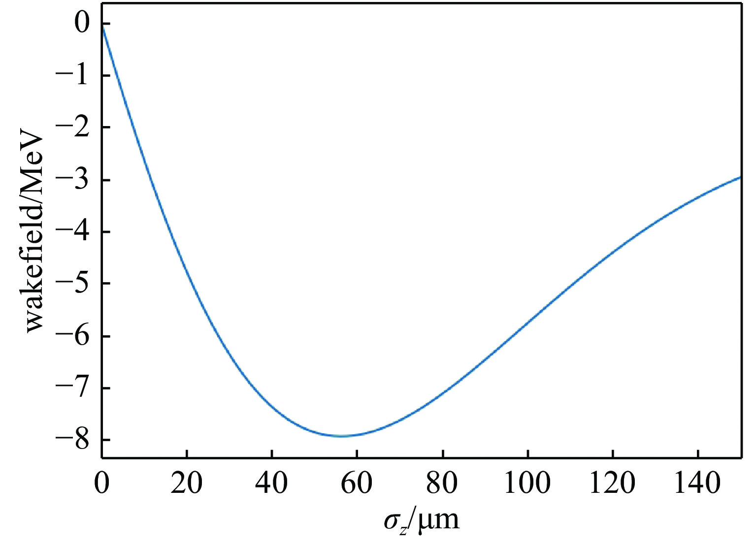
    Fig. 2. Total wakefield in the bypass-line 1 and bypass-line 2. = 0 represents the head of the bunch, and the y-axis represents wakefield in MeV unit
    Wakefield in the copper flat-plate pipe. The = 0 represents the head of the bunch, and the y-axis represents wakefield in MeV unit
    Fig. 3. Wakefield in the copper flat-plate pipe. The = 0 represents the head of the bunch, and the y-axis represents wakefield in MeV unit
    Total wakefield for bypass-line 1, bypass-line 2 and the copper flat-plate pipe. = 0 represents the head of the bunch, and y-axis represents wakefield in MeV unit
    Fig. 4. Total wakefield for bypass-line 1, bypass-line 2 and the copper flat-plate pipe. = 0 represents the head of the bunch, and y-axis represents wakefield in MeV unit
    Experimental layout of SXFEL
    Fig. 5. Experimental layout of SXFEL
    (a) Distribution for bunch A, and (b) measured and calculated wakefields in bypass-line 1
    Fig. 6. (a) Distribution for bunch A, and (b) measured and calculated wakefields in bypass-line 1
    Measured longitudinal phase space in position 1 and position 2. The figure is separated in 500×500 pixels, and x axis stands for bunch length (left is beam head),y stands for the energy (top is higher energy)
    Fig. 7. Measured longitudinal phase space in position 1 and position 2. The figure is separated in 500×500 pixels, and x axis stands for bunch length (left is beam head),y stands for the energy (top is higher energy)
    The energy distribution in position 1 and position 3
    Fig. 8. The energy distribution in position 1 and position 3
    (a) Distribution for bunch B and (b) measured and calculated wakefields for all the pipes
    Fig. 9. (a) Distribution for bunch B and (b) measured and calculated wakefields for all the pipes
    materialtypelength/mradius/mm
    bypass-line 1stainless-steelround12517.50
    bypass-line 2stainless-steelround1208.00
    undulatorcopperflat plate402.15
    Table 1. Parameters of three different types of pipes
    length/µmenergy /GeVcharge/pC
    bunch A2501.35500
    bunch B1201.35500
    Table 2. Initial bunch parameters in SXFEL
    Youwei Gong, Wencai Cheng, Minghua Zhao, Xuan Li, Duan Gu, Meng Zhang. Influence of SXFEL resistive wall wakefield on beam phase space distortion[J]. High Power Laser and Particle Beams, 2022, 34(6): 064007
    Download Citation