• Opto-Electronic Engineering
  • Vol. 49, Issue 4, 210318 (2022)
Jianxin Wang1、2、*, Shuang Chen3, Li Chen3、*, Wenbin Yang3, Rong Qiu1、2, Fuzhong Bai4、*, and Tonghong Li5
Author Affiliations
  • 1Joint Laboratory for Extreme Conditions Matter Properties, Southwest University of Science and Technology, Mianyang, Sichuan 621010, China
  • 2Sichuan Civil-military Integration Institute, Mianyang, Sichuan 621010, China
  • 3Facility Design and Instrumentation Institute, China Aerodynamic Research and Development Center, Mianyang, Sichuan 621000, China
  • 4School of Mechanical Engineering, Inner Mongolia University of Technology, Huhhot, Inner Mongolia 010051, China
  • 5National Center of Quality Inspection and Testing on Diamond Tools, Ezhou, Hubei 436000, China
  • show less
    DOI: 10.12086/oee.2022.210318 Cite this Article
    Jianxin Wang, Shuang Chen, Li Chen, Wenbin Yang, Rong Qiu, Fuzhong Bai, Tonghong Li. Parameters optimization of FLEET optical system[J]. Opto-Electronic Engineering, 2022, 49(4): 210318 Copy Citation Text show less
    FLEET experiment schematic diagram
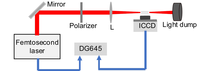
    Fig. 1. FLEET experiment schematic diagram
    Scaling calibration. (a) Original scale; (b) After threshold segmentation; (c) After tilt correction
    Fig. 2. Scaling calibration. (a) Original scale; (b) After threshold segmentation; (c) After tilt correction
    Air fluorescent filament images excited by femtosecond laser with different focal length and laser energy. (a)~(c) With 300 mm focus length and 1 mJ, 2 mJ and 3 mJ laser energy respectively; (d)~(f) With 1000 mm focus length and 1 mJ, 2 mJ and 3 mJ laser energy respectively
    Fig. 3. Air fluorescent filament images excited by femtosecond laser with different focal length and laser energy. (a)~(c) With 300 mm focus length and 1 mJ, 2 mJ and 3 mJ laser energy respectively; (d)~(f) With 1000 mm focus length and 1 mJ, 2 mJ and 3 mJ laser energy respectively
    Process for definition of effective area of fluorescent filament. (a) Projection directions; (b) One dimension curve of projection along x direction, Iy; (c) Projections of signal and background along y direction, Is and In ; (d) Isx curve before and after filtering in space frequency domain; (e) After space frequency filtering of Isx and Inx; (f) Effective area of fluorescent filament
    Fig. 4. Process for definition of effective area of fluorescent filament. (a) Projection directions; (b) One dimension curve of projection along x direction, Iy; (c) Projections of signal and background along y direction, Is and In ; (d) Isx curve before and after filtering in space frequency domain; (e) After space frequency filtering of Isx and Inx; (f) Effective area of fluorescent filament
    Geometric feature extraction of fluorescent filament. (a) Result of binarization; (b) Center line extraction
    Fig. 5. Geometric feature extraction of fluorescent filament. (a) Result of binarization; (b) Center line extraction
    Fluorescent filament SNR and length vs laser power and focal length. (a) SNR curve; (b) Filament length curve
    Fig. 6. Fluorescent filament SNR and length vs laser power and focal length. (a) SNR curve; (b) Filament length curve
    The normalized peak density of air fluorescent filament for different time delay under different pressures
    Fig. 7. The normalized peak density of air fluorescent filament for different time delay under different pressures
    Laser energy /mJ Focal length of focus lens/mm
    17530050010001500
    0.5237591216764750无信号
    1.0205599384023751950无信号
    1.53456415377361428821071
    2.05412989239650437111265
    2.557588913876784445081497
    3.0610190178811090051181795
    Table 1. The maximum gray affected by laser power and focal length
    Laser energy /mJ Focal length of focus lens/mm
    17530050010001500
    0.57.22×10142.46×10148.84×10142.21×10139.82×1012
    1.01.44×10154.91×10141.77×10144.42×10131.96×1013
    1.52.17×10157.37×10142.65×10146.63×10132.95×1013
    2.02.89×10159.82×10143.54×10148.84×10133.93×1013
    2.53.61×10151.23×10154.42×10141.11×10144.91×1013
    3.04.33×10151.47×10155.30×10141.33×10145.89×1013
    Table 2. The laser power density at back focal plane with different laser power and focal length/(W/cm2)
    Jianxin Wang, Shuang Chen, Li Chen, Wenbin Yang, Rong Qiu, Fuzhong Bai, Tonghong Li. Parameters optimization of FLEET optical system[J]. Opto-Electronic Engineering, 2022, 49(4): 210318
    Download Citation