• Photonics Research
  • Vol. 9, Issue 6, 1124 (2021)
Xianglei Yan1、2, Xihua Zou1、2、*, Peixuan Li1、2, Wei Pan1、2, and Lianshan Yan1、2
Author Affiliations
  • 1Center for Information Photonics and Communications, School of Information Science and Technology, Southwest Jiaotong University, Chengdu 611756, China
  • 2International Cooperation Research Center of China: Communications & Sensor Networks for Modern Transportation, Chengdu 611756, China
  • show less
    DOI: 10.1364/PRJ.419605 Cite this Article Set citation alerts
    Xianglei Yan, Xihua Zou, Peixuan Li, Wei Pan, Lianshan Yan. Covert wireless communication using massive optical comb channels for deep denoising[J]. Photonics Research, 2021, 9(6): 1124 Copy Citation Text show less
    Schematic diagram of the covert wireless communication system using massive comb channels. In the transmitting unit the microwave signal is designed to have a flat and large bandwidth and is deeply hidden by strong in-band noises in both the frequency and time domains. In the receiving unit, the transmitting microwave signal is received to modulate an optical carrier, forming an incident microwave photonic signal. A flat OFC is generated with massive and ultradense comb lines for implementing analog spectrum convolution between the OFC and the incident microwave photonic signal, leading to massive spectral replication of the transmitting signal and then a coherent in-phase stacking of massive spectral replicas at the IF point. Extracting the IF signal through a bandpass filter enables the deep denoising for signal recovery, showing a huge SNR improvement. (EOM, electro-optic modulator; IF, inter-frequency; LD, laser diode; OFC, optical frequency comb; PD, photodetector.)
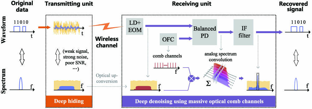
    Fig. 1. Schematic diagram of the covert wireless communication system using massive comb channels. In the transmitting unit the microwave signal is designed to have a flat and large bandwidth and is deeply hidden by strong in-band noises in both the frequency and time domains. In the receiving unit, the transmitting microwave signal is received to modulate an optical carrier, forming an incident microwave photonic signal. A flat OFC is generated with massive and ultradense comb lines for implementing analog spectrum convolution between the OFC and the incident microwave photonic signal, leading to massive spectral replication of the transmitting signal and then a coherent in-phase stacking of massive spectral replicas at the IF point. Extracting the IF signal through a bandpass filter enables the deep denoising for signal recovery, showing a huge SNR improvement. (EOM, electro-optic modulator; IF, inter-frequency; LD, laser diode; OFC, optical frequency comb; PD, photodetector.)
    (a) Analog spectrum convolution in BPD. (b) Recovered signal at the IF point. (c) Comparison between in-phase coherent stacking and random-phase incoherent stacking.
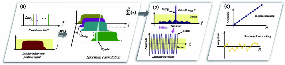
    Fig. 2. (a) Analog spectrum convolution in BPD. (b) Recovered signal at the IF point. (c) Comparison between in-phase coherent stacking and random-phase incoherent stacking.
    Experimental setup for covert wireless communication with deep denoising method. Here the OFCG consists of a PC, an MZM, an EDFA, and an OBPF. (AWG, arbitrary waveform generator; BPD, balanced photodetector; BPF, bandpass filter at the IF point; EDFA, erbium-doped fiber amplifier; HC, host computer; Hybrid, 90° optical hybrid; LD, laser diode; MZM, Mach–Zehnder modulator; OFCG, optical frequency comb generation module; OSC; real-time oscilloscope; PC, polarization controller; OBPF, optical bandpass filter.)
    Fig. 3. Experimental setup for covert wireless communication with deep denoising method. Here the OFCG consists of a PC, an MZM, an EDFA, and an OBPF. (AWG, arbitrary waveform generator; BPD, balanced photodetector; BPF, bandpass filter at the IF point; EDFA, erbium-doped fiber amplifier; HC, host computer; Hybrid, 90° optical hybrid; LD, laser diode; MZM, Mach–Zehnder modulator; OFCG, optical frequency comb generation module; OSC; real-time oscilloscope; PC, polarization controller; OBPF, optical bandpass filter.)
    Designed transmitting microwave signal and strong in-band noises during the deep hiding procedure. (a) Normalized temporal waveform (blue) and normalized spectra (amplitude spectrum, green; phase spectrum, orange) of the transmitting microwave signal. It is designed to have flat spectral and temporal envelopes, a 10.24 GHz bandwidth, and a 1.8 GHz starting frequency. (b) Illustration of the temporal waveforms and the spectra of the transmitting signals and the strong white noises, under in-band SNR of −9 or −18 dB. It is obvious that the microwave signal is deeply buried by the strong noises in both the frequency and time domains.
    Fig. 4. Designed transmitting microwave signal and strong in-band noises during the deep hiding procedure. (a) Normalized temporal waveform (blue) and normalized spectra (amplitude spectrum, green; phase spectrum, orange) of the transmitting microwave signal. It is designed to have flat spectral and temporal envelopes, a 10.24 GHz bandwidth, and a 1.8 GHz starting frequency. (b) Illustration of the temporal waveforms and the spectra of the transmitting signals and the strong white noises, under in-band SNR of 9 or 18  dB. It is obvious that the microwave signal is deeply buried by the strong noises in both the frequency and time domains.
    Recovered signals from the experiment for covert wireless communication demonstration. (a) Optical spectra of the OFC, the incident microwave photonic signal, and the hybrid signal measured at the input of the BPD. (b) Microwave spectrum of the recovered signal observed at the output of the BPD, showing a high peak power or SNR at the 5.2 GHz IF point. (c) Eye diagrams of the recovered PRBS data from the transmitting microwave photonic signal with an SNR of −9 or −18 dB. (MWP, incident microwave photonic signal; OFC, optical frequency comb.)
    Fig. 5. Recovered signals from the experiment for covert wireless communication demonstration. (a) Optical spectra of the OFC, the incident microwave photonic signal, and the hybrid signal measured at the input of the BPD. (b) Microwave spectrum of the recovered signal observed at the output of the BPD, showing a high peak power or SNR at the 5.2 GHz IF point. (c) Eye diagrams of the recovered PRBS data from the transmitting microwave photonic signal with an SNR of 9 or 18  dB. (MWP, incident microwave photonic signal; OFC, optical frequency comb.)
    BER curves measured from experiments and simulations. (a) Experimental results (red spots) and simulation results (blue solid lines) measured through the covert communication experiment (left) and the reference experiment (right). Here a single OFC with 1024 comb lines is employed, indicating a 29 dB SNR improvement at BER of 10−4. (b) Simulation results measured under different comb lines ranging from 1 to 2048, indicating an SNR improvement close to the theoretical prediction of Eq. (11), being compared with one comb channel case. (BER, bit error rate; N, number of comb lines or channels.)
    Fig. 6. BER curves measured from experiments and simulations. (a) Experimental results (red spots) and simulation results (blue solid lines) measured through the covert communication experiment (left) and the reference experiment (right). Here a single OFC with 1024 comb lines is employed, indicating a 29 dB SNR improvement at BER of 104. (b) Simulation results measured under different comb lines ranging from 1 to 2048, indicating an SNR improvement close to the theoretical prediction of Eq. (11), being compared with one comb channel case. (BER, bit error rate; N, number of comb lines or channels.)
    Illustration of three typical situations suffering with beat noises and the optimization analysis for the starting frequencies of the OFC and the incident microwave photonic signal. The left column shows the relative positions in the frequency domain between the OFC and the incident microwave photonic signal before injecting into the BPD; the right one illustrates the corresponding spectrum positions of the recovered signal in the microwave domain. (a) No spectrum overlapping between the optical spectra of the OFC (orange block) and the incident microwave photonic signal (green block). No overlapped beat interference will happen. (b) Slight spectrum overlapping. The overlapped beat interference will happen but will not affect the IF band. (c) Heavy spectrum overlapping. The resultant interference will seriously affect the IF band and thus contaminate the deep denoising. (d1, the difference between the microwave photonic signal’s ending frequency and the OFC’s starting frequency, indicating the degree of spectrum overlapping; d2, the difference between the microwave photonic signal’s starting frequency and the OFC’s ending frequency, indicating the largest beat frequency; ΔB, the bandwidth difference between the microwave photonic signal and the OFC.)
    Fig. 7. Illustration of three typical situations suffering with beat noises and the optimization analysis for the starting frequencies of the OFC and the incident microwave photonic signal. The left column shows the relative positions in the frequency domain between the OFC and the incident microwave photonic signal before injecting into the BPD; the right one illustrates the corresponding spectrum positions of the recovered signal in the microwave domain. (a) No spectrum overlapping between the optical spectra of the OFC (orange block) and the incident microwave photonic signal (green block). No overlapped beat interference will happen. (b) Slight spectrum overlapping. The overlapped beat interference will happen but will not affect the IF band. (c) Heavy spectrum overlapping. The resultant interference will seriously affect the IF band and thus contaminate the deep denoising. (d1, the difference between the microwave photonic signal’s ending frequency and the OFC’s starting frequency, indicating the degree of spectrum overlapping; d2, the difference between the microwave photonic signal’s starting frequency and the OFC’s ending frequency, indicating the largest beat frequency; ΔB, the bandwidth difference between the microwave photonic signal and the OFC.)
    Xianglei Yan, Xihua Zou, Peixuan Li, Wei Pan, Lianshan Yan. Covert wireless communication using massive optical comb channels for deep denoising[J]. Photonics Research, 2021, 9(6): 1124
    Download Citation