
Xianglei Yan, Xihua Zou, Peixuan Li, Wei Pan, Lianshan Yan, "Covert wireless communication using massive optical comb channels for deep denoising," Photonics Res. 9, 1124 (2021)
- Photonics Research
- Vol. 9, Issue 6, 1124 (2021)
Abstract
1. INTRODUCTION
Wireless communications have already penetrated into all corners of our society, with the increasing tides of 5G/B5G, internet of things, ubiquitous access, and cloud computing [1]. Accordingly, the covertness of today’s wireless communications attracts unprecedented interest, when facing great risks to individual privacy and government and military security. As such, the covert wireless communication to achieve a reliable information transmission from transmitter to receiver with low probability of interception has been the focus of academic, industrial, and military communities. Traditionally, besides the encryption methods for content protection, the communication covertness can be enhanced through the electromagnetic signal protection in the physical layer [2–4]. Hiding the transmitting signal deeply under the noise or interference background is one of the prevailing methods to reinforce the physical layer security [5–7]. Furthermore, if the interceptor cannot detect the underlying signal transmission between the transmitter and the receiver, there is no opportunity to launch an “eavesdropping and decoding” attack, even with unlimited computing resource or decryption codes [7]. In general, the deeper the transmitting signal is hid under the noise background with a worse signal-to-noise ratio (SNR), the lower the interception probability for the adversary is [5]. This ensures a higher transmission covertness between transmitter and receiver. However, there is usually a trade-off between the covertness and the fidelity of signal recovery, since a deeper hiding would result in a higher bit error rate (BER) at receiver. To ensure both high covertness and high-fidelity signal recovery, deep hiding and deep denoising should be synchronously satisfied.
Fortunately, the optical frequency comb (OFC), empowering intrinsic coherent exploitation of the overall electromagnetic spectrum [8–10], is generated to have a series of discrete correlated optical comb lines (or teeth) with equal spectral spacing in microwave size [11–20]. In theory, the OFCs are capable of providing enormous comb channels for high-sensitivity spectroscopy and high-capacity microwave/optical signal processing [21–26], as well as for deep denoising in subnoise signal recovery when facing a weak signal or a poor SNR [27–30]. For instance, dual OFCs help to multicast the signal spectrum into multiple replicas through multiple comb lines and then slice the spectrum into a series of subbands (or channels). The coherent stacking of each subband in phase leads to an SNR increase or a net gain linearly proportional to the available subband or channel number. In Ref. [28] the detection of a fast subnoise signal with a big bandwidth and a low power level was implemented with an SNR improvement of 14.1 dB by using dual OFCs, wherein 36 comb lines were generated for signal spectrum replication and coherent stacking. In a follow-up experiment using more than 300 comb lines [29], the SNR was improved by 23.8 dB in contrast to the ideal value of 24.7 dB.
However, the comb channel scalability and the resultant superior limit of SNR increase are unsustainable because of physical bottlenecks on complicated opto-electronic hardware and immense spectrum resources to support massive optical comb channels. In the reports [28,29], dual coherent OFCs with slightly different large free spectral ranges were generated to form a few comb-line pairs, and each pair corresponds to a coherent comb channel. All comb channels are wavelength demultiplexed, and then an inter-frequency (IF) filter and an individual coherent detection are needed for each channel to implement mutual beating between two paired comb lines, requiring dramatically complicated opto-electronic hardware whose size is proportional to the channel number. In this way, it is costly and bulky to support over 100 parallel comb channels, and it is extremely challenging and even impossible with thousands of comb channels. Moreover, the available comb channel number is also constrained by the available wavelength range (i.e., limited spectrum resource). Large comb spacings or coarse comb lines are inevitable for avoiding the beat noises or interference among comb lines and signals, making massive coherent combs nearly impossible. For a large comb spacing (e.g., 0.4 nm [28]) or coarsely distributed comb lines, less than 90 channels are implemented within a given wavelength range such as the C band (e.g., 1530–1565 nm), such that the deep denoising for covert wireless communication is critically degraded.
Sign up for Photonics Research TOC. Get the latest issue of Photonics Research delivered right to you!Sign up now
Here an efficient covert wireless communication system is proposed and demonstrated using deep signal hiding with a very poor incident SNR and deep denoising with a striking SNR rise, wherein massive optical comb channels are enabled by breaking the physical bottlenecks on immense opto-electronic hardware and wavelength resource requirements. In the communication setup, a designed transmitting signal is deeply hidden or heavily contaminated in both the frequency and time domains, for the purpose of high covertness or low interception probability. Massive spectral slices are replicated and then coherently stacked in phase through the analog spectrum convolution. This unique convolution outperforms the digital spectrum convolution or waveform cross-correlation operation in spread spectrum communication in terms of being ultrafast, having nearly zero latency, and having memoryless analog operation. As such, the signal’s power level is greatly proliferated in a coherent mode, but the noise level retains nearly unchanged in an incoherent mode. Thus, the deep denoising is achieved for subnoise signal recovery with a striking SNR improvement. As a demonstration, an OFC with 1024 comb lines and a 10 MHz comb spacing is generated for detecting and recovering an incident microwave signal with a 10.24 GHz bandwidth, a 10 Mbit/s data rate, and a poor SNR ranging from
2. COVERT WIRELESS COMMUNICATION SYSTEM USING MASSIVE COMB CHANNELS
The covert communication system using massive comb channels is depicted in Fig. 1, consisting of a transmitting unit for deep hiding and a receiving unit for deep denoising. The original data is processed to have weak, flat spectral and temporal envelopes in the microwave domain, which is deeply hidden below noise in both the frequency and time domains. Such a noisy microwave signal with a weak power level and a poor SNR is radiated toward the receiving unit through the wireless channel. In the receiving unit, the acquired microwave signal is modulated on an optical carrier through electro-optic modulation, generating the incident microwave photonic signal. Actually, the incident microwave photonic signal is identical or equivalent to the transmitting microwave signal, except for the central frequency being up-converted from the microwave to the optical domain in single sideband modulation mode. Next, a flat ultradense OFC with
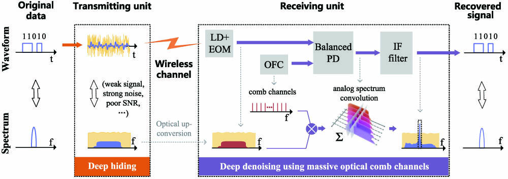
Figure 1.Schematic diagram of the covert wireless communication system using massive comb channels. In the transmitting unit the microwave signal is designed to have a flat and large bandwidth and is deeply hidden by strong in-band noises in both the frequency and time domains. In the receiving unit, the transmitting microwave signal is received to modulate an optical carrier, forming an incident microwave photonic signal. A flat OFC is generated with massive and ultradense comb lines for implementing analog spectrum convolution between the OFC and the incident microwave photonic signal, leading to massive spectral replication of the transmitting signal and then a coherent in-phase stacking of massive spectral replicas at the IF point. Extracting the IF signal through a bandpass filter enables the deep denoising for signal recovery, showing a huge SNR improvement. (EOM, electro-optic modulator; IF, inter-frequency; LD, laser diode; OFC, optical frequency comb; PD, photodetector.)
Therefore, a huge SNR improvement proportional to the comb channel number can be achieved at the IF point. The received transmitting microwave signal or the incident microwave photonic signal can be deeply denoised, and the original data can be correctly recovered through the IF signal. In this way, both high covertness and high-fidelity signal recovery are ensured in this OFC-enabled wireless communication system.
A. Deep Hiding with Poor SNR in Both the Frequency and Time Domains
For high covertness, deep signal hiding is implemented in the transmitting unit. White Gaussian noises or other artificial noises and interferences [6] with a relatively higher power level are generated to deeply bury the microwave signal before radiation out. Along the flat and broadband weak power distribution of the microwave signal, the in-band SNR in the frequency domain should be as low as
B. Photonic Assisted Analog Spectrum Convolution
The key to the success of the covert communication lies in the deep denoising at the receiving unit, which is implemented by using analog spectrum convolution and massive coherent stacking. Mathematically, we start from a flat and ultradense OFC with
The incident microwave photonic signal covers a frequency range from
When the OFC and the incident microwave photonic signal are coupled into the BPD, an output signal is derived as
Here
Equation (5) shows the analog spectrum convolution of the OFC and the photonic signal, which is equivalently described in the electrical domain through opto-electrical conversion using the BPD. The analog spectrum convolution, showing ultrafast and memoryless advantages over digital convolution or correlation operations in, for example, traditional spread spectrum communications, can be regarded as the sum of multiple weighted (both amplitude and phase) replicas of inversed and frequency-shifted spectrum of the photonic signal.
For a vivid demonstration of analog spectrum convolution, Fig. 2 shows the detailed process happening in the BPD. As depicted in Fig. 2(a), the spectrum of the incident microwave photonic signal is massively replicated, and the IF point locates in the overlapping range of all replicated spectra. Through the in-phase coherent stacking, the recovered signal at the IF point has a high amplitude gain as illustrated in Fig. 2(b). Meanwhile, as a comparison, the in-phase coherent stacking for the incident microwave photonic signal and random-phase incoherent stacking for the white Gaussian noise are shown Fig. 2(c). Obviously, the incident microwave photonic signal will get an amplitude (or power) gain from the in-phase stacking, while no amplitude (or power) gain for the noise. Such a principle is just behind the SNR improvement of our covert communication system, which will be explained with more detail in the following.
![]()
Figure 2.(a) Analog spectrum convolution in BPD. (b) Recovered signal at the IF point. (c) Comparison between in-phase coherent stacking and random-phase incoherent stacking.
C. SNR Improvement for Deep Denoising
To quantitatively analyze the SNR improvement from the deep denoising, both the OFC and the incident microwave photonic signal (equivalently the transmitting microwave signal) are designed to have relative flat spectral envelopes. Furthermore,
For SNR analysis, we have to first extract the IF signal at the IF point defined as
It is clear that a huge gain linearly proportional to the number of comb lines (i.e., comb channel number N) provided by the OFC can be achieved at the IF point, and the output average power can be derived as
For the noise (e.g., white Gaussian noise), an in-phase stacking will not occur since its phase is randomly distributed. Let us define the original average spectral power of the white Gaussian noise along with the incident microwave photonic signal is
D. Random Phases for Transmitting Microwave Signal and Massive Optical Comb Lines
To reinforce the low interception probability, either the transmitting microwave signal or the OFC should not be specified to have constant phase distribution within the effective bandwidth, to avoid a high peak in the time domain.
Besides a wide bandwidth and a low, flat spectral envelope, which enable the coherent in-phase stacking of massive spectral slices, the incident microwave signal is also required to have random phase distribution. Given a constant phase distribution, a high peak will appear and make the transmitting microwave signal easily detected in the time domain, which disables the low-interception feature regardless of a poor SNR or a weak average power level. Therefore, a random (actually pseudorandom) phase distribution is designed to provide a relatively uniform, weak power distribution in the time domain for high covertness. The peak to average power ratio (PAPR) of a 10.24 GHz wideband signal can be reduced by more than 200 times when using a randomly distributed phase instead of a constant one in our experiment. Besides, the random phase distribution can be reused for a long time, with very low risk on communication vulnerability, due to the deep hiding in the physical layer and extreme complexity for brute force attacks. Moreover, for a dynamically changed random phase distribution to improve the covertness further, the overhead for transmitting of the random phase key is still very small.
The same situation applies for the phase distribution of the OFC used. An OFC is usually with constant or weak-perturbation phase distribution among comb lines, which dominantly determines its temporal waveform such as soliton pulses or other pulses [11–16,18,19]. If such a constant or weak-perturbation phase distribution is implemented, several negative problems obviously occur by considering the extremely nonuniform temporal power distribution and the high peak power. First, the high peak impedes their subsequent amplification in the fiber link. Second, the high peak will bring nonlinear distortions [31] and even equipment damage [32,33]. Therefore, a random or pseudorandom phase is optimized and applied to make a relative uniform power distribution in the time domain for the OFC. More importantly, the random phase distribution of the transmitting microwave signal should synchronously match the OFC’s random phase distribution to achieve massive in-phase spectrum stacking for deep denoising.
In addition, the unbalance of the BPD will introduce some signal-to-signal beating notes or noises in the low frequency range, arising from the self-beating of the incident microwave photonic signal and the OFC. Fortunately, by using a random phase distribution, different beat notes at the same frequency are generated with random phases, and then the coherent stackings among them will randomly cancel each other. This phenomenon has twofold benefits: avoiding the signal-to-signal beat noises to signal recovery and relaxing the saturated output power of the BPD.
E. Breaking Physical Bottlenecks on Immense Hardware and Spectrum Resource Requirements
Traditional coherent denoising methods replicate the target microwave signal in parallel paths and then coherently stack them to improve the SNR [27]. However, immense requirements on hardware and spectrum resources set critical physical bottlenecks for massive comb channels, when facing a huge SNR improvement requirement from deep denoising after deep hiding. The physical bottlenecks are understood in two aspects. First, each comb-line pair with two comb lines from dual combs should be wavelength demultiplexed and then detected parallelly and separately in individual mode [28,29] to form one comb channel. Massive comb channels will require a dramatically complicated opto-electronic hardware consisting of parallel demultiplexing and detection branches proportional to the comb channel number. Such a hardware complexity is unsustainable, costly, and bulky for supporting thousands of channels and more. Second, when all comb-line pairs (comb channels) are detected in one joint branch without wavelength demultiplexing and individual detection, large comb spacings or sparse comb lines should be specified to avoid the harmful self-beating noises among different comb lines and the incident microwave photonic signal. Massive comb channels will request a dramatically wide optical spectrum proportional to the comb channel number, due to the low spectral efficiency. Such a wide spectrum is also extremely challenging and even impossible for accommodating thousands of channels and more. As an example, 1000 channels with a comb spacing of 0.4 nm will occupy a 400 nm spectrum resource, which is far beyond the total bandwidth of low-loss windows (C band, L band, and U band) of optical fiber.
Fortunately, the physical bottlenecks on hardware and spectrum resources have been broken or greatly mitigated in this proposed deep denoising method, because massive comb channels are implemented using a single detection branch and a narrow wavelength bandwidth of several nanometers, while removing the linear increase on hardware complexity and the self-beat interferences. Since only one detection branch is used, the detected signal should be shifted to an IF band to eliminate the overlapped beat interference (see Section 4 for more details), requiring a higher frequency for the narrow-bandwidth IF processing in contrast to Refs. [28,29].
3. EXPERIMENTS AND DEMONSTRATIONS
A. Deep Denoising for Covert Wireless Communication
An experimental setup to implement covert wireless communication is established, using massive comb channels for deep coherent denoising through a single detection branch. As shown in Fig. 3, the original data (e.g., 11010) from a host computer is up-converted to generate a microwave signal in differential binary phase-shift keying (DBPSK) format. In the transmitting unit, the original data [i.e., a pseudorandom binary sequence (PRBS) with a 320 bit length and a 10 Mbit/s rate] is first encoded to obtain differential code which is then applied to phase modulate a microwave carrier, generating the transmitting microwave signal spanning from 1.8 to 12.04 GHz. The microwave carrier, which has a flat spectrum envelope and a random phase distribution, is designed through inverse fast Fourier transform (IFFT). Since a random phase distribution is applied, this generated transmitting microwave signal is deeply hidden below strong noise background and then radiated out.
![]()
Figure 3.Experimental setup for covert wireless communication with deep denoising method. Here the OFCG consists of a PC, an MZM, an EDFA, and an OBPF. (AWG, arbitrary waveform generator; BPD, balanced photodetector; BPF, bandpass filter at the IF point; EDFA, erbium-doped fiber amplifier; HC, host computer; Hybrid, 90° optical hybrid; LD, laser diode; MZM, Mach–Zehnder modulator; OFCG, optical frequency comb generation module; OSC; real-time oscilloscope; PC, polarization controller; OBPF, optical bandpass filter.)
Inside the receiving unit, the subnoise microwave signal is captured. An optical carrier from a continuous-wave and narrow-linewidth laser is split into two parts. One part is modulated by the acquired noisy microwave signal inside a Mach–Zehnder modulator (MZM) to form the incident microwave photonic signal, while the other being processed to generate a customized OFC with massive and ultradense comb lines. Next, both the incident microwave photonic signal and the OFC are converged by a 90° optical hybrid and fed into a BPD simultaneously, wherein massive spectral replication and in-phase coherent stacking of massive spectral slices at the IF point are implemented. Following the BPD, an electrical bandpass filter with twice the bandwidth of the original data is employed to extract the spectral components falling inside the IF band. Then the differential coherent demodulation is implemented to recover the original data carried by the transmitting microwave signal with a much higher SNR. Consequently, the original data is recovered from strong noise background and then recorded by using a real-time oscilloscope.
As aforementioned, a random phase distribution is designed for the transmitting microwave signal to keep a low, uniform power distribution in both the frequency and time domains. Figure 4(a) shows the normalized temporal waveform and the amplitude/phase spectra of the designed transmitting microwave signal having a 10.24 GHz bandwidth and a 1.8 GHz starting frequency. To quantitatively evaluate the performance of the deep denoising, PRBS data are curved on the transmitting microwave signal in DBPSK format, while white noise is added to emulate different SNRs during the deep hiding in tests. It is highlighted that here the in-band noise or SNR is considered, rather global all-band ones, since most out-band noises can be reasonably eliminated by using a matching filter. In details, Fig. 4(b) shows the temporal waveforms and spectra of the normalized transmitting microwave signal, together with white noises. Regarding an in-band SNR of
![]()
Figure 4.Designed transmitting microwave signal and strong in-band noises during the deep hiding procedure. (a) Normalized temporal waveform (blue) and normalized spectra (amplitude spectrum, green; phase spectrum, orange) of the transmitting microwave signal. It is designed to have flat spectral and temporal envelopes, a 10.24 GHz bandwidth, and a 1.8 GHz starting frequency. (b) Illustration of the temporal waveforms and the spectra of the transmitting signals and the strong white noises, under in-band SNR of
Here the OFC is generated through the module depicted in Fig. 3, using a carrier-suppressed and single-sideband (CS-SSB) modulation architecture. During the OFC generation, both electrical and optical procedures are implemented. A user-defined electrical signal with a flat spectral envelope starting from 7 GHz and a random phase (corresponding to the random phase of the microwave carrier used to generate the incident microwave signal as depicted in Section 2.C) is generated from an arbitrary waveform generator (AWG, Keysight-M8195A). The user-defined electrical signal is then applied to intensity modulate the optical carrier inside an MZM biased at the minimum point of its transfer function for carrier suppression. The generated optical signal has a flat spectral envelope starting from
![]()
Figure 5.Recovered signals from the experiment for covert wireless communication demonstration. (a) Optical spectra of the OFC, the incident microwave photonic signal, and the hybrid signal measured at the input of the BPD. (b) Microwave spectrum of the recovered signal observed at the output of the BPD, showing a high peak power or SNR at the 5.2 GHz IF point. (c) Eye diagrams of the recovered PRBS data from the transmitting microwave photonic signal with an SNR of
This OFC is converged with the microwave photonic signal and the hybrid optical spectrum is also recorded. At the output of the BPD, the recovered signal after analog spectrum convolution and massive in-phase stacking is recorded and shown in Fig. 5(b), indicating a high peak power and a high SNR at the 5.2 GHz IF point (
B. SNR Enhancement and Performance Comparison
To quantitatively analyze the SNR enhancement of the deep denoising in the covert communication system, incident microwave photonic signals (equivalently the noisy transmitting microwave signal) with different in-band SNRs ranging from
![]()
Figure 6.BER curves measured from experiments and simulations. (a) Experimental results (red spots) and simulation results (blue solid lines) measured through the covert communication experiment (left) and the reference experiment (right). Here a single OFC with 1024 comb lines is employed, indicating a 29 dB SNR improvement at BER of
For a given BER at
To reveal the comb channel scalability or the impact of the comb channel number, simulations are carried out by gradually increasing the comb channels from 1 to 2048. The resulted BER curves for the recovered signal from the same transmitting microwave signal having a 10.24 GHz bandwidth and a 10 Mbit/s data rate are analyzed and shown in Fig. 6(b), indicating an SNR improvement well in line with Eq. (11). Consequently, the gain or the SNR rise is sustainable by using simple but elegant opto-electronic hardware.
The starting frequencies of the OFC and the incident microwave photonic signal should be carefully allocated to avoid some serious beat notes or noises, and details can be found in Section 4. In the experiments and simulations above, the OFC is generated to have a starting frequency at
4. DISCUSSION
The starting frequencies of the OFC and the incident microwave photonic signal should be carefully specified to avoid serious signal-to-signal beat notes or noises. Typically, there are three situations suffering from beat noises as shown in Fig. 7.
![]()
Figure 7.Illustration of three typical situations suffering with beat noises and the optimization analysis for the starting frequencies of the OFC and the incident microwave photonic signal. The left column shows the relative positions in the frequency domain between the OFC and the incident microwave photonic signal before injecting into the BPD; the right one illustrates the corresponding spectrum positions of the recovered signal in the microwave domain. (a) No spectrum overlapping between the optical spectra of the OFC (orange block) and the incident microwave photonic signal (green block). No overlapped beat interference will happen. (b) Slight spectrum overlapping. The overlapped beat interference will happen but will not affect the IF band. (c) Heavy spectrum overlapping. The resultant interference will seriously affect the IF band and thus contaminate the deep denoising. (
For simplicity, the starting frequency of the OFC (orange block) is larger than that of the incident microwave photonic signal (green block), and the bandwidth (width of orange block) of the OFC is less than that of the incident microwave photonic signal (width of green block). The subfigures on left column describe the relative position in the frequency domain before injecting into the BPD, and the ones on right column illustrate the spectrum position of the recovered microwave signal. As depicted in Fig. 7(a), when there is no overlapping between the optical spectra of the OFC and the incident microwave photonic signal, the recovered signal has a starting frequency equal to d1 and an ending frequency equal to d2, where d1 and d2 are defined in the caption of Fig. 7. Here
To avoid beat notes arising from the third situation [Fig. 7(c)], a sufficient constraint relationship between the starting frequencies and bandwidths is derived and demonstrated in the following. The difference between their starting frequencies has a minimum value to ensure an effective IF point for beat interference-free measurement, when the bandwidth of the OFC and the incident microwave photonic signal is fixed. That means the maximum of the overlapped microwave frequency range must be smaller than the IF point inside the optional range depicted as the red block in Fig. 7. Mathematically, the constraint relationship is derived as
Meanwhile, substituting
The arrival time of the incident microwave photonic signal plays an important role in the deep denoising. A relative time delay
5. CONCLUSION
A covert wireless communication system using massive comb channels has been proposed and experimentally demonstrated. Through the deep signal hiding below the noise background and the deep signal denoising from poor SNR conditions, both high covertness and high-fidelity signal recovery are realized. This simple and elegant optical system enables an ultrafast and memoryless analog spectrum convolution without complicated digital processing and breaks the physical bottlenecks on the costly and bulk opto-electronic hardware and limited optical wavelength spectrum resource for implementing massive coherent channels. In the demonstrated system, a single OFC is generated through CS-SSB modulation. The generated OFC with 1024 comb lines and an ultradense comb spacing is used for massive spectral replication and coherent in-phase stacking of massive comb channels. After deep hiding with a poor in-band SNR of
References
[1] A. Goldsmith. Wireless Communications(2005).
[2] S. Yan, X. Zhou, J. Hu, S. V. Hanly. Low probability of detection communication: opportunities and challenges. IEEE Wireless Commun., 26, 19-25(2019).
[3] Z. Liu, J. Liu, Y. Zeng, J. Ma. Covert wireless communication in IOT network: from AWGN channel to THz band. IEEE Internet Things, 7, 3378-3388(2020).
[4] M. K. Simon, J. K. Omura, R. A. Scholtz, B. K. Levitt. Spread Spectrum Communications Handbook(1994).
[5] B. A. Bash, D. Goeckel, D. Towsley, S. Guha. Hiding information in noise: fundamental limits of covert wireless communication. IEEE Commun. Mag., 53, 26-31(2015).
[6] R. Soltani, D. Goeckel, D. Towsley, B. A. Bash, S. Guha. Covert wireless communication with artificial noise generation. IEEE Trans. Wireless Commun., 17, 7252-7267(2018).
[7] Z. Liu, J. Liu, Y. Zeng, J. Ma. Covert wireless communications in IOT systems: hiding information in interference. IEEE Wireless Commun., 25, 46-52(2018).
[8] T. Fortier, E. Baumann. 20 years of developments in optical frequency comb technology and applications. Commun. Phys., 2, 153(2019).
[9] S. A. Diddams, K. Vahala, T. Udem. Optical frequency combs: coherently uniting the electromagnetic spectrum. Science, 369, eaay3676(2020).
[10] M. Giunta, M. Fischer, W. Hänsel, T. Steinmetz, M. Lessing, S. Holzberger, C. Cleff, T. W. Hänsch, M. Mei, R. Holzwarth. 20 years and 20 decimal digits: a journey with optical frequency combs. IEEE Photon. Technol. Lett., 31, 1898-1901(2019).
[11] T. Herr, V. Brasch, J. D. Jost, C. Y. Wang, N. M. Kondratiev, M. L. Gorodetsky, T. J. Kippenberg. Temporal solitons in optical microresonators. Nat. Photonics, 8, 145-152(2014).
[12] V. Brasch, M. Geiselmann, T. Herr, G. Lihachev, M. H. Pfeiffer, M. L. Gorodetsky, T. J. Kippenberg. Photonic chip–based optical frequency comb using soliton Cherenkov radiation. Science, 351, 357-360(2016).
[13] A. Parriaux, K. Hammani, G. Millot. Electro-optic frequency combs. Adv. Opt. Photon., 12, 223-287(2020).
[14] M. Zhang, B. Buscaino, C. Wang, A. Shams-Ansari, C. Reimer, R. Zhu, J. M. Kahn, M. Lončar. Broadband electro-optic frequency comb generation in a lithium niobate microring resonator. Nature, 568, 373-377(2019).
[15] A. Rueda, F. Sedlmeir, M. Kumari, G. Leuchs, H. G. Schwefel. Resonant electro-optic frequency comb. Nature, 568, 378-381(2019).
[16] J. Ma, X. Jiang, M. Xiao. Kerr frequency combs in large-size, ultra-high-
[17] X. Yan, X. Zou, W. Pan, L. Yan, J. Azaña. Fully digital programmable optical frequency comb generation and application. Opt. lett., 43, 283-286(2018).
[18] A. L. Gaeta, M. Lipson, T. J. Kippenberg. Photonic-chip-based frequency combs. Nat. Photonics, 13, 158-169(2019).
[19] C. Qin, K. Jia, Q. Li, T. Tan, X. Wang, Y. Guo, S.-W. Huang, Y. Liu, S. Zhu, Z. Xie, Y. Rao, Y. Baicheng. Electrically controllable laser frequency combs in graphene-fibre microresonators. Light Sci. Appl., 9, 185(2020).
[20] J. Pan, B. Zhang, Z. Liu, J. Zhao, Y. Feng, L. Wan, Z. Li. Microbubble resonators combined with a digital optical frequency comb for high-precision air-coupled ultrasound detectors. Photon. Res., 8, 303-310(2020).
[21] X. Wei, Y. Shen, J. C. Jing, A. S. Hemphill, C. Yang, S. Xu, Z. Yang, L. V. Wang. Real-time frequency-encoded spatiotemporal focusing through scattering media using a programmable 2D ultrafine optical frequency comb. Sci. Adv., 6, eaay1192(2020).
[22] N. Picqué, T. W. Hänsch. Frequency comb spectroscopy. Nat. Photonics, 13, 146-157(2019).
[23] Y. Bao, X. Yi, Z. Li, Q. Chen, J. Li, X. Fan, X. Zhang. A digitally generated ultrafine optical frequency comb for spectral measurements with 0.01-pm resolution and 0.7-μs response time. Light Sci. Appl., 4, e300(2015).
[24] V. Torres-Company, A. M. Weiner. Optical frequency comb technology for ultra-broadband radio-frequency photonics. Laser Photon. Rev., 8, 368-393(2014).
[25] P. Marin-Palomo, J. N. Kemal, M. Karpov, A. Kordts, J. Pfeifle, M. H. Pfeiffer, P. Trocha, S. Wolf, V. Brasch, M. H. Anderson, R. Rosenberger, K. Vijayan, W. Freude, T. J. Kippenberg, C. Koos. Microresonator-based solitons for massively parallel coherent optical communications. Nature, 546, 274-279(2017).
[26] X. Xu, J. Wu, T. G. Nguyen, M. Shoeiby, S. T. Chu, B. E. Little, R. Morandotti, A. Mitchell, D. J. Moss. Advanced RF and microwave functions based on an integrated optical frequency comb source. Opt. Express, 26, 2569-2583(2018).
[27] R. N. McDonough, A. D. Whalen. Detection of Signals in Noise(1995).
[28] V. Ataie, D. Esman, B. P.-P. Kuo, N. Alic, S. Radic. Subnoise detection of a fast random event. Science, 350, 1343-1346(2015).
[29] D. Esman, V. Ataie, B. P.-P. Kuo, N. Alic, S. Radic. Subnoise signal detection and communication. J. Lightwave Technol., 34, 5214-5219(2016).
[30] B. Crockett, L. R. Cortés, S. R. Konatham, J. Azaña. Single-shot subnoise signal recovery by coherent spectral energy redistribution. CLEO: Applications and Technology, JW2A-71(2019).
[31] G. Agrawal. Nonlinear Fiber Optics(2012).
[32] R. M. Wood. Laser Damage in Optical Materials(1986).
[33] B. C. Stuart, M. D. Feit, S. M. Herman, A. M. Rubenchik, B. W. Shore, M. D. Perry. Ultrashort-pulse optical damage. Proc. SPIE, 2714, 616-629(1996).


Set citation alerts for the article
Please enter your email address

© Copyright 2018-2021 | Chinese Laser Press. All Rights Reserved 沪ICP备15018463号-20