• Chinese Optics Letters
  • Vol. 14, Issue 8, 080501 (2016)
Shiyao Fu1, Tonglu Wang2, Yan Gao1, and Chunqing Gao1、*
Author Affiliations
  • 1School of Opto-Electronics, Beijing Institute of Technology, Beijing 100081, China
  • 2School of Physics, Beijing Institute of Technology, Beijing 100081, China
  • show less
    DOI: 10.3788/COL201614.080501 Cite this Article Set citation alerts
    Shiyao Fu, Tonglu Wang, Yan Gao, Chunqing Gao. Diagnostics of the topological charge of optical vortex by a phase-diffractive element[J]. Chinese Optics Letters, 2016, 14(8): 080501 Copy Citation Text show less
    Phase profile of the diffractive optical element.
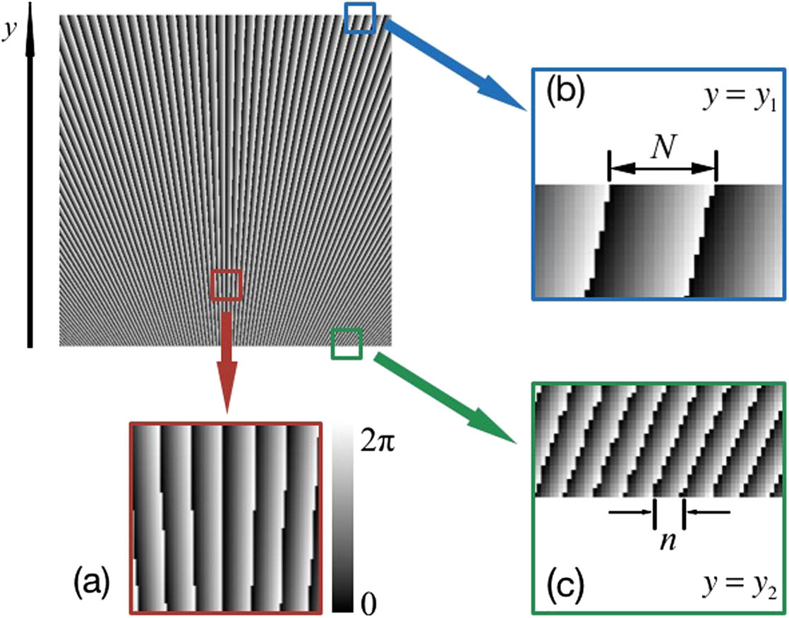
    Fig. 1. Phase profile of the diffractive optical element.
    Normalized intensity distribution of the incident optical vortices and the simulated far-field diffraction patterns. (a), (b), and (c) are the incident single-ring (radial index p=0) optical vortices with topological charge l=1, l=−1, and l=2, respectively. (d) and (e) are the incident multi-ring incident optical vortices with topological charge l=1 and l=−1. (f), (g), (h), (i), and (j) are the simulation results of the normalized intensity distribution of the far-field diffraction when the optical vortices shown in (a), (b), (c), (d), and (e) propagate through the diffractive optical element, respectively. (k) and (l) are the 3D images of the normalized intensity distributions of (c) and (h).
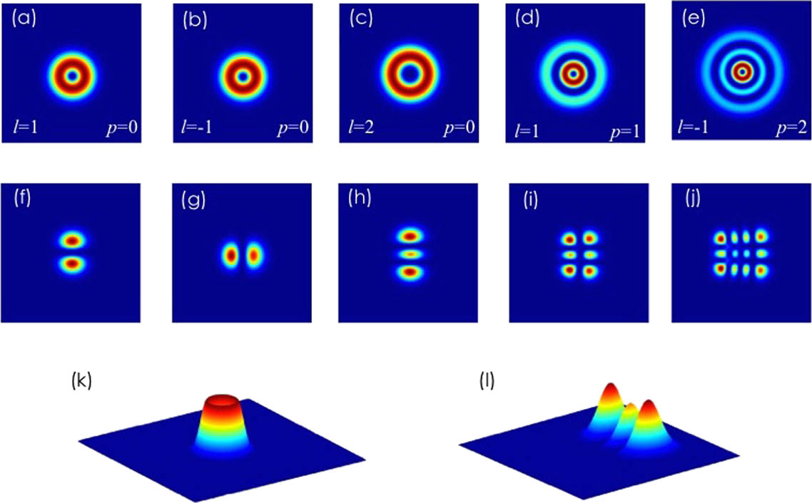
    Fig. 2. Normalized intensity distribution of the incident optical vortices and the simulated far-field diffraction patterns. (a), (b), and (c) are the incident single-ring (radial index p=0) optical vortices with topological charge l=1, l=1, and l=2, respectively. (d) and (e) are the incident multi-ring incident optical vortices with topological charge l=1 and l=1. (f), (g), (h), (i), and (j) are the simulation results of the normalized intensity distribution of the far-field diffraction when the optical vortices shown in (a), (b), (c), (d), and (e) propagate through the diffractive optical element, respectively. (k) and (l) are the 3D images of the normalized intensity distributions of (c) and (h).
    Two examples of the detecting procedure of our method. (a) The case of a single-ring optical vortex with l=+4. (b) The case of a multi-ring optical vortex with l=−2.
    Fig. 3. Two examples of the detecting procedure of our method. (a) The case of a single-ring optical vortex with l=+4. (b) The case of a multi-ring optical vortex with l=2.
    Experimental setup to diagnose the topological charge of the optical vortex. LD, laser diode; SMF, single mode fiber; Col., collimator; L, convex lens.
    Fig. 4. Experimental setup to diagnose the topological charge of the optical vortex. LD, laser diode; SMF, single mode fiber; Col., collimator; L, convex lens.
    Holograms of the spiral phase plate and the simulation results of the generated LG modes. From (a) to (e) are the spiral phase plates to generate the LG0–1 mode, LG05 mode, LG1–1 mode, LG13 mode, and LG21 mode, separately. (f), (g), (h), (i), and (j) are the simulation results of the far-field diffraction patterns when the Gaussian beams propagate through the holograms above.
    Fig. 5. Holograms of the spiral phase plate and the simulation results of the generated LG modes. From (a) to (e) are the spiral phase plates to generate the LG01 mode, LG05 mode, LG11 mode, LG13 mode, and LG21 mode, separately. (f), (g), (h), (i), and (j) are the simulation results of the far-field diffraction patterns when the Gaussian beams propagate through the holograms above.
    Experimental results of the incident single-ring optical vortices. (a) The case of the optical vortices with a positive topological charge. (b) The case of the optical vortices with a negative topological charge. In each submap, from top to bottom are the incident optical vortices, simulation results, and experimental results, respectively.
    Fig. 6. Experimental results of the incident single-ring optical vortices. (a) The case of the optical vortices with a positive topological charge. (b) The case of the optical vortices with a negative topological charge. In each submap, from top to bottom are the incident optical vortices, simulation results, and experimental results, respectively.
    Experimental results of the incident multi-ring optical vortices. From left to right are the LG11 mode, LG1–1 mode, LG13 mode, LG21 mode, and LG2−1 mode, separately. From top to bottom are the incident multi-ring optical vortices, simulation results, and experimental results, respectively.
    Fig. 7. Experimental results of the incident multi-ring optical vortices. From left to right are the LG11 mode, LG11 mode, LG13 mode, LG21 mode, and LG21 mode, separately. From top to bottom are the incident multi-ring optical vortices, simulation results, and experimental results, respectively.
    Shiyao Fu, Tonglu Wang, Yan Gao, Chunqing Gao. Diagnostics of the topological charge of optical vortex by a phase-diffractive element[J]. Chinese Optics Letters, 2016, 14(8): 080501
    Download Citation