
Yanke Li, Yu Zou, Sheng Liu, Peng Li, Bingyan Wei, Jianlin Zhao, "Linear and nonlinear photonic spin Hall effect induced by analog circular birefringence of Bessel-like beams," Photonics Res. 11, 1553 (2023)
- Photonics Research
- Vol. 11, Issue 9, 1553 (2023)
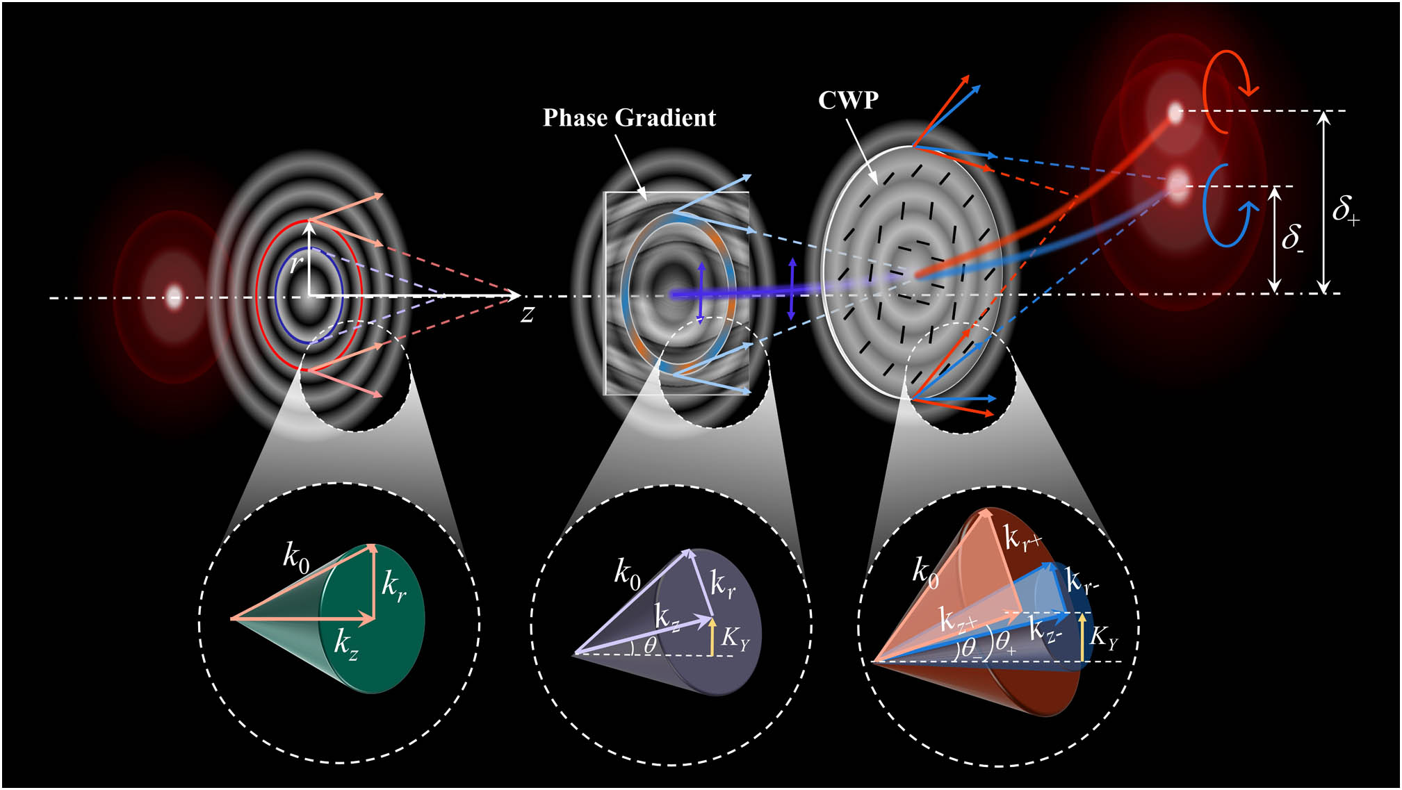
Fig. 1. Schematic of the realization of analog off-axis circular birefringence of the Bessel beam.
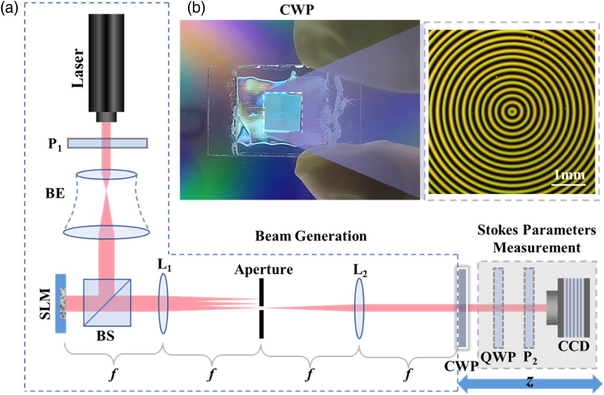
Fig. 2. (a) Experimental setup. Laser, He–Ne laser of wavelength 632.8 nm; P, polarizer; BE, beam expander; SLM, spatial light modulator; BS, beam splitter; L, lens; QWP, quarter-wave plate. (b) Photograph and micrograph of the CWP.
Fig. 3. Photonic spin Hall effect (PSHE) of tilting Bessel beam passing through a CWP. (a) Theoretical result of the spin separation at different oblique angle; (b)–(d) postselection results of weak measurement; (e) comparison of the experimental results along the vertical dot lines in (b)–(d).
Fig. 4. Enhancement of PSHE by introducing a parabolic Bessel-like beam. (a)–(h) Intensity distributions of the light field at different distances, with the normalized Stokes parameter s 3
Fig. 5. Control of PSHE by Bessel-like beam with spliced trajectory. (a)–(h) Intensity distributions with s 3
Fig. 6. Enhanced PSHE induced by different self-accelerating Bessel-like beams. (a) Bessel-like beam along a cosine-like curve in Ref. [42]; (b) spiral Bessel-like beam in Ref. [43].
Fig. 7. Parabolic Bessel-like beam. (a) Amplitude distribution of input Bessel beam; (b) phase gradient attached to the input beam; (c) side view of the simulated propagation process, with the pre-designed trajectory marked by the blue dashed line.
Fig. 8. Bessel-like beam with a spliced trajectory. The input amplitude is the same as Fig. 7 (a). (a) Phase gradient attached to the input beam, where the white dashed line marks the boundary of the two phase gradients, corresponding to the trajectories at different distances, respectively; (b) side view of the simulated propagation process, with the pre-designed trajectory marked by the blue dashed line.
Fig. 9. Simulation results of transforming the PSHE to the axial CB. (a) Side view of the simulated propagation process; (b)–(e) intensities of the beam passing through two orthogonal analyzers during stable axial CB (after 20 cm), where the double-arrows denote the orientations of analyzers.
Fig. 10. Phases for generating (a) the cosine Bessel-like beam in Ref. [42] and (b) the spiral Bessel-like beam in Ref. [43].
Fig. 11. Simulation results of the PSHE of parabolic first-order Bessel-like beam. (a)–(d) Intensity distributions of the beam at different distance; (e) offsets of the different spin states versus propagation distance.


Set citation alerts for the article
Please enter your email address

© Copyright 2018-2021 | Chinese Laser Press. All Rights Reserved 沪ICP备15018463号-20