1Key Laboratory of Light Field Manipulation and Information Acquisition, Ministry of Industry and Information Technology, and Shaanxi Key Laboratory of Optical Information Technology, School of Physical Science and Technology, Northwestern Polytechnical University, Xi’an 710129, China
2Collaborative Innovation Center of Light Manipulation and Applications, Shandong Normal University, Jinan 250358, China
The spin Hall effect of a light beam is essentially a product of circular birefringence but is rarely demonstrated. Here, we provide a scheme for initiating off-axis circular birefringence based on the spin-dependent wave vector bifurcation of Bessel beams via a single liquid crystal Pancharatnam–Berry phase element. The tilted Bessel beam shows a detectable photonic spin Hall effect. By introducing the nonlinear propagation trajectories, the spin Hall effect is greatly enhanced. More surprisingly, the two spin states exactly propagate along the scaled trajectories, enabling flexible control of the spin separation. This phenomenon is also applicable to other Bessel-like beams with nonlinear trajectories, which have been already reported.
1. INTRODUCTION
The photonic spin Hall effect (PSHE), commonly referring to the analogy of the spin Hall effect in electronic systems, is now being extensively studied due to its important applications in nano-optics, singular optics, photonics, and metamaterials [1,2]. It was considered as a manifestation of photonic spin–orbit interaction [3] and was proposed during the beam reflection and refraction at the media interface [4]. After that, several types of setups or artificial structures have been proposed to demonstrate the existence of PSHE, such as tilted uniaxial-crystal plates [5,6], tilted reference frames [7,8], photonic graphene [9], surface plasmon nanostructures [10,11], metasurfaces [12,13], on-chip devices [14], and the cylinder surface [15]. The PSHE generally presents the separation of the two spin states of light and can mainly be attributed to the spin–orbit interaction induced by two types of geometric phases, i.e., the spin-redirection Rytov–Vladimirskii–Berry (RVB) phase associated with the propagation direction of the wave vector, and the Pancharatnam–Berry (PB) phase related to the polarization manipulation of light [11,16–19]. It is generally believed that the spin Hall shifts at optical interfaces associated with RVB phase are at the subwavelength scale and are far too subtle to be observed in normal circumstances. Their detection generally requires the weak measurement technology [20,21], which is highly sensitive to the physical parameters, and presents a powerful influence in the characterization of tiny variables.
In order to realize the strong PSHEs, the PB phase, which can endow the beam with a spatially varying phase gradient (i.e., spin Hall momentum shift) and greatly enhance the spin–orbit interaction of light [22–24], is generally used. By constructing the PB phase function, researchers have realized the multidimensional manipulation of PSHE [25,26], azimuthal [27,28] and radial [29] PSHEs, location-controlled PSHE [30], and oscillated PSHE [31]. As such, strong PSHEs are realized by introducing the PB phase [32–34]. The investigation of PB phase opens the way for the study of the PSHE and brings opportunities for the development of emerging spin photonic devices [35–40].
In principle, PSHE can be considered as a product of circular birefringence (CB), which is essentially a propagation difference between the two spin states of a light beam. The spin-dependent propagation difference represents the variation of extrinsic orbital angular momentum affected by the spin states and is a typical manifestation of the spin–orbit interaction. Even the PSHE arising from the CB has been proposed in a tilted uniaxial plate [5], and it still lacks extensive demonstration. And the reported PSHE is also too tiny to be directly observed. We recently have demonstrated an analog optical activity via the spin–orbit interaction mediated by a single liquid-crystal PB phase element named conical-wave plate (CWP) [41]. Two spin states propagating axially have different phase velocities, resembling the remarkable axial CB of light. It would naturally bring a question: can this analog CB be valid for the off-axis case? If yes, is it strong enough to induce an observable PSHE?
Sign up for Photonics Research TOC. Get the latest issue of Photonics Research delivered right to you!Sign up now
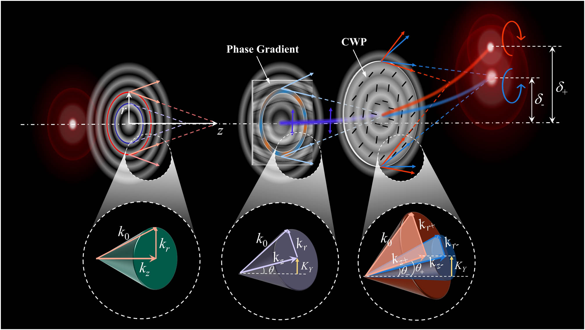
In this work, we demonstrate that a tilted Bessel beam passing through the CWP can perform an analog off-axis CB in free space. The two spin states of the tilted beam gradually separate from each other, of which the separation is proportional to the tilting angle, and much larger than that of the traditional PSHE. However, it is still too tiny to be accurately measured. By introducing the nonlinear propagation trajectory of the input beam (see Fig. 1), we show that the spin-dependent separation is greatly enhanced. Amazingly, this enhanced PSHE is also applicable to the other Bessel-like beams with nonlinear trajectories that have been reported [42,43]. Our results might contribute to the enrichment of the theory in spin photonics and promote the development of techniques and applications in light field manipulation.
Figure 1.Schematic of the realization of analog off-axis circular birefringence of the Bessel beam.
A. Analog Off-Axis Circular Birefringence of Bessel Beam
The CWP is a typical PB phase element, which is equivalent to a half-wave plate with nonuniform fast axis. Similar to other PB phase elements such as -plate [22,44,45], the CWP has a different optical axis distribution. We previously have realized the axial CB by using a CWP [41]. For a Bessel beam , it can be considered a wave packet with phase velocity in free space. Here, (, , ) denote the cylindrical coordinates, is the wave vector, and and denote the transverse and longitudinal wave vectors, meeting . To realize the axial CB, we input a Bessel beam into the CWP in the normal incidence condition. The transverse wave vectors of the two spin states of the Bessel beam are changed from to , respectively. Correspondingly, the axial wave vectors are changed from to , inducing a phase velocity difference between the two spin states.
For a tilted input Bessel beam , , the spin-dependent bifurcation of transverse wave vectors () will lead to the difference of the propagation direction between the two spin states, which can be visually understood from the evolution of the conical wave vector of the Bessel beam as shown in the bottom of Fig. 1. It is important to note that the tilt angle of the input Bessel beam cannot be too large, or the symmetry of the wave vector cone and the CWP would be mismatched strongly, leading to the serious distortion of the beam. Thus, we will only discuss the paraxial case in the following. By attaching the tilting phase to a Bessel beam, the conical wave vector (green cone) is rotated to an angle (purple cone). When the longitudinal wave vectors of the two spin states are changed to , the tilting angles of the two spin states are , where the signs “+” and “−” correspond to the right- and left-handed spin states, or and values of the Stokes parameter , respectively. This mechanism exactly matches with that of the traditional birefringence of light at medium interface.
For quantitative analysis, we focus on the offset of the mainlobe of the Bessel beam. The offset of the tilted Bessel beam is . Under the paraxial approximation (), it can be expressed as
After passing through the specifically designed CWP [41], of which the local axis orientation is conically distributed (see Fig. 1), the two spin states of the beam obtain inverse additional PB phases , and the corresponding transverse wave vectors are changed to , respectively. Thus, the offsets of the two spin states become
From the above equation, we can get the separation distance between the two spin states, written as
It can be obviously seen from Eq. (3) that the two spin components of the Bessel beam gradually separate from each other, and the separation is proportional to the radial frequency of CWP (), transverse wave vector of Bessel beam (), and tilted phase gradient ().
To verify the above theoretical predictions, we employ the experiment setup as shown in Fig. 2(a). A collimated linearly polarized laser beam (He–Ne laser, 632.8 nm) is transformed into a tilted Bessel beam by a phase modulation loaded on the phase-type spatial light modulator (SLM) combined with a system, and then it passes through the CWP. The CWP is put at the back focal plane of the system, of which the center is carefully matched to that of the Bessel beam. A CCD camera set on a linear micro-displacement stage is used to observe the propagation process of the output field step by step. A combination of a QWP and a polarizer can be inserted to measure the corresponding Stokes parameters. The CWP with the radial frequency π is fabricated via liquid crystal with the photoalignment technique [46–48], which is based on the sulfonic azo-dye SD1 and the dynamic micro-lithography system. Figure 2(b) shows the photograph and the micrograph of the liquid crystal CWP, manifesting the optical axis orientation due to the birefringence of liquid crystals. The diffraction efficiency of the fabricated CWP is measured as .
Figure 2.(a) Experimental setup. Laser, He–Ne laser of wavelength 632.8 nm; P, polarizer; BE, beam expander; SLM, spatial light modulator; BS, beam splitter; L, lens; QWP, quarter-wave plate. (b) Photograph and micrograph of the CWP.
Figure 3(a) shows the theoretical results of the spin separation at different oblique input angle of the Bessel beam during propagation. Here, the transverse wave vector of the Bessel beam is chosen as . Obviously, the separation has a considerable value after a certain propagation distance at a relatively large tilting angle. Considering that the non-diffracting distance of the Bessel beam is limited, the distance for the observation of the spin separation cannot be too far. There is a separation larger than 2 μm at for tilting angle π. However, the spot size of the mainlobe of the resulting beam exceeds 80 μm. By contrast, the spin separation is still too tiny to be distinguished, although it is much bigger than that of the nano level PSHE at the media interface [5–8]. In experiments, we try to qualitatively verify this off-axis CB at the tilting angle π by utilizing the weak measurement [20,21]. Since the linearly polarized Bessel beam passing through the CWP behaves polarization rotating during propagation [41], we perform the postselection by inserting the polarizer , which is rotated to be orthogonal to the polarizations at different distances. The results at different distances are shown in Figs. 3(b)–3(d), where the top and bottom correspond to the simulation and experiment results, respectively. Unfortunately, the separated spin states have a large difference in beam size; thus, the result of postselection shows a ring-shaped profile. As a result, the weak separation cannot be manifested obviously. However, we can still find the effect of the spin separation from these results. With the increase of the propagation distance, the ring tends to become more asymmetric in the separation direction, as also shown by the intensity distribution normalized by the minimum value in the annular region in Fig. 3(e). This indicates that the separation increases with distance. It is important to note that, since the non-diffraction distance of the Bessel beam is limited, we cannot increase the spin separation by continuing to lengthen the propagation distance. From Eq. (3), we can see that the separation can also be increased with the parameters , , and . However, the factors that influence the separation are not independent of each other. For example, increasing and will both shorten the non-diffraction distance of the Bessel beam. Thus, it is hard to observe a more obvious spin separation by changing the parameters. In the experiment, we choose the above parameters and according to the paraxial approximation and the fabrication accuracy of CWP.
Figure 3.Photonic spin Hall effect (PSHE) of tilting Bessel beam passing through a CWP. (a) Theoretical result of the spin separation at different oblique angle; (b)–(d) postselection results of weak measurement; (e) comparison of the experimental results along the vertical dot lines in (b)–(d).
The above PSHE generated by the analog off-axis CB in free space is too tiny to be observed. This tiny effect is mainly due to the tiny influence of on , which can be just enlarged for the on-axis interference [41]. But in the off-axis case, the tiny spin shift cannot be manifested. Fortunately, we find a way to enhance this off-axis shift: using the Bessel-like beam with a nonlinear propagation trajectory, of which the offset has been proven to be obviously influenced by the transverse wave vector [31]. Assuming that the Bessel-like beam propagates along an arbitrary trajectory on the y–z plane, the offset of the mainlobe can be described by a polynomial expansion,
On the basis of our previous works [31,49], this Bessel-like beam can be constructed by attaching a radius-dependent oblique phase on a zeroth-order Bessel beam (see Fig. 1). In paraxial conditions, , and the oblique wave vector can be expressed as
There is a one-to-one relationship between the radius and distance according to the transverse-longitudinal mapping of the Bessel beam [31,49], meeting . Then, we get
After the Bessel-like beam passes through the CWP, the wave vectors are changed from (, ) to (, ), where “+” and “−” correspond to the right- and left-handed spin components. Then, Eq. (6) can be expressed as where . Correspondingly, the offsets of two spin states become where and represent the amplification ratios for the offset and propagation distance, respectively. The above equation indicates that the CWP induces the different transverse offsets for the two spin states. More importantly, the trajectories of the two spin states can both be approximately considered as the scaled curves of the initial one with the ratio . This reveals perfectly an analog off-axis CB in free space induced by the CWP. Considering the paraxial approximation , we substitute and into Eq. (8) and derive the spin separation with Taylor expansion around the point to quantitatively analyze the magnitude of the offsets, which is expressed as
Obviously for the tilted Bessel beam (), the spin separation is only contributed by the tiny term , while for a Bessel-like beam with nonlinear trajectory (), the separation is mainly induced by the ratio , which is much greater than . Namely, the PSHE would be greatly enhanced by introducing the nonlinear propagation trajectory.
We verify the above prediction with the experimental setup in Fig. 2, where the Bessel-like beams are produced by loading the corresponding phase-type computer generated holograms on the SLM, which is calculated by attaching the phase gradient [ is depicted by Eq. (6)] to the zeroth-order Bessel beam . We choose a typical nonlinear curve as the propagation trajectory of the Bessel-like beam, i.e., the parabolic curve , where the parameters are set as and . The propagation of this Bessel-like beam without the CWP is shown in Appendix A (Fig. 7). The experiment results of the beam passing through the CWP are shown in Fig. 4, where Figs. 4(a)–4(h) depict the output intensity distributions at different distances, with the background color representing the corresponding normalized Stokes parameter . The purple and cyan correspond to the right- and left-handed polarizations, respectively. It can be clearly seen that the two spin states of the Bessel-like beam gradually separate from each other after passing through the CWP. The mainlobes of the two spin states are fully separated at 10 cm. It should be noted that the lobe sizes of the two spin states are dramatically different from each other due to their difference on the transverse wave vectors.
Figure 4.Enhancement of PSHE by introducing a parabolic Bessel-like beam. (a)–(h) Intensity distributions of the light field at different distances, with the normalized Stokes parameter represented by background colors; (i) offsets of the spin states versus propagation distance.
To quantitatively analyze the spin-dependent separation, the offsets of the two spin states and , which are defined as the distances from the initial beam center to the intensity peaks of the mainlobes, are measured step by step every 1 cm. The experimentally measured offsets of the two spin states are shown by the discrete data points in Fig. 4(i), where the gray solid line is the theoretical trajectory curve of the Bessel-like beam, and the red and blue dashed lines denote the theoretical trajectories of right- and left-handed spin states after passing through the CWP, respectively. It can be clearly seen that the parabolic Bessel-like beam is split into two parabolic ones, and the increase of the spin separation is accelerated during propagation, i.e., . The measured offsets are in accordance with the theoretical prediction, with an absolute error less than 5 μm, which might be induced by the working accuracy of CWP and the mechanical shift error of the micro-displacement stage. It should be noted that the spin separation rises to nearly 100 μm at , within 200 μm beam offset. At the same distance, the off-axis Bessel beam along a straight line can only be separated in a nanometer scale. These results perfectly demonstrate the enhancement of the PSHE induced by the analog off-axis CB.
C. Controlling the Spin-Dependent Separation via Transverse-Longitudinal Mapping
The transverse-longitudinal mapping of the Bessel beam enables the on-axis points to be modulated independently. In our previous work, we realized the piecewise self-accelerating beam by phase splicing, of which the propagation trajectory was set as a step curve spliced with two different curves [49]. Considering the huge response difference to spin states between linear and nonlinear trajectories, we propose a method to control the spin separation via phase splicing. A typical spliced trajectory consisting of a parabola and a straight line is used to experimentally verify this idea, of which the curve function can be expressed as
We set , , where , , , μ, and . Namely, it is a parabolic trajectory within 7 cm and an inclined straight line after 7 cm, as shown by the red solid line in Fig. 5(i). The phase distribution and the propagation process of this beam are shown in Appendix B (Fig. 8). This type of Bessel-like beam is generated from the SLM in the experimental setup of Fig. 2. After passing through the CWP, the two spin states would behave accelerating separation first and then maintain the separation during the subsequent propagation because of the tiny PSHE of linear trajectory.
Figure 5.Control of PSHE by Bessel-like beam with spliced trajectory. (a)–(h) Intensity distributions with represented by background colors; (i) offsets of the different spin states versus propagation distance; (j) spin separation after 10 cm.
The experiment results are shown in Fig. 5, where Figs. 5(a)–5(h) display the intensity distributions with the background color representing the distributions of . It can be seen that the mainlobes of the two spin states are separated obviously at first [Figs. 5(a)–5(d)], achieving the maximum separation at about 10 cm [Fig. 5(e)]. Then, the separation almost stops increasing, and the two spin states move away from the axis at the same rate [Figs. 5(e)–5(h)]. Figure 5(i) shows the experimentally measured offsets of the two spin states and the theoretically pre-designed curves. The measured offsets match well with the pre-designed trajectories. Notably, the spliced trajectory is separated into two with different spin states. According to Eq. (8), the trajectories of the two spin states are also the spliced ones by scaling the initial trajectory with ratios , and the turning position of the curve is separated from 7 cm to about 4.3 cm and 9.6 cm, respectively. To verify the spin states have stopped separating after the turning position, we further analyze the spin separation as shown in Fig. 5(j). It can be seen that the separation approximately maintains a constant μ. This proves that the further separation of spin states ceases effectively.
It is important to emphasize that the proposed method for the spliced trajectory has more flexibility in controlling the PSHE. We can even transform the PSHE to the axial CB after a certain propagation distance by elaborately designing the trajectory of the input Bessel-like beam (see Appendix C).
D. Extending to Other Bessel-like Beams with Nonlinear Trajectories
Although the above enhanced PSHE is realized mainly based on the Bessel-like beams with the nonlinear propagation trajectory we previously provided [31,49], it can also be extended to other self-accelerating Bessel-like beams. To explore this universality, we employ two types of Bessel-like beams generated by engineering the conical bundles of rays [42] and by independently displacing the circular segments of an axicon [43], respectively. The propagation trajectories are chosen as the cosine-like and spiral curves, respectively. We set π (μ, ) in Ref. [42], and , μ, in Ref. [43]. The phase distributions of the beams are shown in Appendix D (Fig. 10). The experiments for these two Bessel-like beams passing through the CWP are performed with the setup of Fig. 2, and the propagation processes are demonstrated clearly by Visualization 1 and Visualization 2. These two beams both behave in obvious PSHE, where the two spin states separate from each other and propagate on different orbits with different speeds. Figure 6 shows the experimentally measured offsets of the two spin states by comparing them to the theoretically pre-designed curves. The measured offsets match the theoretical curves on the whole, except for some errors due to the diffraction effect of the left-handed spin states with large displacement [31]. Actually, the trajectories of the spin states are also the scaling of the trajectory of input Bessel-like beams. Moreover, this PSHE can also be produced for the higher-order Bessel-like beams with nonlinear trajectories (see Fig. 11, Appendix E). Since the proposed PSHE can be widely extended to Bessel-like beams, we expect that it could be applied in imaging enhancement according to the edge detection with PSHE [36] and the point-spread function engineering by using Bessel beams [50].
Figure 6.Enhanced PSHE induced by different self-accelerating Bessel-like beams. (a) Bessel-like beam along a cosine-like curve in Ref. [42]; (b) spiral Bessel-like beam in Ref. [43].
Figure 7.Parabolic Bessel-like beam. (a) Amplitude distribution of input Bessel beam; (b) phase gradient attached to the input beam; (c) side view of the simulated propagation process, with the pre-designed trajectory marked by the blue dashed line.
Figure 8.Bessel-like beam with a spliced trajectory. The input amplitude is the same as Fig. 7(a). (a) Phase gradient attached to the input beam, where the white dashed line marks the boundary of the two phase gradients, corresponding to the trajectories at different distances, respectively; (b) side view of the simulated propagation process, with the pre-designed trajectory marked by the blue dashed line.
At last, it is necessary to state that the phenomenon of spin-dependent separation in this paper is classified as PSHE, even though some readers may disapprove. The PSHE is regarded as an analogy to the SHE in electronic systems and generally explained by the spin–orbit interaction of photons. In this work, the PB phases of the CWP change the wave vector cones of two spin states, which indirectly change the longitudinal phase speed of the wave packets. It is a typical interaction between the spin angular momentum with the extrinsic orbital angular momentum [41]. For an off-axis Bessel beam, the different phase speeds would induce a transverse separation of spin states, resembling the off-axis CB, while for a self-accelerating Bessel-like beam, its conical wave vector is still related to the transverse wave vector. The spin–orbit interaction mediated by the CWP can induce a similar spin-related wave vector bifurcation, changing the propagation trajectories of the two spin states. We think these results meet the definition of PSHE. We emphasize that this work provides a broadly suitable method for flexibly controlling the spin states, whether it is accepted as the PSHE or not.
3. CONCLUSION
In summary, we have theoretically and experimentally studied the analog off-axis CBs in the free space of Bessel beams passing through a conical-type PB phase element. For the tilted zeroth-order Bessel beam, the off-axis CB could induce the PSHE. We first qualitatively demonstrate the existence of the tiny spin separation or PSHE by weak measurement. By introducing the nonlinear propagation trajectories, the PSHE can be greatly enhanced. More surprisingly, the trajectories of the two separated spin states are the scaling of the initial nonlinear trajectory, representing the analog CB of Bessel-like beams. This enables us to flexibly control the spin-dependent separation by elaborately designing the propagation trajectory. In addition, the enhanced PHSE has been also demonstrated in other self-accelerating Bessel-like beams produced with different mechanisms, including the higher-order Bessel-like beams. We hope our results might contribute to the enrichment of the theory in spin photonics and promote the development of techniques and applications in light field manipulation.
APPENDIX A: PARABOLIC BESSEL-LIKE BEAM
The parabolic Bessel-like beam is generated using the method in our previous work [49]. Figure 7 shows the intensity and phase distributions of the input Bessel-like beam [Figs. 7(a) and 7(b)], and the side view of the propagation process.
APPENDIX B: BESSEL-LIKE BEAM WITH A SPLICED TRAJECTORY
To generate the Bessel-like beam with a spliced trajectory, we use the pure phase modulation [49] and set the propagation trajectory as a step curve. Figure 8 shows the phase gradient and the side view of the propagation process.
APPENDIX C: TRANSFORM THE PSHE TO THE AXIAL CB
Based on controlling the spin-dependent separation via spliced trajectory in Fig. 5, we present a possibility to transform the PSHE to the axial CB after a certain propagation distance. We design the trajectory of the input Bessel-like beam as πand we set μ, , and . Namely, it is a sine-like trajectory within 12 cm and an axial straight line after 12 cm, as shown by the gray line in Fig. 9(a). Figure 9(a) shows the simulated propagation process in the y–z plane after passing through the CWP. We can obtain the trajectories of the two spin states by combining the Eq. (8) in the main text and the Taylor expansion of the pre-designed trajectory. The theoretical trajectories of two spin states are shown by the blue and red dashed lines in Fig. 9(a). We can find that the spin-dependent trajectories match well with the pre-designed lines. More importantly, the two spin states could be merged again and maintain a stable axial superposition. The merged beam represents the polarization rotation on the axis, with about 3.3 cm period [see Figs. 9(b)–9(e)].
Figure 9.Simulation results of transforming the PSHE to the axial CB. (a) Side view of the simulated propagation process; (b)–(e) intensities of the beam passing through two orthogonal analyzers during stable axial CB (after 20 cm), where the double-arrows denote the orientations of analyzers.
Figure 11.Simulation results of the PSHE of parabolic first-order Bessel-like beam. (a)–(d) Intensity distributions of the beam at different distance; (e) offsets of the different spin states versus propagation distance.
APPENDIX D: PHASE OF THE COSINE AND SPIRAL BESSEL-LIKE BEAMS
Figure 10 shows the phase distributions of the beams generated by engineering the conical bundles of rays [42] and by independently displacing the circular segments of an axicon [43], respectively.
APPENDIX E: PSHE OF A HIGHER-ORDER BESSEL-LIKE BEAM WITH NONLINEAR TRAJECTORY
To verify that the proposed enhanced PSHE is also applicable to the higher-order Bessel-like beam, we choose the input beam as attaching the phase gradient in Fig. 7(b). After passing through the CWP, this beam also divides into two spin states with different trajectories, as shown in Figs. 11(a)–11(d). Figure 11(e) depicts the trajectories of the central dark cores of the input beam without CWP and the two spin components after CWP.