
Tao Xu, Tianyu Gao, Yanze Wang, Wenhao Li, Wei Li, Cheng Du, Zhiqun Yang, Yaping Liu, Lin Zhang. High-gain integrated in-line few-mode amplifier enabling 3840-km long-haul transmission[J]. Photonics Research, 2022, 10(12): 2794
- Photonics Research
- Vol. 10, Issue 12, 2794 (2022)
Fig. 1. Long-haul MDM transmission over a 3MF with in-line 3M-EDFAs.
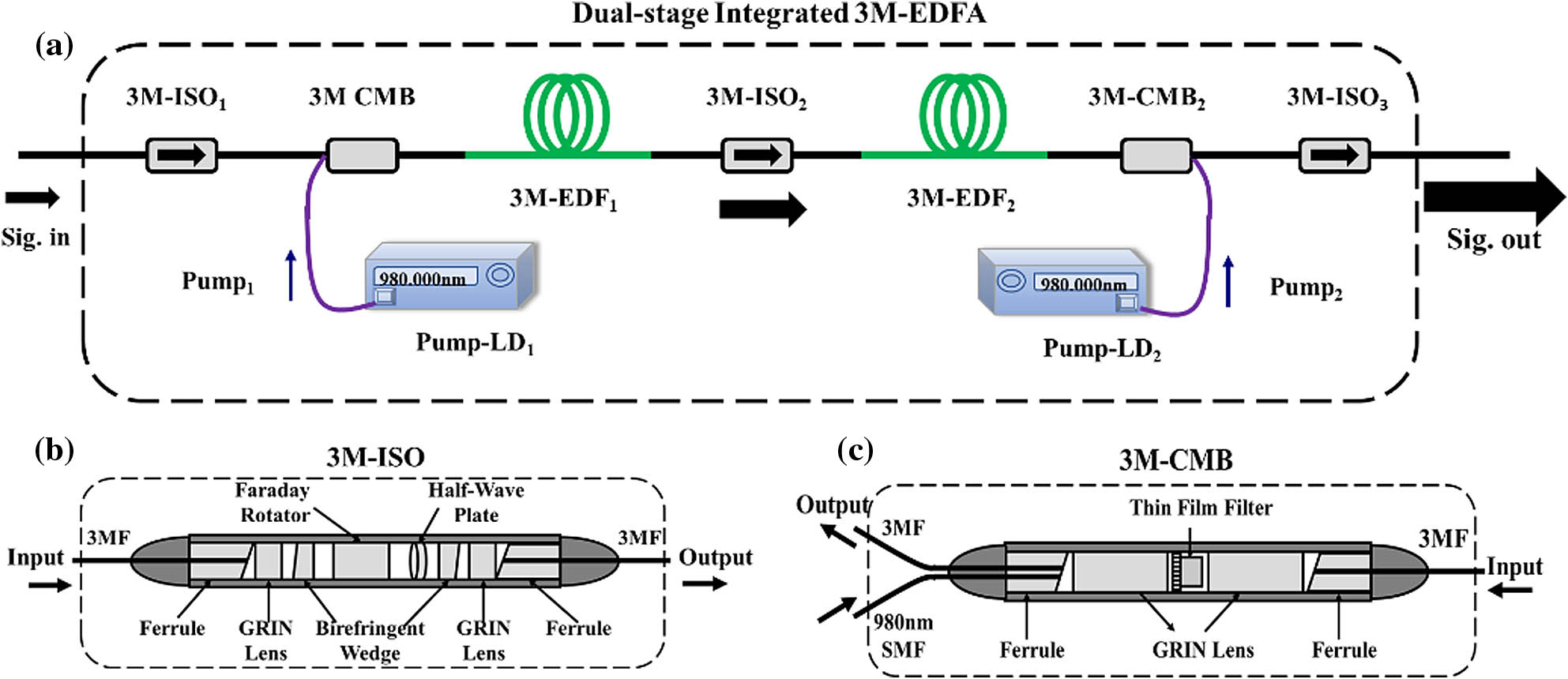
Fig. 2. Schematic of (a) the dual-stage integrated 3M-EDFA, (b) 3M isolator (3M-ISO), and (c) 3M power combiner (3M-CMB).
Fig. 3. (a) Refractive index profile and (b) normalized erbium doping profile of the 3M-EDF; square points are measured results and the solid black line is a fitted curve.
Fig. 4. (a) Experimental setup for characterizing the proposed 3M-EDFA, (b) the near-field modal patterns of input and output signals, and (c) crosstalk matrix of the whole setup.
Fig. 5. Modal gain and NF of a single-stage 3M-EDFA as a function of 3M-EDF length.
Fig. 6. (a) The modal gain, DMG, and (b) NF of the 3M-EDFA as a function of forward pump power for the first stage.
Fig. 7. (a) The modal gain, DMG, and (b) NF of the 3M-EDFA as a function of backward pump power for the second stage.
Fig. 8. (a) The modal gain, DMG, (b) output signal power, and NF of the 3M-EDFA as a function of input power.
Fig. 9. (a) Modal gain, DMG, (b) NF, and output power of the proposed 3M-EDFA as a function of wavelength.
Fig. 10. Experimental setup for the MDM transmission over 3840-km 3MF with the proposed 3M-EDFA.
Fig. 11. (a) The amplitude of impulse responses at 1344 km; (b) the averaged impulse responses and its fitting curves at 1344 km, 2688 km, and 3840 km; (c) constellations; and (d) MDL values of the three modes after transmission.
|
Table 1. Insertion Losses of the Integrated 3-Mode Components
|
Table 2. Insertion Losses of the Passive Few-Mode Components

Set citation alerts for the article
Please enter your email address
© Copyright 2018-2021 | Chinese Laser Press. All Rights Reserved 沪ICP备15018463号-20