1Key Laboratory of Opto-electronic Information Technology of Ministry of Education and Tianjin Key Laboratory of Integrated Opto-electronics Technologies and Devices, School of Precision Instruments and Opto-electronics Engineering, Tianjin University, Tianjin 300072, China
2FiberHome Telecommunication Technologies Co., Ltd., Wuhan 430205, China
An integrated few-mode erbium-doped fiber amplifier (FM-EDFA) with high modal gain is suitable for the in-line amplification in mode-division multiplexing transmission (MDM) systems. We first experimentally demonstrate a dual-stage integrated FM-EDFA supporting three linear polarization modes. Consisting of integrated passive components with low insertion losses, the FM-EDFA has a similar structure and performance to widely used commercial single-mode EDFAs. The averaged modal gain of 25 dB, the differential modal gain (DMG) of , and noise figures of 5–7 dB are simultaneously achieved. In addition, the DMG of the 3M-EDF itself is . Moreover, an MDM transmission experiment with the in-line few-mode amplification by our proposed FM-EDFA over a 3840-km few-mode fiber link for a 28-Gbaud quadrature phase-shift keying (QPSK) signal is demonstrated.
1. INTRODUCTION
Mode-division multiplexing (MDM) technology utilizing few-mode fibers (FMFs) has been extensively investigated as a promising approach to overcome the capacity crunch in high-speed and long-haul systems based on single-mode fibers [1–4]. Not only for breaking the capacity limit, MDM is also expected to mitigate the quick scaling up in power consumption by optical amplification over a long-haul, especially in submarine and fiber link. In order to realize the power saving offered by MDM systems, few-mode erbium-doped fiber amplifiers (FM-EDFAs) that simultaneously amplify multiple spatial channels are desired [5]. It is critical for FM-EDFAs to have a low differential modal gain (DMG) originated from the difference in the overlaps among the signal profile, pump mode profile, and erbium-doped distribution, as the DMG significantly affects the transmission distance and capacity [6]. Some studies have demonstrated that modal gain equalization is realized by reconfiguring the erbium-doping profile [7–10], pump modal configuration [11–14], and index profile [15]. However, the FM-EDFAs in the above schemes cannot support spatial modes, as design and fabrication become more complex with the increase of spatial modes. Furthermore, a cladding-pumped configuration is another approach applied in 6-mode, 10-mode, and 21-mode EDFAs [16–18], but the DMG is hard to reduce to . In addition, a strongly coupled FM-EDFA realized by distributed long-period gratings has been reported with a DMG of 1.1 dB [19], but it still needs the experiment to validate its practicability. Although, in Ref. [15], a DMG of has been experimentally demonstrated in a ring-core FM-EDFA with a photonic lantern as the power combiner, it is important to note that auxiliary passive components, as isolators and power combiners, contribute to the DMG.
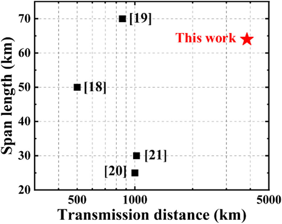
Several MDM transmission systems over FMFs, amplified by in-line FM-EDFAs, were demonstrated, as outlined in Fig. 1 [20–23]. In addition, Raman amplification and parallel single-mode EDFAs are also available in long-haul transmission systems using 3MF [24,25]. In Ref. [20], a cladding-pumped FM-EDFA affords the optical loss of a 70-km FMF, but the DMG of limits the transmission distance of . In the remaining experiments, the core-pumped FM-EDFAs with a low averaged modal gain limit the span length of FMF links to . Thus, another key factor for FM-EDFAs is to offer the high modal gain. Moreover, most of the core-pumped FM-EDFAs are implemented with numerous bulky free-space components, which not only lack stability and flexibility, but also are expensive and suffer from a high coupling loss. In addition, from the viewpoint of MDM’s commercialization, integrated FM-EDFAs are highly economical [3,26–28]. It would be highly desirable to design an integrated high-gain and low-DMG FM-EDFA for the in-line few-mode amplification in long-haul MDM systems.
Figure 1.Long-haul MDM transmission over a 3MF with in-line 3M-EDFAs.
In this paper, for the first time, we experimentally demonstrate a high-gain dual-stage integrated three-mode EDFA (3M-EDFA) with 980-nm core pumping. Integrated three-mode isolators and three-mode power combiners with the insertion loss of and mode-dependent loss (MDL) of 0.3 dB are used to construct an integrated 3M-EDFA. The three-mode erbium-doped fiber (3M-EDF) is designed with two-layer erbium doping distribution to realize low DMG. Importantly, the test results show that the averaged modal gain of 25 dB, the DMG of , and noise figures (NFs) of 5–7 dB across the C-band are realized based on our proposed 3M-EDFA. The DMG of the 3M-EDF itself is . The high-gain and low-DMG integrated 3M-EDFA is suitable for in-line amplification in long-haul MDM transmission systems. Consequently, we first demonstrate a 28-Gbaud quadrature phase-shift keying (QPSK) transmission with the in-line few-mode amplification based on our proposed 3M-EDFA over a 3840-km three-mode fiber link.
Sign up for Photonics Research TOC. Get the latest issue of Photonics Research delivered right to you!Sign up now
2. PRINCIPLE OF THE INTEGRATED 3M-EDFA
Figure 2(a) shows the schematic of the proposed high-gain dual-stage fiberized 3M-EDFA, which is constructed by three 3M isolators, two 3M power combiners, two pieces of 3M-EDFs, and two 980-nm pump laser diodes (LDs). The first stage of the amplifier is viewed as a low-noise preamplifier, while the second stage can be viewed as a power amplifier. A 3M isolator is used in the middle to prevent the backward amplified spontaneous emission (ASE) returning to the first stage, which otherwise depletes the population inversion at the beginning of the and deteriorates the NF of the whole amplifier. In order to realize low NFs and high gains, forward and backward pumping configurations are applied to the first and the second stages of the amplifier, respectively.
Figure 2.Schematic of (a) the dual-stage integrated 3M-EDFA, (b) 3M isolator (3M-ISO), and (c) 3M power combiner (3M-CMB).
The 3M isolator and 3M power combiner are shown in Figs. 2(b) and 2(c), similar to the single-mode ones in a single-mode EDFA [29,30]. In this type of package, 3MFs and some free-space optical components, such as a graded-index (GRIN) lens, Faraday rotator, and thin-film filter, are mounted in a ferrule sleeve. 3MFs with an 8°-angled end to minimize the reflection are fitted in the ferrule. The GRIN lens is used to collimate the emergent light from the input 3MF and refocus the collimated light into the output 3MF. There are two main structures of the power combiner, including a fused-fiber coupler and thin-film filter-based components. For our integrated 3M power combiner, we prefer the latter solution, in which the thin-film filter is used to simultaneously reflect the pump lights and transmit the signal lights. The mode field diameter and the beam divergence angle of the mode are bigger than that of mode in common 3MF. Therefore, the distance between the GRIN lens and the ferrule and the focal length are important for a low insertion loss. Table 1 lists the insertion losses of those integrated three-mode components. It is clearly seen that the insertion loss of mode is higher in these key passive components.
Insertion Losses of the Integrated 3-Mode Components
Components
(dB)
(dB)
(dB)
0.17
0.52
0.53
0.18
0.49
0.47
0.23
0.56
0.55
0.31
0.54
0.58
0.38
0.48
0.53
The 3M-EDF supporting three linear polarization modes, namely , , and , is fabricated by modified chemical vapor deposition. The core diameter of the 3M-EDF is 16 μm, and its numerical aperture is 0.1. The mode areas of , , and are μ, μ, and μ, respectively. Figure 3(a) shows the refractive index profiles of the designed and fabricated 3M-EDFs, where an index dip at the center appears, but our design is tolerant to it. Moreover, in order to minimize the DMG, the erbium dopant distribution has two layers with a higher doping concentration in the outer layer [9]. The inner and outer layers are and . The designed and fabricated erbium doping profiles are normalized for comparison, as shown in Fig. 3(b). Measured results are obtained by an electron probe micro-analyzer, and the solid black line is a fitted curve based on the measured results. Although the fabricated 3M-EDF has higher erbium ion concentrations than the originally designed values because of fabrication imperfections, it still functions a two-layer profile well. The simulation results show that the DMG of 3M-EDFA with ±5% and ±10% erbium doping concentration errors becomes 0.5 dB and 0.8 dB across the C-band. Hence, gain equalization can be realized with a 980-nm mode pump.
Figure 3.(a) Refractive index profile and (b) normalized erbium doping profile of the 3M-EDF; square points are measured results and the solid black line is a fitted curve.
Figure 4(a) shows the experimental setup to characterize the proposed 3M-EDFA. The input signals of three spatial modes are obtained by simultaneously sending a tunable laser light to a commercial 3M-Mux, based on the multi-plane light conversion technique [31]. 80-m and 160-m single-mode fibers are inserted between the laser and the 3M-Mux to avoid interference among the modes, while three variable optical attenuators (VOAs) are used immediately to adjust the signal powers, together with three polarization controllers placed before the 3M-Mux to ensure the purity of the converted mode. The output 3MF of the 3M-Mux is spliced to the 3M-EDFA. The amplified signals from the proposed 3M-EDFA are demultiplexed to fundamental modes by a 3M-DeMux and then sent to an optical spectrum analyzer (OSA).
Figure 4.(a) Experimental setup for characterizing the proposed 3M-EDFA, (b) the near-field modal patterns of input and output signals, and (c) crosstalk matrix of the whole setup.
The modal crosstalk between the 3M-Mux and 3M-DeMux is . As listed in Table 2, the insertion loss of each mode is about 3 dB for both 3M-Mux and 3M-DeMux, with the MDLs of for both. At the two splicing points, A and B, the insertion losses of the and modes are and , respectively, and the associated MDLs are . The input and output spectra of the 3M-EDFA are recorded by the OSA, respectively. The modal gain and NF are measured by comparing two spectra with the consideration of the device insertion losses and the splice losses. Figure 4(b) shows the near-field modal patterns of the input and output signals, under the condition that individual mode is amplified separately by the 3M-EDFA and by carefully adjusting the polarization of each mode. Before characterizing the gain and NF of the 3M-EDFA, the modal crosstalk of the whole setup should be measured first, because mode coupling among signal modes may lead to measurement errors [32]. The crosstalk matrix in Fig. 4(c) shows that the overall crosstalk is , which will not severely deteriorate signal quality as the multiple-input multiple-output (MIMO) technique can be used to recover the signal [2]. In order to accurately characterize the modal gain, the output signal powers should be corrected according to this matrix [10,32].
Insertion Losses of the Passive Few-Mode Components
Components/Splicing Points
(dB)
(dB)
(dB)
3M-Mux
3.06
3.06
3.11
3M-DeMux
2.89
2.93
2.83
A
0.1
0.2
0.35
B
0.15
0.23
0.41
We first use the cutting-back method to test the optimized length of the 3M-EDF for a low-NF single-stage 3M-EDFA, as the NF of the dual-stage 3M-EDFA is mainly dependent on the NF of the first stage amplifier. Figure 5 shows the modal gain and NF of the fundamental mode at different EDF lengths with a forward pumping power of 600 mW and the input signal power of . The length is ranging from 3.5 to 6 m with the step of 0.5 m. The lowest NF occurs at 4 m, very slightly smaller than that at 3.5 m by 0.26 dB, which may be due to experimental fluctuations. Limited by the maximum output power of the pump LD, the modal gain starts to saturate at the length of 5.5 m. In order to simultaneously achieve the low NF and high modal gain, the lengths of the 3M-EDF for the first and second stage amplifiers are set to 4 m and 5.5 m, respectively.
Figure 5.Modal gain and NF of a single-stage 3M-EDFA as a function of 3M-EDF length.
Figure 6 shows the modal gain, DMG, and NF as a function of forward pump power (PP1) in the first stage when the backward pump power (PP2) in the second stage is set to 600 mW and the input signal power for each mode is . PP1 ranges from 125 to 625 mW with the step of 100 mW. The DMG and NF decrease as the PP1 increases, while the modal gain almost starts to saturate with a PP1 of 200 mW. The lowest NFs are 4.72 dB, 5.62 dB, and 6.51 dB for , , and with the PP1 of 625 mW. The higher NFs for modes are because of the higher erbium ion concentration in the outer layer of the 3M-EDF, which leads to a higher ASE power in the modal group. Furthermore, the NF difference between and partly originates from the MDL of the integrated passive devices. Figure 7 shows the modal gain, DMG, and NF as a function of PP2 when the PP1 is set to 625 mW. The maximum modal gains of , , and are 25.59 dB, 24.52 dB, and 24.43 dB, respectively, with the minimum DMG of 1.16 dB when the PP2 is set to 600 mW. A larger modal gain and a lower DMG can be achieved if the pump LD with a larger output power is available. Moreover, the NF of each mode is almost unchanged with the aid of a 3M isolator between two stages, which prevents the backward ASE power returning into the first-stage amplifier. Hence, we can observe that the dual-stage amplifier structure is an effective technique to realize high gain and low NF for the FM-EDFA, which is crucial in a long-haul transmission.
Figure 6.(a) The modal gain, DMG, and (b) NF of the 3M-EDFA as a function of forward pump power for the first stage.
Figure 8 shows the modal gain, DMG, NF, and the overall output signal power as a function of the input power. The 3M-Mux and 3M-DeMux are used to characterize the performance of each mode, which does not influence the amplification performance in practice and output power of the 3M-EDFA in transmission systems. The input power ranges from to for each mode. While the input power is , the modal gain of is achieved. In addition, the DMG can reach 0.26 dB and NFs for the three modes are 5.06 dB, 5.27 dB, and 5.4 dB when the input power of each mode is , which shows an equalized effect for both modal gain and NFs. The reason for this phenomenon is probably due to a larger mode crosstalk level in the small input power regime. The overall output signal power reaches 20.69 dBm, which shows a potential application for the large saturation output power of the FM-EDFA, which is a key factor when the wavelength-division multiplexing schemes are considered.
Figure 8.(a) The modal gain, DMG, (b) output signal power, and NF of the 3M-EDFA as a function of input power.
Figure 9(a) shows gain and DMG across the C-band, where a flattened ASE is used as the signal source. If the ASE source is used as the input source, the setup’s crosstalk performance degrades <−5 dB, which has little influence on the performance test and applications in the strongly-couped MDM transmission systems. PP1 and PP2 are 625 mW and 600 mW, respectively. The total input signal power of each mode is . One need to differentiate amplification performance provided by an EDF or an amplifier as a whole. Here, we find that a DMG of for the 3M-EDF itself by subtracting the MDL of all passive devices from the DMG of the 3M-EDFA is obtained over the C-band. The averaged modal gain of the amplifier across the C-band is and the DMG is . The modal gain ripple is across the C-band, which could be reduced if few-mode gain flattening-filters are available. Figure 9(b) shows the NF across the C-band, where eight equalized signals with a total power of are selected from the ASE source as the input source. The amplified output power spectrum is shown in the inset of Fig. 9(b), which has a similar trend to the gain spectrum in Fig. 9(a). The NFs of and modes are and , respectively. Meanwhile, the overall performance of gain and NF can be further improved if passive devices with a lower insertion loss and MDL are available.
Figure 9.(a) Modal gain, DMG, (b) NF, and output power of the proposed 3M-EDFA as a function of wavelength.
4. MDM TRANSMISSION BASED ON THE 3M-EDFA OVER 3840-km 3MF
To verify the practicality of the 3M-EDFA, we construct a recirculating three-mode loop system, as shown in Fig. 10. An external cavity laser with a linewidth of 100 kHz operating at 1532 nm is modulated with 28-Gbaud QPSK signal. The modulated signal is split into three tributaries, decorrelated with the length of delay lines of 400 m and 800 m for and . The 3M-EDFA, as an in-line amplifier, is used to compensate the loop transmission losses from 64-km 3MF, 3M-Mux, 3M-DeMux, acousto-optic modulator, and VOA. The measured differential mode delay (DMD), fiber loss, and total MDL of the 3MF are , , and , respectively. The lunch power of each mode is 4 dBm. A cyclic mode permutation scheme is applied to suppressed DMD-induced pulse spreading [25]. Three output signals are received by coherent receivers and digitized by real-time oscilloscopes operating at 80 GSa/s. Then the frequency-domain 3 × 6 MIMO equalization with 4096 taps is used to recover the data.
Figure 11.(a) The amplitude of impulse responses at 1344 km; (b) the averaged impulse responses and its fitting curves at 1344 km, 2688 km, and 3840 km; (c) constellations; and (d) MDL values of the three modes after transmission.
Figure 11(a) shows the amplitude of equalizer responses at 1344 km. The responses become bell-shaped as the sufficient mode exchanges, rather than still having many spikes. The averaged responses and their fitting curves at 1344 km, 2688 km, and 3840 km are shown in Fig. 11(b). The corresponding response widths are 50.03 ns, 72.99 ns, and 90.13 ns, respectively. Figures 11(c) and 11(d) show the bit error rate (BER) and MDL as a function of the transmission distance. In addition, symbols are captured for BER calculation. After 3840-km transmission, the averaged BER over three modes of is reached, with that of each mode below the forward error correction limit [33]. Due to the polarization drift of the amplifier, there are some fluctuations in received signals. This might explain why the BER obtained at 3840 km is lower than at 3456 km. The MDL is estimated from the singular values of three modes based on the singular-value decomposition of the channel matrix. A 10-dB MDL is observed after 3840-km transmission which also contains a pair of modal multiplexers and some splicing points. Such a large MDL has become an important restricting factor for the longer transmission distance. Even so, it is possible for our high-gain integrated 3M-EDFA to support a span length of . To the best of our knowledge, the total transmission distance of 3840 km represents the longest transmission distance among all the existing MDM transmission systems with in-line FM-EDFAs.
5. CONCLUSIONS
For the first time, we have experimentally demonstrated an in-line high-gain integrated 3M-EDFA in a long-haul MDM transmission system over 3MF. Integrated 3M isolators and 3M power combiners with an insertion loss of and MDL of 0.3 dB are constructed, which leads to the integrated 3M-EDFA similar to widely used single-mode EDFAs. Importantly, the averaged modal gain of 25 dB, DMG of , and low NFs of 5–7 dB over the C-band can be simultaneously achieved by the proposed 3M-EDFA. In addition, the DMG of the 3M-EDF itself is . Based on our high-performance integrated 3M-EDFA as the in-line few-mode amplifier, we experimentally demonstrate a 28-Gbaud QPSK transmission over 3840-km 3MF. After 3840-km transmission, the averaged BER for three modes is , and the MDL value is . The overall output signal power for the proposed FM-EDFA can be further improved with the lager pump power, which indicates a potential application in integrated MDM systems supporting more linear polarization modes and the longer transmission distance.
[8] E. Ip, M.-J. Li, K. Bennett, A. Korolev, K. Koreshkov, W. Wood, C. Montero, J. Liñares. Experimental characterization of a ring-profile few-mode erbium-doped fiber amplifier enabling gain equalization. Optical Fiber Communication Conference (OFC), JTh2A.18(2013).
[15] Y. Jung, Q. Kang, L. Shen, S. Chen, H. Wang, Y. Yang, K. Shi, B. C. Thomsen, R. A. Correa, Z. S. Eznaveh. Few mode ring-core fibre amplifier for low differential modal gain. European Conference on Optical Communication (ECOC), 1-3(2017).
[16] N. K. Fontaine, B. Huang, Z. S. Eznaveh, H. Chen, J. Cang, B. Ercan, A. Veláquez-Benitez, S. Chang, R. Ryf, A. Schulzgen. Multi-mode optical fiber amplifier supporting over 10 spatial modes. Optical Fiber Communication Conference (OFC), Th5A.4(2016).
[17] Y. Wakayama, K. Igarashi, D. Soma, H. Taga, T. Tsuritani. Novel 6-mode fibre amplifier with large erbium-doped area for differential modal gain minimization. 42nd European Conference on Optical Communication (ECOC), 1-3(2016).
[19] Y. Liu, X. Wang, Z. Yang, L. Zhang, G. Li. Strongly coupled few-mode erbium-doped fiber amplifiers with ultralow differential modal gain. Optical Fiber Communications Conference and Exhibition (OFC), 1-3(2020).
[21] N. Cvijetic, E. Ip, N. Prasad, M.-J. Li, T. Wang. Experimental time and frequency domain MIMO channel matrix characterization versus distance for 6 × 28 Gbaud QPSK transmission over 40 × 25 km few mode fiber. Optical Fiber Communication Conference, Th1J.3(2014).
[23] R. Ryf, N. K. Fontaine, H. Chen, A. Gnauck, Y. Jung, Q. Kang, J. Sahu, S. Alam, D. Richardson, Y. Sun. 72-Tb/s transmission over 179-km all-fiber 6-mode span with two cladding pumped in-line amplifiers. European Conference on Optical Communication (ECOC), 1-3(2015).
[33] D. A. Morero, M. A. Castrillon, F. A. Ramos, T. A. Goette, O. E. Agazzi, M. R. Hueda. Non-concatenated FEC codes for ultra-high speed optical transport networks. IEEE Global Telecommunications Conference-GLOBECOM, 1-5(2011).