• Acta Optica Sinica
  • Vol. 43, Issue 9, 0904001 (2023)
Mingdeng Hu*, Xiong Xiong**, Jianle Wu, Yu Duan, Yu Du, and Jianhong Mao
Author Affiliations
  • Zhejiang Juexin Microelectronics Co., Ltd., Lishui 323000, Zhejiang , China
  • show less
    DOI: 10.3788/AOS221704 Cite this Article Set citation alerts
    Mingdeng Hu, Xiong Xiong, Jianle Wu, Yu Duan, Yu Du, Jianhong Mao. Design of Cold Shield in Infrared Detector[J]. Acta Optica Sinica, 2023, 43(9): 0904001 Copy Citation Text show less
    Lightpath of optical system off-axis point imaging
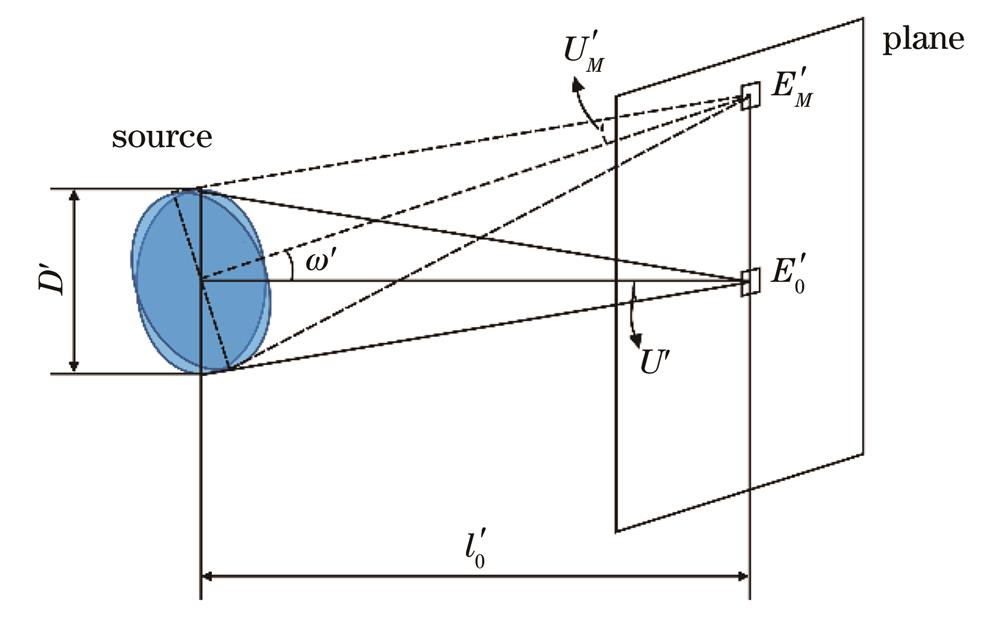
    Fig. 1. Lightpath of optical system off-axis point imaging
    Optical analysis model of infrared detector
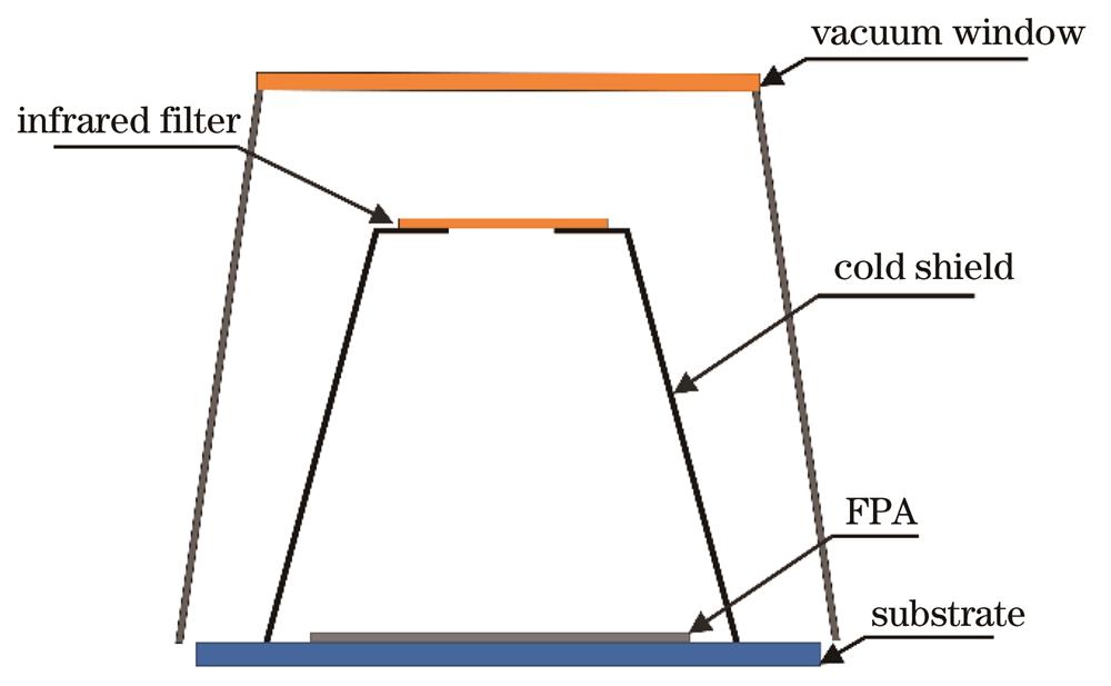
    Fig. 2. Optical analysis model of infrared detector
    Height and uniformity distribution of cold shield. (a) Maximum response and temperature gradient curves in the focal plane of cold shield; (b) uniformity distribution in the focal plane
    Fig. 3. Height and uniformity distribution of cold shield. (a) Maximum response and temperature gradient curves in the focal plane of cold shield; (b) uniformity distribution in the focal plane
    Four designed structures for cold shield. (a) Tower type; (b) accordion type; (c) straight cylinder type; (d) inverted cone type
    Fig. 4. Four designed structures for cold shield. (a) Tower type; (b) accordion type; (c) straight cylinder type; (d) inverted cone type
    PST curves of four cold shield structures at different F numbers. (a) F1.2; (b) F2; (c) F3; (d) F4; (e) F5.5
    Fig. 5. PST curves of four cold shield structures at different F numbers. (a) F1.2; (b) F2; (c) F3; (d) F4; (e) F5.5
    Sidewall venting structure and radiation distribution. (a) Sidewall venting; (b) path of stray radiation; (c) radiation of sidewall venting
    Fig. 6. Sidewall venting structure and radiation distribution. (a) Sidewall venting; (b) path of stray radiation; (c) radiation of sidewall venting
    Improved venting structures and radiation distribution. (a) Top venting; (b) countersunk venting; (c) step venting; (d) top venting radiation; (e) countersunk venting radiation; (f) step venting radiation
    Fig. 7. Improved venting structures and radiation distribution. (a) Top venting; (b) countersunk venting; (c) step venting; (d) top venting radiation; (e) countersunk venting radiation; (f) step venting radiation
    Optical component

    Absorptance /

    %

    Reflectivity /

    %

    Transmittance /

    %

    Window frame01000
    Vacuum window0595
    Infrared filter0595
    Cold shield inner surface9730
    Table 1. Surface property parameters of optical analysis model
    Shield structureF1.2F2F3F4F5.5
    Tower type
    Accordion type
    Straight cylinder type
    Inverted cone type
    Table 2. Selection of cold shield structure under different F numbers
    Main radiating surfaceTemperature /KRadiating surface area /mm2Radiated power /W
    Window frame inner surface3002830.740.0112
    Vacuum window300633.050.0025
    Table 3. Radiation of main surface inside the detector
    Mingdeng Hu, Xiong Xiong, Jianle Wu, Yu Duan, Yu Du, Jianhong Mao. Design of Cold Shield in Infrared Detector[J]. Acta Optica Sinica, 2023, 43(9): 0904001
    Download Citation