
Sun-Goo Lee, Seong-Han Kim, Chul-Sik Kee. Band dynamics accompanied by bound states in the continuum at the third-order Γ point in leaky-mode photonic lattices[J]. Photonics Research, 2021, 9(6): 1109
- Photonics Research
- Vol. 9, Issue 6, 1109 (2021)
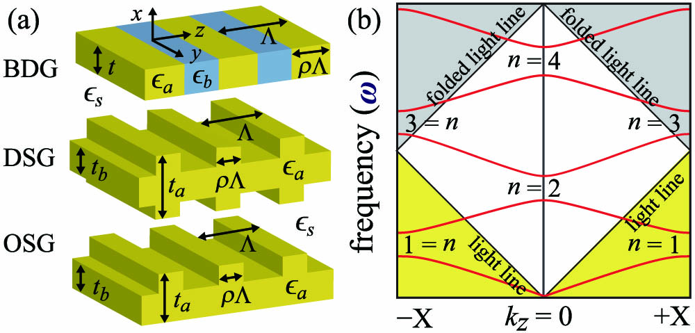
Fig. 1. (a) Schematics of the representative 1D photonic lattices for studying the fourth stop band. (b) Conceptual illustration of the photonic band structures including the first four band gaps. Guided waves are described by the complex frequency Ω = ω − i γ γ
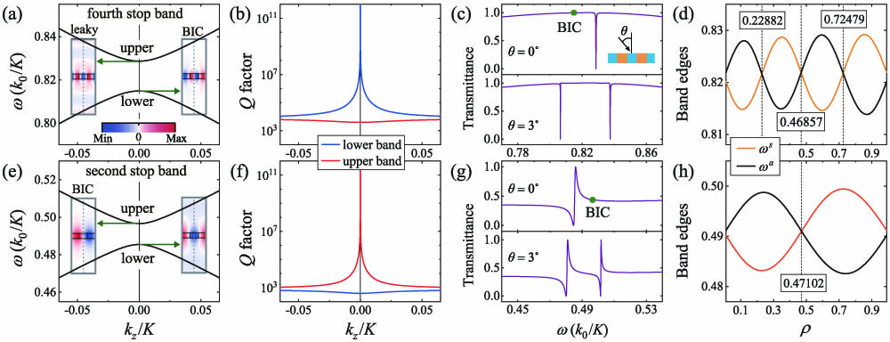
Fig. 2. Comparison between the key properties of the fourth (a)–(d) and second (e)–(h) stop bands. (a), (e) Simulated dispersion relations; (b), (f) radiative Q ρ E y ρ ϵ 0 = 9.00 Δ ϵ = 2.00 ϵ s = 1.00 t = 0.20 Λ ρ = 0.35
Fig. 3. Simulated dispersion relations near the third-order Γ ϵ 0 + ϵ 1 cos ( K z ) ϵ 0 + ϵ 2 cos ( 2 K z ) ϵ 0 + ϵ 3 cos ( 3 K z ) ϵ 0 + ϵ 4 cos ( 4 K z ) ϵ 0 + ϵ 5 cos ( 5 K z ) 2 .
Fig. 4. FEM-simulated spatial electric field distributions at the upper and lower bands of Δ Ω 4 ϵ 4 = ( Δ ϵ / 2 π ) sin ( 4 π ρ )
Fig. 5. (a) Simulated leaky edge Q ρ Q ϵ 0 + ϵ 1 cos ( K z ) ϵ 0 + ϵ 2 cos ( 2 K z ) Q k z ρ = 0.46909 ρ = 0.47
Fig. 6. Simulated dispersion relations at the closed band states in the vicinity of the third-order Γ ρ = 0.46857 ρ = 0.22882 ρ = 0.72479
Fig. 7. Properties of the DSG structure at the fourth stop band. (a) Simulated dispersion relations and (b) radiative Q Γ θ = 0 ° θ = 3 ° ρ Q ρ Q k z ρ = 0.47307 ρ = 0.47313 ρ = 0.22396 ρ = 0.72591 t 0 = 0.15 Λ Δ t = t a − t b = 0.05 Λ ϵ a = 12.00 ϵ s = 1.00
Fig. 8. Properties of the OSG structure at the fourth stop band. (a) Simulated dispersion relations and (b) radiative Q Γ θ = 0 ° θ = 3 ° ρ Q ρ Q k z ρ = 0.50273 7 .

Set citation alerts for the article
Please enter your email address
© Copyright 2018-2021 | Chinese Laser Press. All Rights Reserved 沪ICP备15018463号-20