• High Power Laser Science and Engineering
  • Vol. 7, Issue 1, 010000e4 (2019)
J. Bromage*, S.-W. Bahk, I. A. Begishev, C. Dorrer, M. J. Guardalben, B. N. Hoffman, J. B. Oliver, R. G. Roides, E. M. Schiesser, M. J. Shoup, M. Spilatro, B. Webb, D. Weiner, and J. D. Zuegel
Author Affiliations
  • Laboratory for Laser Energetics, University of Rochester, Rochester, NY 14623-1299, USA
  • show less
    DOI: 10.1017/hpl.2018.64 Cite this Article Set citation alerts
    J. Bromage, S.-W. Bahk, I. A. Begishev, C. Dorrer, M. J. Guardalben, B. N. Hoffman, J. B. Oliver, R. G. Roides, E. M. Schiesser, M. J. Shoup, M. Spilatro, B. Webb, D. Weiner, J. D. Zuegel. Technology development for ultraintense all-OPCPA systems[J]. High Power Laser Science and Engineering, 2019, 7(1): 010000e4 Copy Citation Text show less
    Top level of the EP OPAL (optical parametric amplifier line) system, showing the major subsystems and the neighboring OMEGA EP beamlines that would be available for joint shots. NOPA, noncollinear optical parametric amplifier; EPTC, OMEGA EP target chamber.
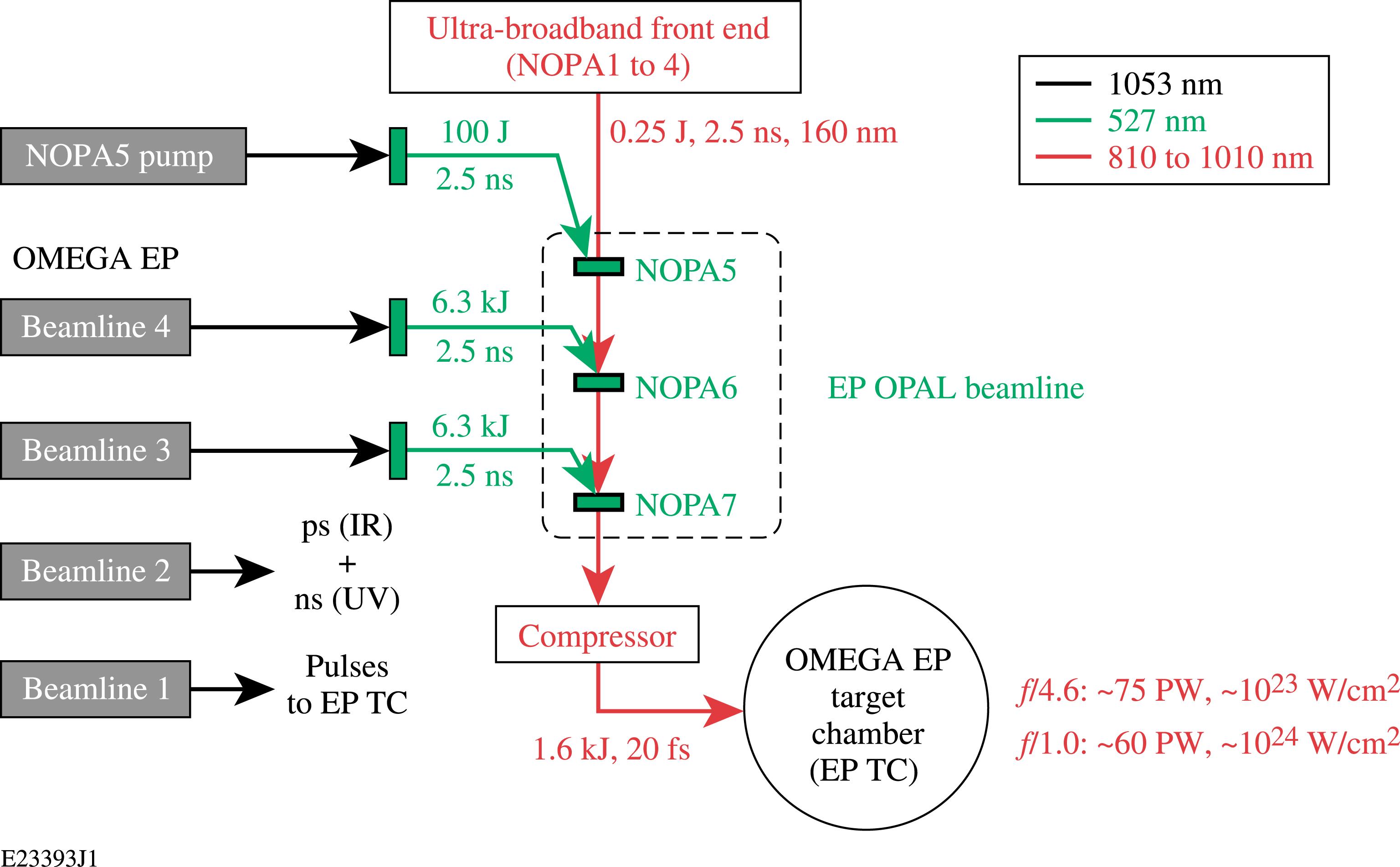
    Fig. 1. Top level of the EP OPAL (optical parametric amplifier line) system, showing the major subsystems and the neighboring OMEGA EP beamlines that would be available for joint shots. NOPA, noncollinear optical parametric amplifier; EPTC, OMEGA EP target chamber.
    Isometric CAD views of the OMEGA EP Laser System, showing the locations of the main components of the EP OPAL system.
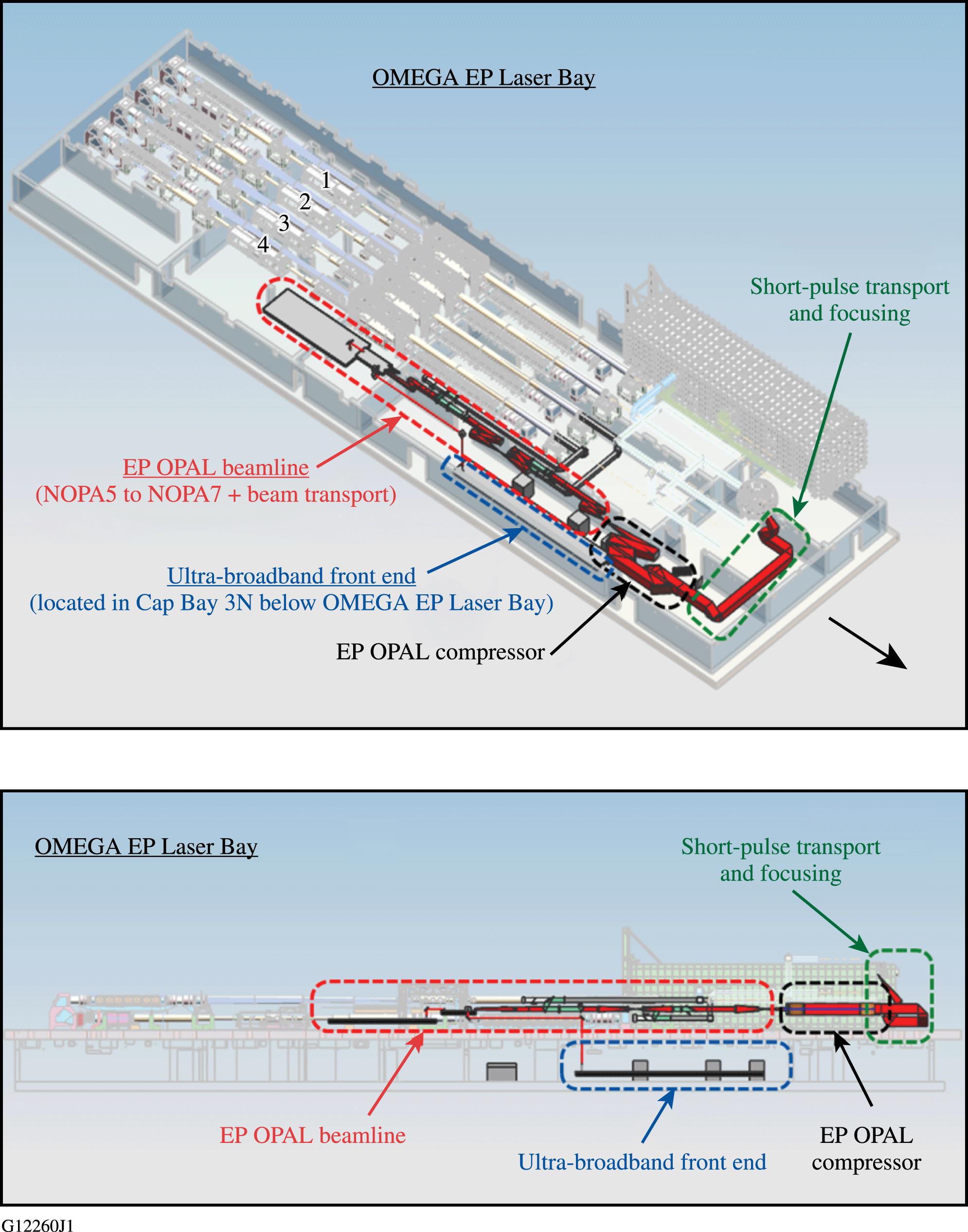
    Fig. 2. Isometric CAD views of the OMEGA EP Laser System, showing the locations of the main components of the EP OPAL system.
    The Multi-Terawatt (MTW) OPAL system in relation to the existing MTW laser. The MTW laser is reconfigured using three switchyards. Portions of the MTW laser that are not used for pumping the final amplifier stage of OPAL (NOPA5) are grayed out. OPA, optical parametric amplifier; UFE, ultrabroadband front end; DCP, diagnostic compressor package.
    Fig. 3. The Multi-Terawatt (MTW) OPAL system in relation to the existing MTW laser. The MTW laser is reconfigured using three switchyards. Portions of the MTW laser that are not used for pumping the final amplifier stage of OPAL (NOPA5) are grayed out. OPA, optical parametric amplifier; UFE, ultrabroadband front end; DCP, diagnostic compressor package.
    Schematic of the UFE subsystem. CPA, chirped-pulse amplification; SPM, self-phase modulation; AOPDF, acousto-optic programmable dispersive filter.
    Fig. 4. Schematic of the UFE subsystem. CPA, chirped-pulse amplification; SPM, self-phase modulation; AOPDF, acousto-optic programmable dispersive filter.
    The cylindrical Offner stretcher (COS) with the single-pass beam path shown. A second pass (not shown) is achieved using a periscope oriented at $45^{\circ }$ to retroreflect the beam with a 20-mm shift and $90^{\circ }$ beam rotation.
    Fig. 5. The cylindrical Offner stretcher (COS) with the single-pass beam path shown. A second pass (not shown) is achieved using a periscope oriented at $45^{\circ }$ to retroreflect the beam with a 20-mm shift and $90^{\circ }$ beam rotation.
    Stretcher output: (a) near-field, (b) far-field, and (c) spectrum. (d) Temporal contrast measured after NOPA1 and predicted for NOPA2 and NOPA3.
    Fig. 6. Stretcher output: (a) near-field, (b) far-field, and (c) spectrum. (d) Temporal contrast measured after NOPA1 and predicted for NOPA2 and NOPA3.
    Photo of the diagnostic compressor package (DCP), showing the two gratings, mount, and the roof mirror that is used for the two-pass configuration.
    Fig. 7. Photo of the diagnostic compressor package (DCP), showing the two gratings, mount, and the roof mirror that is used for the two-pass configuration.
    (a) SPIDER measurements of the spectral phase of the UFE pulses after compression in the DCP, before and after correction using the AOPDF. (b) Corresponding temporal pulse shapes calculated using the measured spectral phases and the super-Gaussian spectrum expected from NOPA4 after activation.
    Fig. 8. (a) SPIDER measurements of the spectral phase of the UFE pulses after compression in the DCP, before and after correction using the AOPDF. (b) Corresponding temporal pulse shapes calculated using the measured spectral phases and the super-Gaussian spectrum expected from NOPA4 after activation.
    The NOPA5 amplifier showing the two dichroic periscope mirror assemblies that are used to combine the pump and seed beams and separate any residual pump from the amplified signal.
    Fig. 9. The NOPA5 amplifier showing the two dichroic periscope mirror assemblies that are used to combine the pump and seed beams and separate any residual pump from the amplified signal.
    Schematic of the two-wavelength tuning-curve setup that is being used to determine the optimum noncollinear angle, $\unicode[STIX]{x1D6FC}_{\text{external}}$, for broadband gain.
    Fig. 10. Schematic of the two-wavelength tuning-curve setup that is being used to determine the optimum noncollinear angle, $\unicode[STIX]{x1D6FC}_{\text{external}}$, for broadband gain.
    Schematic of the grating compressor chamber showing the major subsystems and main beam path (dark blue), pre-shot, low-energy beam path for shot setup (orange), and the diagnostic beam paths used for on-shot diagnostics (light blue).
    Fig. 11. Schematic of the grating compressor chamber showing the major subsystems and main beam path (dark blue), pre-shot, low-energy beam path for shot setup (orange), and the diagnostic beam paths used for on-shot diagnostics (light blue).
    Schematic of the back end of the laser systems.
    Fig. 12. Schematic of the back end of the laser systems.
    J. Bromage, S.-W. Bahk, I. A. Begishev, C. Dorrer, M. J. Guardalben, B. N. Hoffman, J. B. Oliver, R. G. Roides, E. M. Schiesser, M. J. Shoup, M. Spilatro, B. Webb, D. Weiner, J. D. Zuegel. Technology development for ultraintense all-OPCPA systems[J]. High Power Laser Science and Engineering, 2019, 7(1): 010000e4
    Download Citation