
Yifei Li, Jie Hu, Wei Liu, Jiangang Yin, Jiangang Lu, "High period frequency LIPSS emerging on 304 stainless steel under the irradiation of femtosecond laser double-pulse trains," Chin. Opt. Lett. 19, 123801 (2021)
- Chinese Optics Letters
- Vol. 19, Issue 12, 123801 (2021)
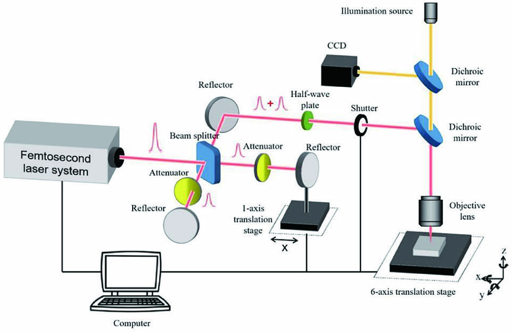
Fig. 1. Experimental setup with two beam arms.
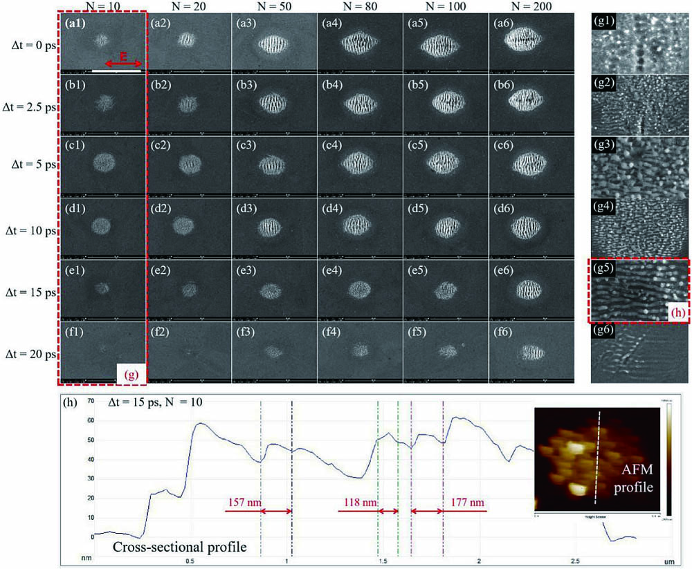
Fig. 2. Total fluence of double-pulse train: 0.388 J/cm2. Fluence of each subpulse: 0.194 J/cm2. (a)–(f) SEM images of LIPSS spots at different pulse delays Δt and pulse numbers N. (g) Magnifications of (a1)–(f1). (h) AFM-characterized cross-sectional profile of the structure in panel (g5); the orientation of the cross section is marked in the top-right corner. Laser polarization is indicated in (a1). Scale bar: (a)–(f), 10 µm; (g) is not to scale.
Fig. 3. Total laser fluence of double-pulse train was fixed at 0.388 J/cm2, and pulse delay Δt was maintained at 15 ps. Variation of LIPSS morphology in relation to pulse number under the following subpulse fluence combinations: (a) 0.194 + 0.194 J/cm2 (with 1:1 intrapulse energy ratio), (b) 0.233 + 0.155 J/cm2 (3:2), (c) 0.155 + 0.233 J/cm2 (2:3), (d) 0.310 + 0.078 J/cm2 (4:1), and (e) 0.078 + 0.310 J/cm2 (1:4). The only difference between (b) and (c) as well as (d) and (e) lies in their reversed subpulse arrival sequences. Morphology variation with the fluence combination is marked by the blue dotted rectangles. Morphology variation with subpulse arrival sequence is marked by the red dotted rectangle. Scale bars: 10 µm.
Fig. 4. Total fluence of double-pulse train: 0.544 J/cm2. Fluence of each subpulse: 0.272 J/cm2. (a)–(d) SEM images of LIPSS lines at different pulse delays Δt and scanning speeds vs. (e) Partially enlarged view of (d2). (f) Cross-sectional profile of the structure in panel (e) characterized by AFM, and the orientation of the cross section is marked in the top-right corner. Laser polarization is indicated in (a1). Scale bar: (a)–(d), 10 µm; (e), not to scale.
Fig. 5. Total laser fluence of the double-pulse train was fixed at 0.544 J/cm2, and the scanning speed vs was maintained at 100 µm/s. SEM images of LIPSS line under the following subpulse fluence combinations: (a) 0.272 + 0.272 J/cm2 (with 1:1 intrapulse energy ratio), (b) and (c) 0.233 + 0.311 J/cm2 (3:4) with reversed pulse arrival sequences relative to each other, and (d) and (e) 0.155 + 0.388 J/cm2 (2:5) with reversed pulse arrival sequences relative to each other. (f1), (f2) and (g1), (g2) are partial magnifications of the areas in (b3),(c3) and (b4),(c4). Scale bar: (a)–(e), 10 µm, marked in (a1); (f) and (g), not to scale.
Fig. 6. Total laser fluence was 0.544 J/cm2, and scanning speed vs was maintained at 100 µm/s. (a) LIPSS line width as a function of pulse delay under different intrapulse energy ratios, magnification at approximately Δt = 0 ps is presented. (b) LSFL period as a function of pulse delay under different subpulse fluence combinations. A negative pulse delay means that the subpulse arrival sequence is reversed. The LSFL period under the 0.544 J/cm2 single-pulse mode is also indicated in both (a) and (b) by a dotted line.


Set citation alerts for the article
Please enter your email address

© Copyright 2018-2021 | Chinese Laser Press. All Rights Reserved 沪ICP备15018463号-20