
Yifei Li, Jie Hu, Wei Liu, Jiangang Yin, Jiangang Lu, "High period frequency LIPSS emerging on 304 stainless steel under the irradiation of femtosecond laser double-pulse trains," Chin. Opt. Lett. 19, 123801 (2021)
- Chinese Optics Letters
- Vol. 19, Issue 12, 123801 (2021)
Abstract
1. Introduction
Laser-induced periodic surface structures (LIPSS)[
The function of an LIPSS-covered surface is dependent on the morphology of the LIPSS. In general, LIPSS are of two types depending on their morphology: low-spatial-frequency LIPSS (LSFL)[
In actual processing, LIPSS morphology can be directly regulated by laser parameter adjustment, such as laser wavelength[
Sign up for Chinese Optics Letters TOC. Get the latest issue of Chinese Optics Letters delivered right to you!Sign up now
In this work, we achieved control of LIPSS morphology on 304 stainless steel under double-pulse train irradiation. We applied subpulses of different fluences in an experiment to explore the effect of an unevenly distributed double-pulse train on LIPSS. Notably, when double-pulse irradiation was applied, a novel periodic structure comprising nanostripes and nanodroplets emerged; we are, to the best of our knowledge, the first to report on this intriguing phenomenon. We posit a qualitative explanation that this phenomenon is due to the weak energy coupling of subpulses at large intrapulse delays.
2. Experimental Setup
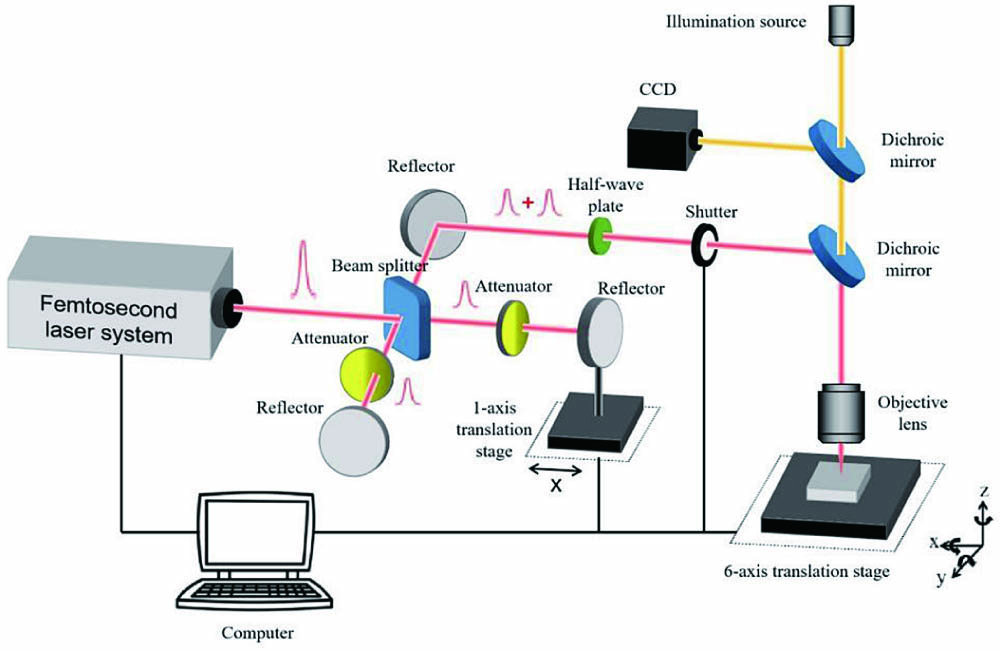
The experimental setup is illustrated in Fig. 1. In our experiments, a commercial chirped-pulse Ti:sapphire regenerative oscillator-amplifier laser system (Spitfire, Spectra-Physics Inc., USA), was used to generate a Gaussian-shaped femtosecond laser beam with a central wavelength of 800 nm, pulse duration of 35 fs, and maximum repetition rate of 1 kHz. Typically, a single-pulse train is adopted, but, when a double-pulse train is required, a beam splitter (in the form of a Michelson interferometer) is added to split the original laser beam emitted by the laser system into two beam arms, with the length of one arm being fixed and the length of the other arm being adjustable through a single-axis translation stage. Through such a setup, the interpulse time delay can be adjusted. To allow the fluences of the two arms to be tuned independently, an attenuator was placed in the path of each of the two arms. A half-wave plate was placed in the optical path to control the polarization orientation of the synthesized laser beam. The single-facet-polished 304 stainless steel samples (
![]()
Figure 1.Experimental setup with two beam arms.
Firstly, a series of LIPSS spots was obtained under different fluences and pulse numbers using a double-pulse train, and, in this study, the fluence was calculated using the following formula of peak laser fluence:
As mentioned, most studies have focused on manipulating LIPSS morphology using irradiation by either (but not both) single-pulse or double-pulse trains; in this work, we used double-pulse trains.
3. Experiments and Discussions
Figure 2 illustrates the evolution of an LIPSS spot with given pulse numbers under the irradiation of a
![]()
Figure 2.Total fluence of double-pulse train: 0.388 J/cm2. Fluence of each subpulse: 0.194 J/cm2. (a)–(f) SEM images of LIPSS spots at different pulse delays Δt and pulse numbers N. (g) Magnifications of (a1)–(f1). (h) AFM-characterized cross-sectional profile of the structure in panel (g5); the orientation of the cross section is marked in the top-right corner. Laser polarization is indicated in (a1). Scale bar: (a)–(f), 10 µm; (g) is not to scale.
We observed that the nanostripes began to appear when
Mitko et al.[
Subsequently, we attempted to control the LIPSS morphology by adopting different combinations of subpulse fluences and arrival sequences. As shown in Figs. 3(a3)–(a6), 3(c3)–3(c6), and 3(e3)–3(e6), the LIPSS morphology varied with the fluence combination. In Figs. 3(a3)–3(a5), only the aforementioned special periodic structure appeared, whereas LIPSS were formed in Figs. 3(c3)–3(c5) and in Figs. 3(e3)–3(e5). Although the LIPSS were formed in Fig. 3(a6), the size of the spot was relatively small. A previous study[
![]()
Figure 3.Total laser fluence of double-pulse train was fixed at 0.388 J/cm2, and pulse delay Δt was maintained at 15 ps. Variation of LIPSS morphology in relation to pulse number under the following subpulse fluence combinations: (a) 0.194 + 0.194 J/cm2 (with 1:1 intrapulse energy ratio), (b) 0.233 + 0.155 J/cm2 (3:2), (c) 0.155 + 0.233 J/cm2 (2:3), (d) 0.310 + 0.078 J/cm2 (4:1), and (e) 0.078 + 0.310 J/cm2 (1:4). The only difference between (b) and (c) as well as (d) and (e) lies in their reversed subpulse arrival sequences. Morphology variation with the fluence combination is marked by the blue dotted rectangles. Morphology variation with subpulse arrival sequence is marked by the red dotted rectangle. Scale bars: 10 µm.
Subsequently, we analyzed the morphology of the LIPSS line that was generated by a double-pulse train. Because the line could only be formed within a narrow scanning speed range at
![]()
Figure 4.Total fluence of double-pulse train: 0.544 J/cm2. Fluence of each subpulse: 0.272 J/cm2. (a)–(d) SEM images of LIPSS lines at different pulse delays Δt and scanning speeds vs. (e) Partially enlarged view of (d2). (f) Cross-sectional profile of the structure in panel (e) characterized by AFM, and the orientation of the cross section is marked in the top-right corner. Laser polarization is indicated in (a1). Scale bar: (a)–(d), 10 µm; (e), not to scale.
Different combinations of subpulse fluences (together with reversed subpulse arrival sequences) were also applied to the control of LIPSS morphology through the alteration of scanning parameters. Altering the fluence combination resulted in the following characteristics (Fig. 5). The morphology of the LIPSS line remained unchanged when the fluences of subpulses were equal [Fig. 5(a)] or very different [Figs. 5(d) and 5(e)] but changed when the fluences differed slightly [Figs. 5(b) and 5(c)]. Two notable phenomena were also observed. First, as illustrated in Figs. 5(b3) and 5(c3), HSFL and LSFL were formed when the subpulse with lower fluence arrived before and after the subpulse with the higher fluence, respectively. Second, when the pulse delay increased from 10 ps [Fig. 5(c3)] to 15 ps [Fig. 5(c4)], the special structure was formed instead of the LSFL, whereas the structure in Fig. 5(b4) remained similar to the one in Fig. 5(b3). The corresponding magnifications are shown in Figs. 5(f) and 5(g). These two phenomena can be explained by our two explanations posited in the preceding sections of this paper. Specifically, for the structures illustrated from Fig. 5(b3) to Fig. 5(c3), when the subpulse arrival sequence was reversed, the electron dynamics was altered, which eliminated the transition from LSFL to HSFL, leaving only LSFL. Furthermore, for the structures illustrated from Fig. 5(c3) to Fig. 5(c4), as
![]()
Figure 5.Total laser fluence of the double-pulse train was fixed at 0.544 J/cm2, and the scanning speed vs was maintained at 100 µm/s. SEM images of LIPSS line under the following subpulse fluence combinations: (a) 0.272 + 0.272 J/cm2 (with 1:1 intrapulse energy ratio), (b) and (c) 0.233 + 0.311 J/cm2 (3:4) with reversed pulse arrival sequences relative to each other, and (d) and (e) 0.155 + 0.388 J/cm2 (2:5) with reversed pulse arrival sequences relative to each other. (f1), (f2) and (g1), (g2) are partial magnifications of the areas in (b3),(c3) and (b4),(c4). Scale bar: (a)–(e), 10 µm, marked in (a1); (f) and (g), not to scale.
To quantitatively illustrate the morphological variation in Fig. 5, the LIPSS line width and the LSFL period as a function of the pulse delay are presented in Fig. 6. As shown in Fig. 6(a), the line width culminated at
![]()
Figure 6.Total laser fluence was 0.544 J/cm2, and scanning speed vs was maintained at 100 µm/s. (a) LIPSS line width as a function of pulse delay under different intrapulse energy ratios, magnification at approximately Δt = 0 ps is presented. (b) LSFL period as a function of pulse delay under different subpulse fluence combinations. A negative pulse delay means that the subpulse arrival sequence is reversed. The LSFL period under the 0.544 J/cm2 single-pulse mode is also indicated in both (a) and (b) by a dotted line.
4. Conclusion
In this study, femtosecond laser double-pulse trains were applied to generate LIPSS on the surface of 304 stainless steel, and a novel type of periodic structure was observed when the intrapulse delay was between 5 and 15 ps. The mechanism accounting for the formation of this kind of LIPSS was owed to the weak energy coupling of subpulses at large intrapulse delays. Moreover, various combinations of subpulse fluence were adopted so as to observe their influence on the morphology of LIPSS formation. The experimental results of this study indicated that under double-pulse trains, LIPSS formation could be controlled by intrapulse delay, subpulse fluence combination, together with subpulse arrival sequences.
References
[1] M. Birnbaum. Semiconductor surface damage produced by ruby lasers. J. Appl. Phys., 36, 3688(1965).
[2] Z. Fang, J. Shao. Femtosecond laser-induced periodic surface structure on fused silica surface. Optik, 127, 1171(2016).
[3] S. Höhm, A. Rosenfeld, J. Krüger, J. Bonse. Femtosecond laser-induced periodic surface structures on silica. J. Appl. Phys., 112, 014901(2012).
[4] T. Jiang, S. Gao, Z. Tian, H. Zhang, L. Niu. Fabrication of diamond ultra-fine structures by femtosecond laser. Chin. Opt. Lett., 18, 101402(2020).
[5] W. Han, L. Jiang, X. Li, P. Liu, L. Xu, Y. Lu. Continuous modulations of femtosecond laser-induced periodic surface structures and scanned line-widths on silicon by polarization changes. Opt. Express, 21, 15505(2013).
[6] J. Bonse, J. Krüger. Pulse number dependence of laser-induced periodic surface structures for femtosecond laser irradiation of silicon. J. Appl. Phys., 108, 034903(2010).
[7] M. Martínez-Calderon, A. Rodríguez, A. Dias-Ponte, M. Morant-Miñana, M. Gómez-Aranzadi, S. Olaizola. Femtosecond laser fabrication of highly hydrophobic stainless steel surface with hierarchical structures fabricated by combining ordered microstructures and LIPSS. Appl. Surf. Sci., 374, 81(2016).
[8] J. Bonse, R. Koter, M. Hartelt, D. Spaltmann, S. Pentzien, S. Höhm, A. Rosenfeld, J. Krüger. Femtosecond laser-induced periodic surface structures on steel and titanium alloy for tribological applications. Appl. Phys. A, 117, 103(2014).
[9] B. Wu, C. Wang, Z. Luo, J. Li, S. Man, K. Ding, J. A. Duan. Controllable annulus micro-/nanostructures on copper fabricated by femtosecond laser with spatial doughnut distribution. Chin. Opt. Lett., 18, 013101(2020).
[10] T. Yang, H. Lin, B. Jia. Ultrafast direct laser writing of 2D materials for multifunctional photonics devices. Chin. Opt. Lett., 18, 023601(2020).
[11] J. Bonse, S. Höhm, S. V. Kirner, A. Rosenfeld, J. Krüger. Laser-induced periodic surface structures—a scientific evergreen. IEEE J. Sel. Top. Quantum Electron., 23, 9000615(2016).
[12] A. Y. Vorobyev, C. Guo. Colorizing metals with femtosecond laser pulses. Appl. Phys. Lett., 92, 041914(2008).
[13] B. Dusser, Z. Sagan, H. Soder, N. Faure, J.-P. Colombier, M. Jourlin, E. Audouard. Controlled nanostructrures formation by ultra fast laser pulses for color marking. Opt. Express, 18, 2913(2010).
[14] A.-M. Kietzig, M. Negar Mirvakili, S. Kamal, P. Englezos, S. G. Hatzikiriakos. Laser-patterned super-hydrophobic pure metallic substrates: Cassie to Wenzel wetting transitions. J. Adhesion Sci. Technol., 25, 2789(2011).
[15] E. Rebollar, M. Castillejo, T. A. Ezquerra. Laser induced periodic surface structures on polymer films: from fundamentals to applications. Euro. Polym. J., 73, 162(2015).
[16] A. Cunha, A.-M. Elie, L. Plawinski, A. P. Serro, A. M. B. do Rego, A. Almeida, M. C. Urdaci, M.-C. Durrieu, R. Vilar. Femtosecond laser surface texturing of titanium as a method to reduce the adhesion of Staphylococcus aureus and biofilm formation. Appl. Surf. Sci., 360, 485(2016).
[17] J. Sipe, J. F. Young, J. Preston, H. Van Driel. Laser-induced periodic surface structure. I. Theory. Phys. Rev. B, 27, 1141(1983).
[18] J. Bonse, A. Rosenfeld, J. Krüger. On the role of surface plasmon polaritons in the formation of laser-induced periodic surface structures upon irradiation of silicon by femtosecond-laser pulses. J. Appl. Phys., 106, 104910(2009).
[19] M. Huang, F. Zhao, Y. Cheng, N. Xu, Z. Xu. Origin of laser-induced near-subwavelength ripples: interference between surface plasmons and incident laser. ACS Nano, 3, 4062(2009).
[20] A. Borowiec, H. Haugen. Subwavelength ripple formation on the surfaces of compound semiconductors irradiated with femtosecond laser pulses. Appl. Phys. Lett., 82, 4462(2003).
[21] F. Costache, M. Henyk, J. Reif. Modification of dielectric surfaces with ultra-short laser pulses. Appl. Surf. Sci., 186, 352(2002).
[22] Y. Dong, P. Molian. Coulomb explosion-induced formation of highly oriented nanoparticles on thin films of 3C–SiC by the femtosecond pulsed laser. Appl. Phys. Lett., 84, 10(2004).
[23] T. Crawford, H. Haugen. Sub-wavelength surface structures on silicon irradiated by femtosecond laser pulses at 1300 and 2100 nm wavelengths. Appl. Surf. Sci., 253, 4970(2007).
[24] G. Li, J. Li, Y. Hu, C. Zhang, X. Li, J. Chu, W. Huang. Femtosecond laser color marking stainless steel surface with different wavelengths. Appl. Phys. A, 118, 1189(2015).
[25] E. Hsu, T. Crawford, H. Tiedje, H. Haugen. Periodic surface structures on gallium phosphide after irradiation with 150 fs–7 ns laser pulses at 800 nm. Appl. Phys. Lett., 91, 111102(2007).
[26] J. Bonse, S. Höhm, A. Rosenfeld, J. Krüger. Sub-100-nm laser-induced periodic surface structures upon irradiation of titanium by Ti:sapphire femtosecond laser pulses in air. Appl. Phys. A, 110, 547(2013).
[27] P. Gregorčič, M. Sedlaček, B. Podgornik, J. Reif. Formation of laser-induced periodic surface structures (LIPSS) on tool steel by multiple picosecond laser pulses of different polarizations. Appl. Surf. Sci., 387, 698(2016).
[28] A. Vorobyev, V. Makin, C. Guo. Periodic ordering of random surface nanostructures induced by femtosecond laser pulses on metals. J. Appl. Phys., 101, 034903(2007).
[29] S. Höhm, A. Rosenfeld, J. Krüger, J. Bonse. Laser-induced periodic surface structures on titanium upon single- and two-color femtosecond double-pulse irradiation. Opt. Express, 23, 25959(2015).
[30] M. Barberoglou, D. Gray, E. Magoulakis, C. Fotakis, P. Loukakos, E. Stratakis. Controlling ripples’ periodicity using temporally delayed femtosecond laser double pulses. Opt. Express, 21, 18501(2013).
[31] A. Rosenfeld, M. Rohloff, S. Höhm, J. Krüger, J. Bonse. Formation of laser-induced periodic surface structures on fused silica upon multiple parallel polarized double-femtosecond-laser-pulse irradiation sequences. Appl. Surf. Sci., 258, 9233(2012).
[32] W. Han, L. Jiang, X. Li, Q. Wang, H. Li, Y. Lu. Anisotropy modulations of femtosecond laser pulse induced periodic surface structures on silicon by adjusting double pulse delay. Opt. Express, 22, 15820(2014).
[33] J. Yao, C. Zhang, H. Liu, Q. Dai, L. Wu, S. Lan, A. V. Gopal, V. A. Trofimov, T. M. Lysak. Selective appearance of several laser-induced periodic surface structure patterns on a metal surface using structural colors produced by femtosecond laser pulses. Appl. Surf. Sci., 258, 7625(2012).
[34] F. Fraggelakis, G. Mincuzzi, J. Lopez, I. Manek-Hönninger, R. Kling. Controlling 2D laser nano structuring over large area with double femtosecond pulses. Appl. Surf. Sci., 470, 677(2019).
[35] F. Fraggelakis, G. Giannuzzi, C. Gaudiuso, I. Manek-Hönninger, G. Mincuzzi, A. Ancona, R. Kling. Double- and multi-femtosecond pulses produced by birefringent crystals for the generation of 2D laser-induced structures on a stainless steel surface. Materials, 12, 1257(2019).
[36] J. Liu. Simple technique for measurements of pulsed Gaussian-beam spot sizes. Opt. Lett., 7, 196(1982).
[37] D. W. Müller, T. Fox, P. G. Grützmacher, S. Suarez, F. Mücklich. Applying ultrashort pulsed direct laser interference patterning for functional surfaces. Sci. Rep., 10, 3647(2020).
[38] V. Mitko, G. Römer, A. Huis, J. Skolski, J. Obona, V. Ocelík, J. De Hosson. Properties of high-frequency sub-wavelength ripples on stainless steel 304L under ultra short pulse laser irradiation. Phys. Procedia, 12, 99(2011).
[39] F. Fraggelakis, E. Stratakis, P. Loukakos. Control of periodic surface structures on silicon by combined temporal and polarization shaping of femtosecond laser pulses. Appl. Surf. Sci., 444, 154(2018).


Set citation alerts for the article
Please enter your email address

© Copyright 2018-2021 | Chinese Laser Press. All Rights Reserved 沪ICP备15018463号-20