• High Power Laser Science and Engineering
  • Vol. 9, Issue 4, 04000e61 (2021)
P. Cinquegrana, A. Demidovich, G. Kurdi, I. Nikolov, P. Sigalotti, P. Susnjar, and M. B. Danailov*
Author Affiliations
  • Elettra-Sincrotrone Trieste, 34149Trieste, Italy
  • show less
    DOI: 10.1017/hpl.2021.49 Cite this Article Set citation alerts
    P. Cinquegrana, A. Demidovich, G. Kurdi, I. Nikolov, P. Sigalotti, P. Susnjar, M. B. Danailov. The seed laser system of the FERMI free-electron laser: design, performance and near future upgrades[J]. High Power Laser Science and Engineering, 2021, 9(4): 04000e61 Copy Citation Text show less
    HGHG seeding scheme at FERMI: (a) single stage, FEL1; (b) fresh-bunch double stage, FEL2. DS: dispersive section.
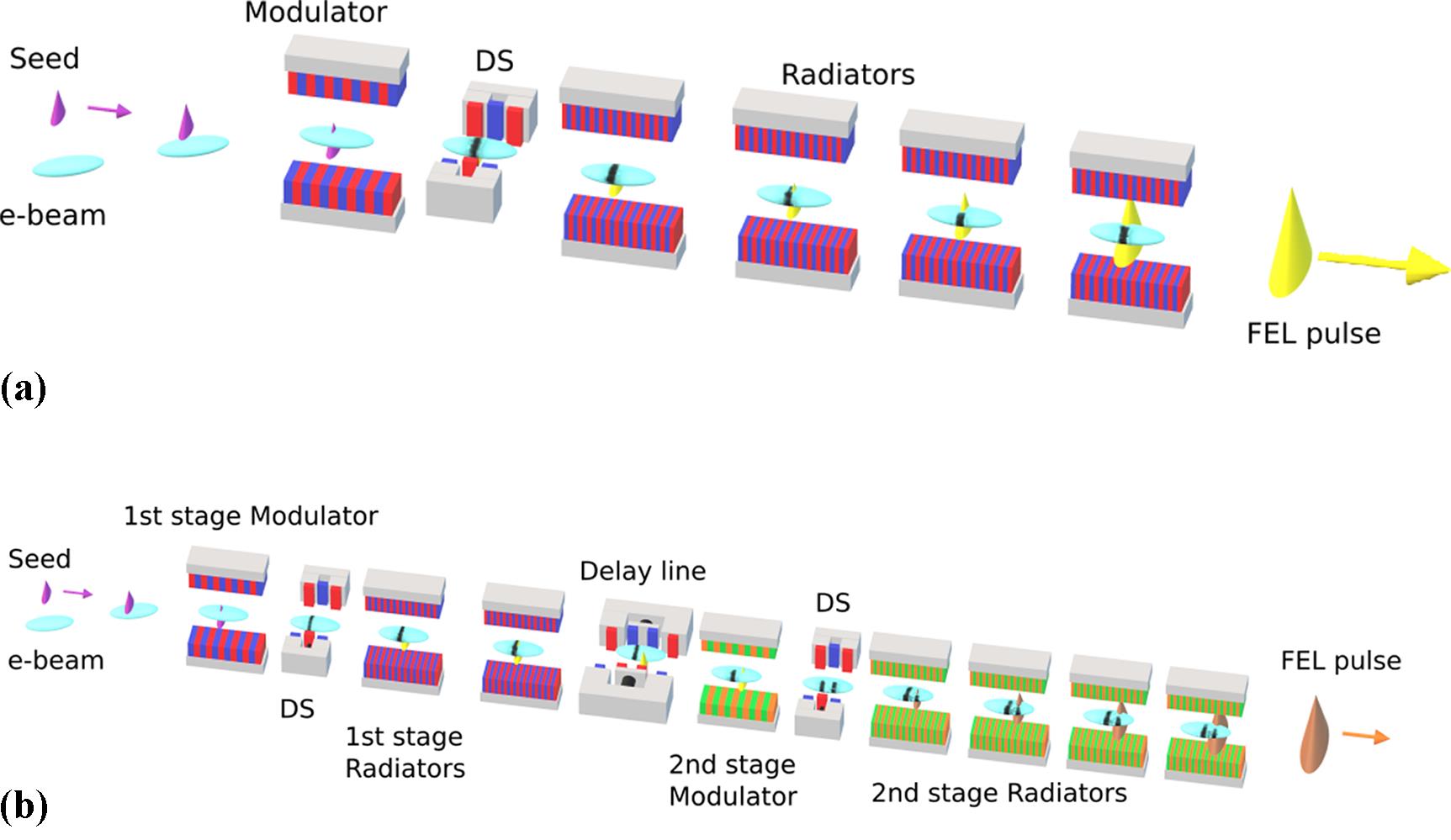
    Fig. 1. HGHG seeding scheme at FERMI: (a) single stage, FEL1; (b) fresh-bunch double stage, FEL2. DS: dispersive section.
    Schematic layout of the seed laser table. THG, third harmonic generation setup; SLU, pulse sent to the user stations; IR-SSXC, IR single-shot cross-correlator; UV-AC, UV autocorrelator; UV-XCORR, UV cross-correlator; COMPR, UV grating compressor.
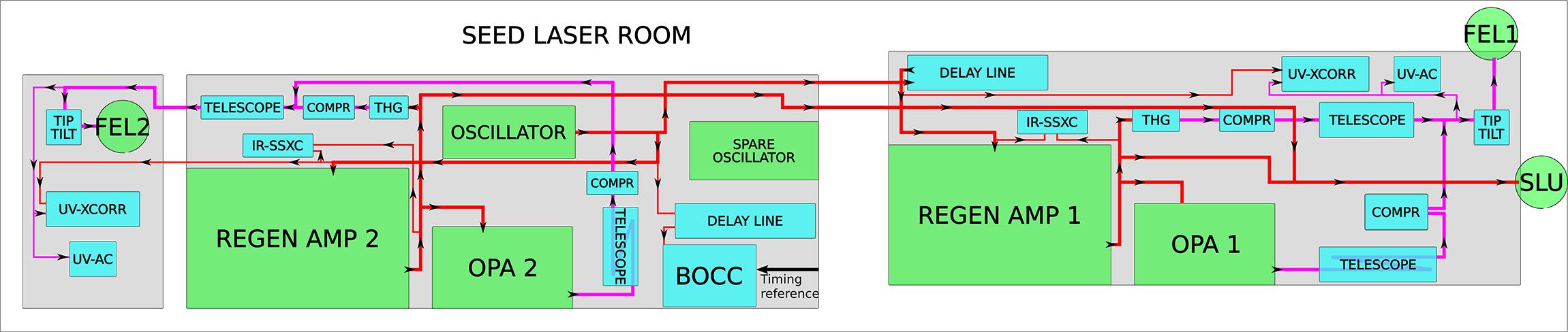
    Fig. 2. Schematic layout of the seed laser table. THG, third harmonic generation setup; SLU, pulse sent to the user stations; IR-SSXC, IR single-shot cross-correlator; UV-AC, UV autocorrelator; UV-XCORR, UV cross-correlator; COMPR, UV grating compressor.
    OPA1 output pulse energy versus wavelength for (a) second harmonic of the sum frequency of signal (SH-SFS) process and (b) fourth harmonic of signal (FHS) process.
    Fig. 3. OPA1 output pulse energy versus wavelength for (a) second harmonic of the sum frequency of signal (SH-SFS) process and (b) fourth harmonic of signal (FHS) process.
    FEL1 wavelength tunability and estimated pulse duration (from Equation (2)) at harmonic orders 3–15 for (a) seed range 232–267 nm and (b) seed range 295–360 nm.
    Fig. 4. FEL1 wavelength tunability and estimated pulse duration (from Equation (2)) at harmonic orders 3–15 for (a) seed range 232–267 nm and (b) seed range 295–360 nm.
    FROG trace of the compressed seed pulse at 325 nm: (a) measured and (b) retrieved FROG trace with a G error of G = 0.0077; (c) retrieved temporal intensity and phase; (d) retrieved spectral intensity (red) and phase with the independently measured spectrum (blue). The retrieved temporal and spectral intensity FWHM values are 49 fs and 2.73 nm, respectively.
    Fig. 5. FROG trace of the compressed seed pulse at 325 nm: (a) measured and (b) retrieved FROG trace with a G error of G = 0.0077; (c) retrieved temporal intensity and phase; (d) retrieved spectral intensity (red) and phase with the independently measured spectrum (blue). The retrieved temporal and spectral intensity FWHM values are 49 fs and 2.73 nm, respectively.
    FEL2 pulse duration with OPA and THG seed, with first stage harmonic orders 3–15 and second stage harmonic orders 2–7.
    Fig. 6. FEL2 pulse duration with OPA and THG seed, with first stage harmonic orders 3–15 and second stage harmonic orders 2–7.
    OPA1 output central wavelength stability measured over 4 hours.
    Fig. 7. OPA1 output central wavelength stability measured over 4 hours.
    Schematic layout of the seed beam insertion breadboard (IBB) of FEL1. SLR, beam from seed laser room; CCD BT, CCD VU1, CCD VU2, cameras for monitoring the beam after the optical transport and in two virtual planes corresponding to the undulator entrance and exit, respectively; EM, energy meter.
    Fig. 8. Schematic layout of the seed beam insertion breadboard (IBB) of FEL1. SLR, beam from seed laser room; CCD BT, CCD VU1, CCD VU2, cameras for monitoring the beam after the optical transport and in two virtual planes corresponding to the undulator entrance and exit, respectively; EM, energy meter.
    Pointing stability of the FEL1 seed beam position in the horizontal (upper trace) and vertical (lower trace) planes, measured on CCD VU2 over 8 hours of continuous operation at 50 Hz with transverse feedback ON; one shot is registered every second.
    Fig. 9. Pointing stability of the FEL1 seed beam position in the horizontal (upper trace) and vertical (lower trace) planes, measured on CCD VU2 over 8 hours of continuous operation at 50 Hz with transverse feedback ON; one shot is registered every second.
    Schematic layout of the seed laser synchronization setup. TMU Rf, coarse synchronization unit; LNA, low-noise amplifiers; PI, proportional integral; TMU, timing control unit; Ti:Sa, titanium sapphire; pzt, piezo-based actuator.
    Fig. 10. Schematic layout of the seed laser synchronization setup. TMU Rf, coarse synchronization unit; LNA, low-noise amplifiers; PI, proportional integral; TMU, timing control unit; Ti:Sa, titanium sapphire; pzt, piezo-based actuator.
    (a) Phase noise and timing jitter of the seed oscillator. Left axis, integrated timing jitter; right axis, phase noise spectral density. (b) Timing stability of the seed laser oscillator, measured out of loop using a second balanced optical cross correlator (BOCC).
    Fig. 11. (a) Phase noise and timing jitter of the seed oscillator. Left axis, integrated timing jitter; right axis, phase noise spectral density. (b) Timing stability of the seed laser oscillator, measured out of loop using a second balanced optical cross correlator (BOCC).
    Schematic layout of the seed laser for users (SLU) system. SLR, beam from the seed laser room; Low Vacuum BT, optical beam transport in chambers and tubes at 1–10 mbar vacuum level; CDP, common distribution point of the SLU pulse in the FERMI Experimental Hall; CCD BT, camera for beam position control; COMPR, grating compressor.
    Fig. 12. Schematic layout of the seed laser for users (SLU) system. SLR, beam from the seed laser room; Low Vacuum BT, optical beam transport in chambers and tubes at 1–10 mbar vacuum level; CDP, common distribution point of the SLU pulse in the FERMI Experimental Hall; CCD BT, camera for beam position control; COMPR, grating compressor.
    Expected tunability of FEL1 in echo enabled harmonic generation (EEHG) mode by using harmonic order n = −1 and harmonic order m = 13–26.
    Fig. 13. Expected tunability of FEL1 in echo enabled harmonic generation (EEHG) mode by using harmonic order n = −1 and harmonic order m = 13–26.
    Planned seed laser system layout after the upgrade. RG1, RG2, RG3, regenerative amplifiers; IBB1 FEL1 and IBB2 FEL2 are the insertion breadboards of the corresponding seed pulse to the FEL lines; SH, second harmonic; EOS FEL2, beam provided for electro-optical sampling setup; the solid blocks and arrows indicate existing units and beam transport lines while the dashed blocks and lines indicate planned additions.
    Fig. 14. Planned seed laser system layout after the upgrade. RG1, RG2, RG3, regenerative amplifiers; IBB1 FEL1 and IBB2 FEL2 are the insertion breadboards of the corresponding seed pulse to the FEL lines; SH, second harmonic; EOS FEL2, beam provided for electro-optical sampling setup; the solid blocks and arrows indicate existing units and beam transport lines while the dashed blocks and lines indicate planned additions.
    ParameterValue
    Central wavelength range (nm)230–360
    Continuous wavelength tunability (nm)35–40
    Relative central wavelength stability (δλc/λc)<10–4
    Pulse peak power (MW)≥100 (≥150 in FEL2 mode)
    Pulse duration (fs)60–120
    Timing jitter with respect to pulsed reference (fs, RMS)30
    Energy stability (RMS)<2%
    Beam dimension in the modulator 1/e2 radius (mm)0.4–0.6
    Beam pointing stability (μm, RMS)<40
    Repetition rate (Hz)50, 10
    Table 1. Main parameters requested for the FERMI seed pulses.
    ParameterValue
    Fundamental wavelength (nm)795 (–10 or + 5)
    Pulse energy (mJ)3
    Pulse duration (fs, FWHM)55–65
    Max peak power (W/cm2)~5 × 1014
    Shot-to-shot timing jitter with respect to FEL pulse (fs, RMS)<7
    Energy stability fundamental (%, RMS)0.5
    Pointing stability on sample (μm, RMS)3–5
    Harmonic generation option wavelengths (nm)397 ± 3, 265 ± 2, 200 ± 2
    Options under development:
    OPA with UV to mid-IR stages (nm)240–15,000
    Pulse length fundamental with hollow fibre pulse compressor (fs)<20
    Table 2. Main parameters of the seed laser for users (SLU) pulses at the FERMI end-stations.
    ParameterValue
    Central wavelength range Seed 1 (nm)264 ± 2
    Central wavelength range Seed 2 (nm)245–266
    Relative wavelength stability Seed 2<10–4
    Pulse peak power Seed 1 (MW)≥100
    Pulse peak power Seed 2 (MW)≥150
    Pulse duration Seed 1 (fs)150–1000
    Pulse duration Seed 2 (fs)60–120
    Time-bandwidth product Seed 2 (TL)<1.1
    Shot-to-shot timing jitter Seed 1–Seed 2 (fs, RMS)≤15
    Beam dimension Seed 1 in the modulator 1/e2 radius (mm)0.6
    Beam dimension Seed 2 in the modulator 1/e2 radius (mm)<0.4
    Table 3. Main parameters requested for Seeds 1 and 2 in EEHG mode.
    P. Cinquegrana, A. Demidovich, G. Kurdi, I. Nikolov, P. Sigalotti, P. Susnjar, M. B. Danailov. The seed laser system of the FERMI free-electron laser: design, performance and near future upgrades[J]. High Power Laser Science and Engineering, 2021, 9(4): 04000e61
    Download Citation