• Acta Optica Sinica
  • Vol. 38, Issue 7, 0711003 (2018)
Chunyue Zhang1、2, Shuyan Xu1、*, Boqian Xu1, Xin Qi1、2, and Guohao Ju1
Author Affiliations
  • 1 Changchun Institute of Optics, Fine Mechanics and Physics, Chinese Academy of Sciences, Changchun, Jilin 130033, China
  • 2 University of Chinese Academy of Sciences, Beijing 100049, China
  • show less
    DOI: 10.3788/AOS201838.0711003 Cite this Article Set citation alerts
    Chunyue Zhang, Shuyan Xu, Boqian Xu, Xin Qi, Guohao Ju. Correction for Effect of Calibration Error on Accuracy of Co-Phasing Error Detection of Dispersed Fringe[J]. Acta Optica Sinica, 2018, 38(7): 0711003 Copy Citation Text show less
    Production principle of dispersed fringe image
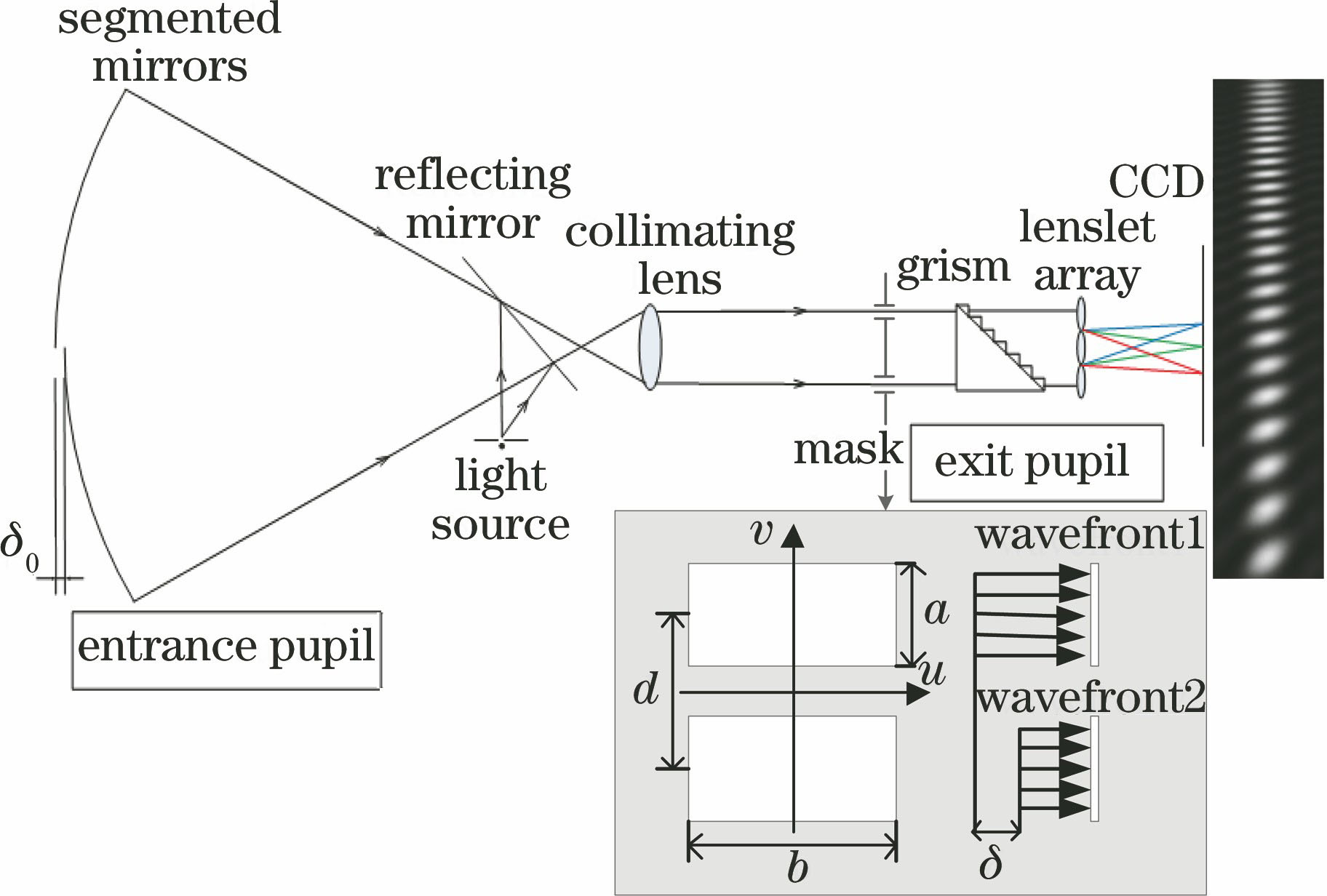
    Fig. 1. Production principle of dispersed fringe image
    Two-dimensional information extraction of dispersed fringe image by the MPP method
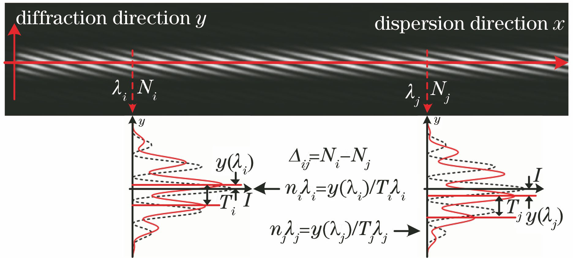
    Fig. 2. Two-dimensional information extraction of dispersed fringe image by the MPP method
    Schematic of the calibration error for the central line position of dispersed fringe image
    Fig. 3. Schematic of the calibration error for the central line position of dispersed fringe image
    Effect of piston phase error on the diffraction pattern of double rectangle hole. (a) Double beam interference factor without piston phase error; (b) double beam interference factor with piston phase error; (c) single rectangle hole diffraction factor without piston phase error; (d) single rectangle hole diffraction factor with piston phase error; (e) one-dimensional diffraction pattern of double rectangle hole without piston phase error; (f) one-dimensional diffraction pattern of double rectang
    Fig. 4. Effect of piston phase error on the diffraction pattern of double rectangle hole. (a) Double beam interference factor without piston phase error; (b) double beam interference factor with piston phase error; (c) single rectangle hole diffraction factor without piston phase error; (d) single rectangle hole diffraction factor with piston phase error; (e) one-dimensional diffraction pattern of double rectangle hole without piston phase error; (f) one-dimensional diffraction pattern of double rectang
    Difference between the wavelength and the peak offset corresponding to the same peak position when the center line of the fringe is different
    Fig. 5. Difference between the wavelength and the peak offset corresponding to the same peak position when the center line of the fringe is different
    Detection error before and after the improvement of the MPP method as the rotation angle calibration error increases
    Fig. 6. Detection error before and after the improvement of the MPP method as the rotation angle calibration error increases
    Experimental optical path for the detection of piston error
    Fig. 7. Experimental optical path for the detection of piston error
    Dispersed fringe images corresponding to the two sets of piston error in the target wavelength range. (a) 0.055; (b) 100.055
    Fig. 8. Dispersed fringe images corresponding to the two sets of piston error in the target wavelength range. (a) 0.055; (b) 100.055
    Rotated angle ε /(°)Detected piston error /μmDetected error /μmRotated angle ε /(°)Detected piston error /μmDetected error /μm
    0-19.9960.0040-19.9960.004
    0.2-19.6120.388-0.2-20.514-0.514
    0.4-18.9751.025-0.4-21.019-1.019
    0.6-18.4531.547-0.6-21.539-1.539
    0.8-17.9372.063-0.8-22.052-2.052
    1-17.4332.567-1-22.556-2.556
    Table 1. Detection results of the MPP method with different rotated angles when the piston error is -20 μm
    Piston errorDetection error before correctionDetection error after correction
    0.0550.1670.027
    100.0553.6200.423
    Table 2. Accuracy of the MPP method before and after correctionμm
    Chunyue Zhang, Shuyan Xu, Boqian Xu, Xin Qi, Guohao Ju. Correction for Effect of Calibration Error on Accuracy of Co-Phasing Error Detection of Dispersed Fringe[J]. Acta Optica Sinica, 2018, 38(7): 0711003
    Download Citation