
Hua-bao CAO, Hu-shan WANG, Hao YUAN, Xin LIU, Pei HUANG, Yi-shan WANG, Wei ZHAO, Yu-xi FU. Research Progress of Mid-infrared Femtosecond Sources Based on Optical Parametric Amplification (Invited)[J]. Acta Photonica Sinica, 2020, 49(11): 59
- Acta Photonica Sinica
- Vol. 49, Issue 11, 59 (2020)
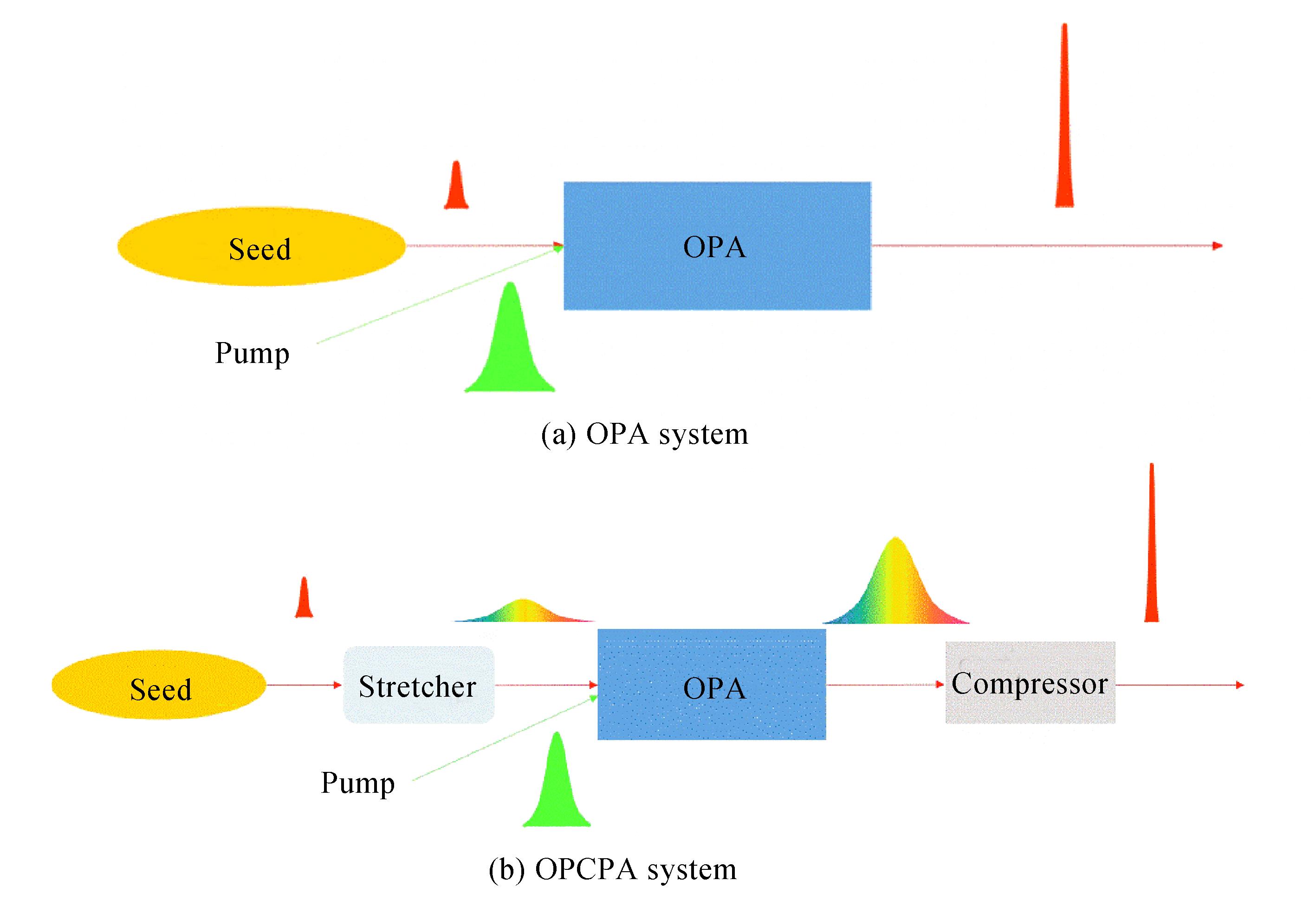
Fig. 1. The principle of OPA, OPCPA and DC-OPA
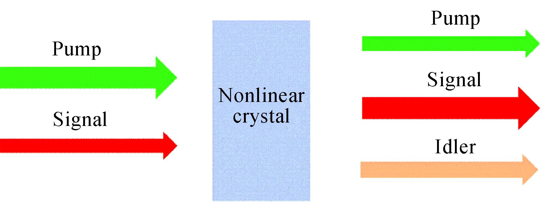
Fig. 2. Schematic of an optical parametric amplifier
Fig. 3. Collinear and non-collinear phase-matching geometries
Fig. 4. Calculated gain spectrum of a 3 mm BBO under the type-I phase-matching condition, and the calculated gain spectrum at the pump wavelength of 708 nm with different phase-matching angle[19]
Fig. 5. A typical seed generation scheme
Fig. 6. Spectral range of the supercontinuum generated in various material while driven by light of different wavelengths[25]
Fig. 7. Reflectance and GDD of the complementary chirped mirror pair in the wavelength of 2~4 μm[26]
Fig. 8. Measured reflectance, transmittance, absorption and GDD curves of the chirped mirror[27]. Reprinted with permission from Ref.[27] ©The Optical Society
Fig. 9. Transmittances and GVD of several typical materials for dispersion management
Fig. 10. Transmittance of the liquid-crystal in the SLM and the setup of the SLM based pulse shaper[30]
Fig. 11. Some typical reports on the performance of mid-infrared femtosecond sources based on optical parametrical amplification technique driven by pumps of different wavelength in recent years
Fig. 12. Schematic of DC-OPA with peak power of 0.3 TW[40]
Fig. 13. Schematic of the mid-infrared source with average power of 15.1 W[46]
Fig. 14. 9 μm femtosecond mid-infrared source based on LiGaS2[52]. Reprinted with permission from Ref.[52] ©The Optical Society
Fig. 15. 7 μm femtosecond mid-infrared source with pulse energy of millijoule level[59]. Reprinted with permission from Ref.[59] ©The Optical Society
Fig. 16. Proof-of-principle schematic setup of the 4~12 μm mid-Infrared source[60]
Fig. 17. Layout of the Ho:YAG thin-disk laser
Fig. 18. Thermal imaging of BBO crystal pumped with optical power of 120 W at 515 nm and the photograph of the BBO-sapphire sandwich structure [63-64]
Fig. 19. Schematic of the wavelength tunable optical vortex OPA system[65]. Reprinted with permission from Ref.[65] ©The Optical Society
Fig. 20. Schematic of the 4 μm optical vortex OPCPA system[66]
Fig. 21. Spectra of the optical vortex beam measured at four different quadrants[66]
Fig. 22. Schematic of the experimental setup for second harmonic generation of radially polarized beam with two nonlinear crystals[67]. Reprinted with permission from Ref.[67] ©The Optical Society
|
Table 1. Parameters of the frequently employed nonlinear crystals in mid-infrared range
|
Table 2. Parameters of frequently used materials for supercontinuum generation[25]


Set citation alerts for the article
Please enter your email address

© Copyright 2018-2021 | Chinese Laser Press. All Rights Reserved 沪ICP备15018463号-20