
Xinran Yuan, Jingyang Deng, Dihua Xu, Xiangchao Sun, Yanhao Yu, Qidai Chen. Fabrication of Microlens Arrays with High Numerical Aperture Based on Femtosecond Laser Self-Modulating Processing Method[J]. Acta Optica Sinica, 2023, 43(16): 1623019
- Acta Optica Sinica
- Vol. 43, Issue 16, 1623019 (2023)
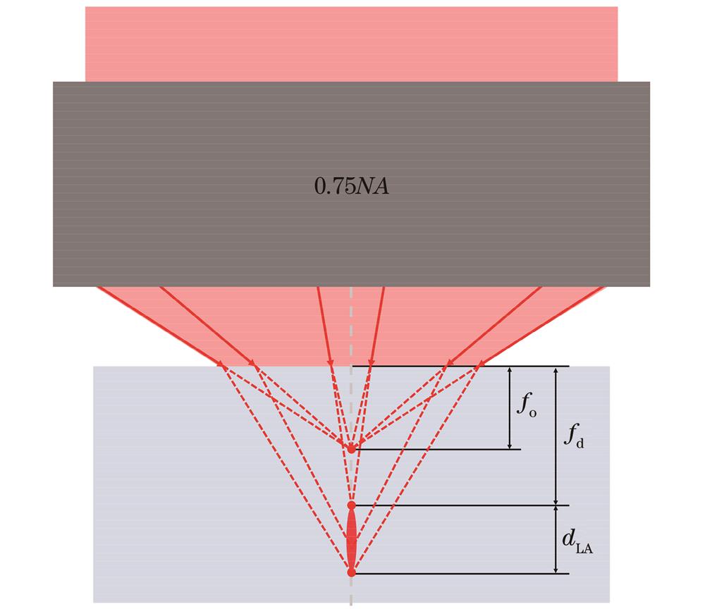
Fig. 1. Change of spot geometry caused by spherical aberration when laser focusing across a plane interface from air into the sample

Fig. 2. Lightpath of self-modulating femtosecond laser processing system
Fig. 3. Comparison of the process of forming microlens by wet etching. (a) Comparison of etching process between front-side processing method and self-modulating processing method; (b) confocal 3D images of the structure with regular front-side processing method when etching 0 min, 20 min, and 70 min; (c) confocal 3D images of the structure with self-modulating method when etching 0 min, 20 min, and 70 min
Fig. 4. Morphology parameters of microlenses processed by self-modulating method with different pulse energies. (a) Confocal microscope pictures of microlenses at different pulse energies; (b) cross-section profiles of microlenses prepared at different pulse energies; (c) numerical aperture and radius of curvature of the microlens vary with the pulse energy
Fig. 5. Comparison of microlens morphology parameters prepared by self-modulating processing method and regular front-side processing method when changing the defocus position. (a) Morphologies of microlenses at different defocus positions using self-modulating processing method,(i) shows the optical microscope images of microlenses with defocus positions from 1 μm to 7 μm, and (ii) shows the confocal sectional profile of microlenses with defocus position from 8 μm to 14 μm; (b) diameter and depth changed with defocus position during self-modulating processing; (c)
Fig. 6. Morphological characterization and imaging results of large-area microlens arrays. (a) Optical microscope images; (b) scanning electron microscopy images; (c) imaging results tested by optical microscopy; (d) focusing results tested by optical microscopy
Fig. 7. Morphological characterization and imaging results of microlenses with different
|
Table 1.

Set citation alerts for the article
Please enter your email address
© Copyright 2018-2021 | Chinese Laser Press. All Rights Reserved 沪ICP备15018463号-20