
Jong Hyun Lim, Jin Wook Kim, Geum Jae Yoon, Ayse Turak, Woo Young Kim. Effect of various red phosphorescent dopants in single emissive white phosphorescent organic light-emitting devices[J]. Chinese Optics Letters, 2017, 15(5): 051602
- Chinese Optics Letters
- Vol. 15, Issue 5, 051602 (2017)
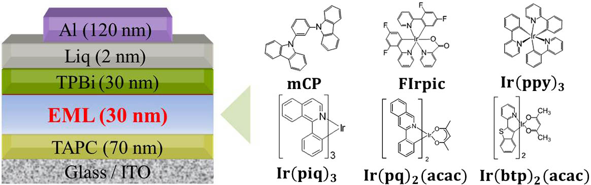
Fig. 1. Schematic structure of white PHOLEDs and configuration molecules of organic materials in EML.
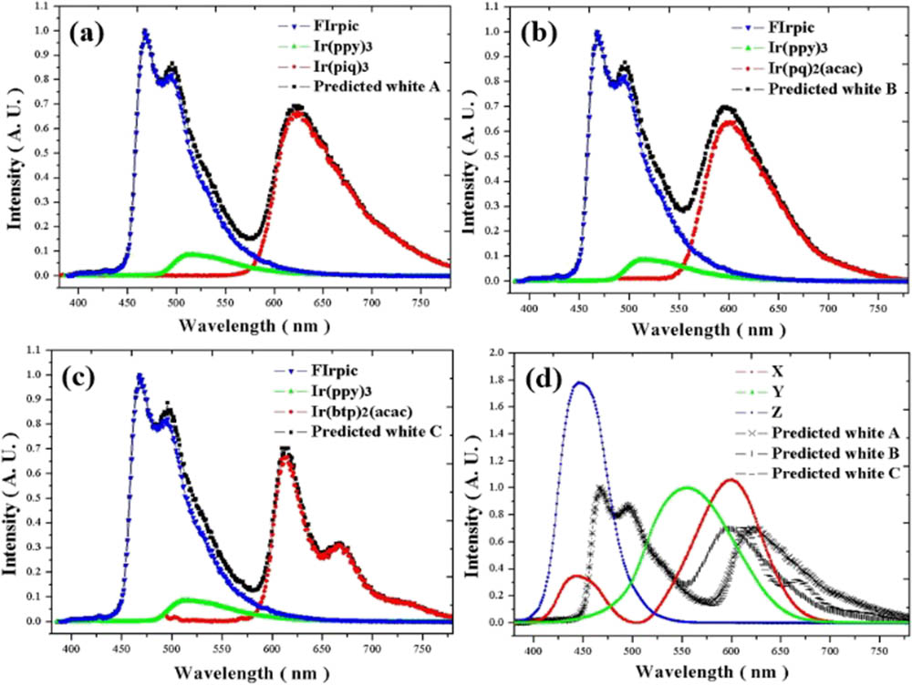
Fig. 2. (a–c) Predicted white OLED devices A, B, and C spectra (black line) combining the PL of the RGB of each dopant and the comparison based upon the CMF formula of X, Y, and Z.
Fig. 3. (a–c) Luminous efficiencies – luminance characteristics of white PHOLEDs with different red phosphorescent dopants and (d) a comparison between optimized white PHOLEDs with 0.6%, 0.4%, and 0.8% dopant concentration, respectively.
Fig. 4. CIE XY Ir ( piq ) 3 Ir ( pq ) 2 ( acac ) Ir ( btp ) 2 ( acac )
Fig. 5. PL spectrum of mCP, FIrpic, and Ir ( ppy ) 3 Ir ( piq ) 3 Ir ( pq ) 2 ( acac ) Ir ( btp ) 2 ( acac )
Fig. 6. J-V characteristics of white PHOLEDs with different red phosphorescent dopants: (a) Ir ( piq ) 3 Ir ( pq ) 2 ( acac ) Ir ( btp ) 2 ( acac )
|
Table 1. Schematic of the Different Red Phosphorescent Dopant Materials and Concentration Used in White PHOLEDs
|
Table 2. Summary of Electrical and Optical Properties of Optimized White PHOLEDs with Different Red Dopants A3, B2, and C4

Set citation alerts for the article
Please enter your email address
© Copyright 2018-2021 | Chinese Laser Press. All Rights Reserved 沪ICP备15018463号-20