Author Affiliations
1 National Engineering Research Center for Laser Processing, School of Optical and Electronic Information, Huazhong University of Science and Technology, Wuhan, Hubei 430074, China2 Research Institute of Huazhong University of Science and Technology in Shenzhen, Shenzhen, Guangdong 518057, Chinashow less
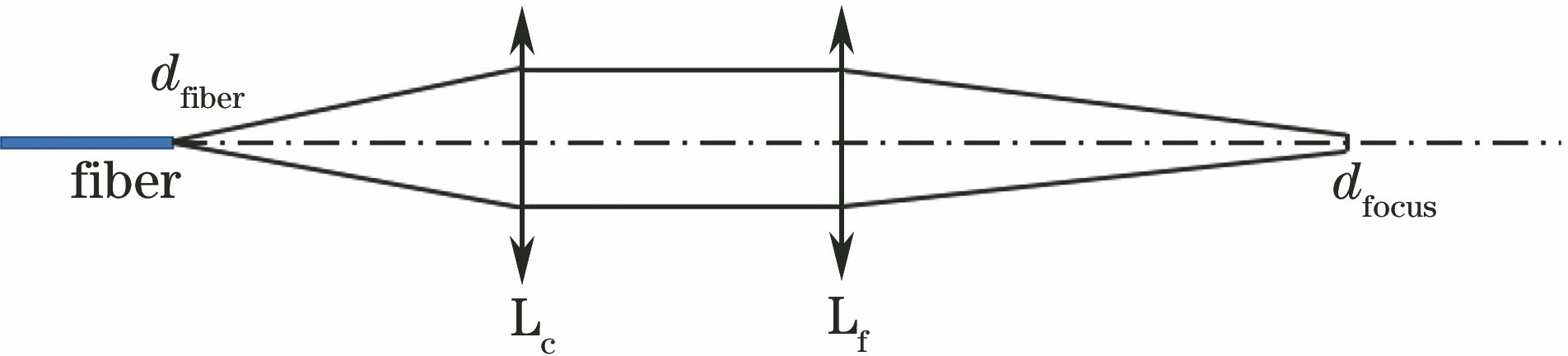
Fig. 1. Laser cutting system with two lens
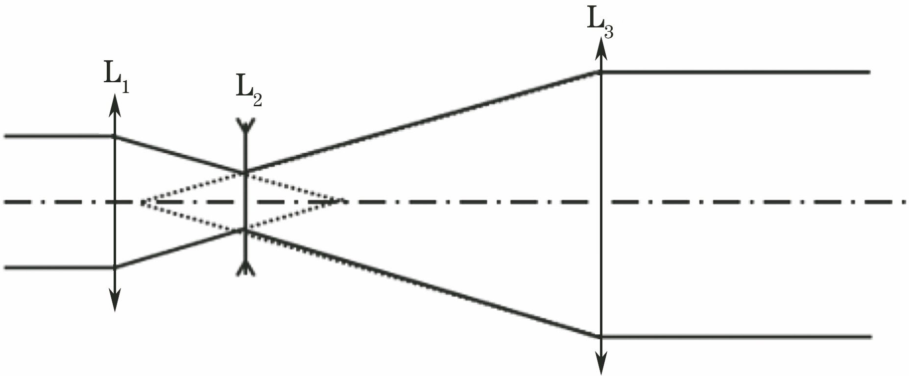
Fig. 2. Zoom beam expander system
Fig. 3. Variable spot and zoom laser system with five lens
Fig. 4. Variable spot and zoom laser system with four lens
Fig. 5. Principle of beam expander system
Fig. 6. Geometric locus of zoom group and compensated group
Fig. 7. Simulation results with MATLAB software
Fig. 8. Amplification diagram of focal spot
Fig. 9. Change of focal movement distance with the movement distance of compensated group
Fig. 10. Optical system, focusing surface spot, and wavefront aberration with different magnifications
| d1 | d2 | f'12 | M |
|---|
| 0<d1<f'1+f'2,d1↑ | d2<f'3,d2↓ | f'12<0, |f'12|↑ | ↓ | | f'1+<d1<f'1,d1↑ | d2>f'3,d2↓ | f'12>0,|f'12|↓ | ↑ | | d1=f'1 | d2=f'3 | f'12=f'1 | M=|f'3/f'1| | | f'1+f'2-d1<f'2 ,d1↑ | d2<f'3,d2↓ | f'12>0 ,|f'12|↓ | ↑ |
|
Table 1. Change of all items when zoom group is moved
| M | k | d1 /mm | d2 /mm |
|---|
| 0.4 | 3.750 | 64.53 | 17.00 | | 0.6 | 2.500 | 60.80 | 52.00 | | 0.8 | 1.875 | 57.07 | 69.00 | | 1.0 | 1.500 | 53.33 | 80.07 | | 1.2 | 1.250 | 49.60 | 87.00 | | 1.4 | 1.070 | 45.87 | 92.00 | | 1.5 | 1.000 | 44.00 | 94.00 |
|
Table 2. Values of d1 and d2 with different magnifications
| M | k | Coordinate position /mm |
|---|
| Zoom group | Compensated group |
|---|
| 0.4 | 3.750 | 164.53 | 181.53 | | 0.6 | 2.500 | 160.80 | 212.80 | | 0.8 | 1.875 | 157.07 | 226.07 | | 1.0 | 1.500 | 153.33 | 233.40 | | 1.2 | 1.250 | 149.60 | 236.60 | | 1.4 | 1.070 | 145.87 | 237.87 | | 1.5 | 1.000 | 144.00 | 238.00 |
|
Table 3. Coordinate positions of zoom group and compensated group with different magnifications
| Item | Surface type | Radius /mm | Thickness /mm | Glass material | Conic coefficient |
|---|
| OBJ | Standard | Infinity | Infinity | | 0 | | STO | Standard | 107.35 | 3.00 | Silica | 0 | | 2 | Standard | -85.81 | 1.00 | | 0 | | 3 | Standard | 39.17 | 3.00 | Silica | -0.94 | | 4 | Standard | 518.98 | 47.33 | | 0 | | IMA | Standard | Infinity | | | 0 |
|
Table 4. Parameters of fixed group calculated by Zemax software
| Item | Surface type | Radius /mm | Thickness /mm | Glass material | Conic coefficient |
|---|
| OBJ | Standard | Infinity | Infinity | | 0 | | STO | Standard | 2.94×10⁷ | 2.00 | Silica | 0 | | 2 | Standard | 13.04 | -29.00 | | -2.10 | | IMA | Standard | Infinity | | | 0 |
|
Table 5. Parameters of zoom group calculated by Zemax magnification
| Item | Surface type | Radius /mm | Thickness /mm | Glass material | Conic coefficient |
|---|
| OBJ | Standard | Infinity | Infinity | | 0 | | STO | Standard | 98.94 | 5 | Silica | 0 | | 2 | Standard | 58.34 | 2 | | 1.86 | | 3 | Standard | 38.68 | 5 | Silica | 0 | | 4 | Standard | 240.66 | 144 | | 0 | | IMA | Standard | Infinity | | | 0 |
|
Table 6. Parameters of compensated group and focusing lens calculated by Zemax magnification
| Item | Surface type | Radius /mm | Thickness /mm | Glass material | Conic coefficient |
|---|
| OBJ | Standard | Infinity | Infinity | | 0 | | STO | Standard | 107.35 | 3.00 | Silica | 0 | | 2 | Standard | -85.81 | 1.00 | | 0 | | 3 | Standard | 39.17 | 3.00 | Silica | -0.94 | | 4 | Standard | 518.98 | 39.38 | | 0 | | 5 | Standard | -45.68 | 2.00 | Silica | -22.44 | | 6 | Standard | 17.43 | 87.12 | | 0 | | 7 | Standard | 703.05 | 5.00 | Silica | 0 | | 8 | Standard | 95.62 | 2.00 | | 0 | | 9 | Standard | 76.59 | 5.00 | Silica | 0 | | 10 | Standard | -94.75 | 25.00 | | 0 | | 11 | Standard | 98.94 | 5.00 | Silica | 0 | | 12 | Standard | 58.39 | 2.00 | | 1.86 | | 13 | Standard | 38.68 | 5.00 | Silica | 0 | | 14 | Standard | 240.66 | 144.01 | | 0 | | IMA | Standard | Infinity | | | 0 |
|
Table 7. Parameters of system after optimization
| M | k | d1/mm | d2/mm |
|---|
| 0.4 | 3.750 | 60.27 | 11.17 | | 0.6 | 2.500 | 55.75 | 50.26 | | 0.8 | 1.875 | 50.28 | 70.42 | | 1.0 | 1.500 | 45.34 | 80.07 | | 1.2 | 1.250 | 42.10 | 84.33 | | 1.4 | 1.070 | 40.08 | 86.45 | | 1.5 | 1.000 | 39.38 | 87.12 |
|
Table 8. Values of d1 and d2 calculated at different magnification after optimization
| Front R /mm | Back R /mm | Thickness /mm | Decenter X /mm | Decenter Y /mm | Tilt X | Tilt Y |
|---|
| ±0.15 | ±0.15 | ±0.15 | ±0.15 | ±0.15 | ±0.1 | ±0.1 |
|
Table 9. Tolerance parameters of this system