Author Affiliations
1Beijing Institute of Space Mechanics and Electricity, Beijing 100094, China2Key Laboratory for Advanced Optical Remote Sensing Technology of Beijing, Beijing 100094, Chinashow less
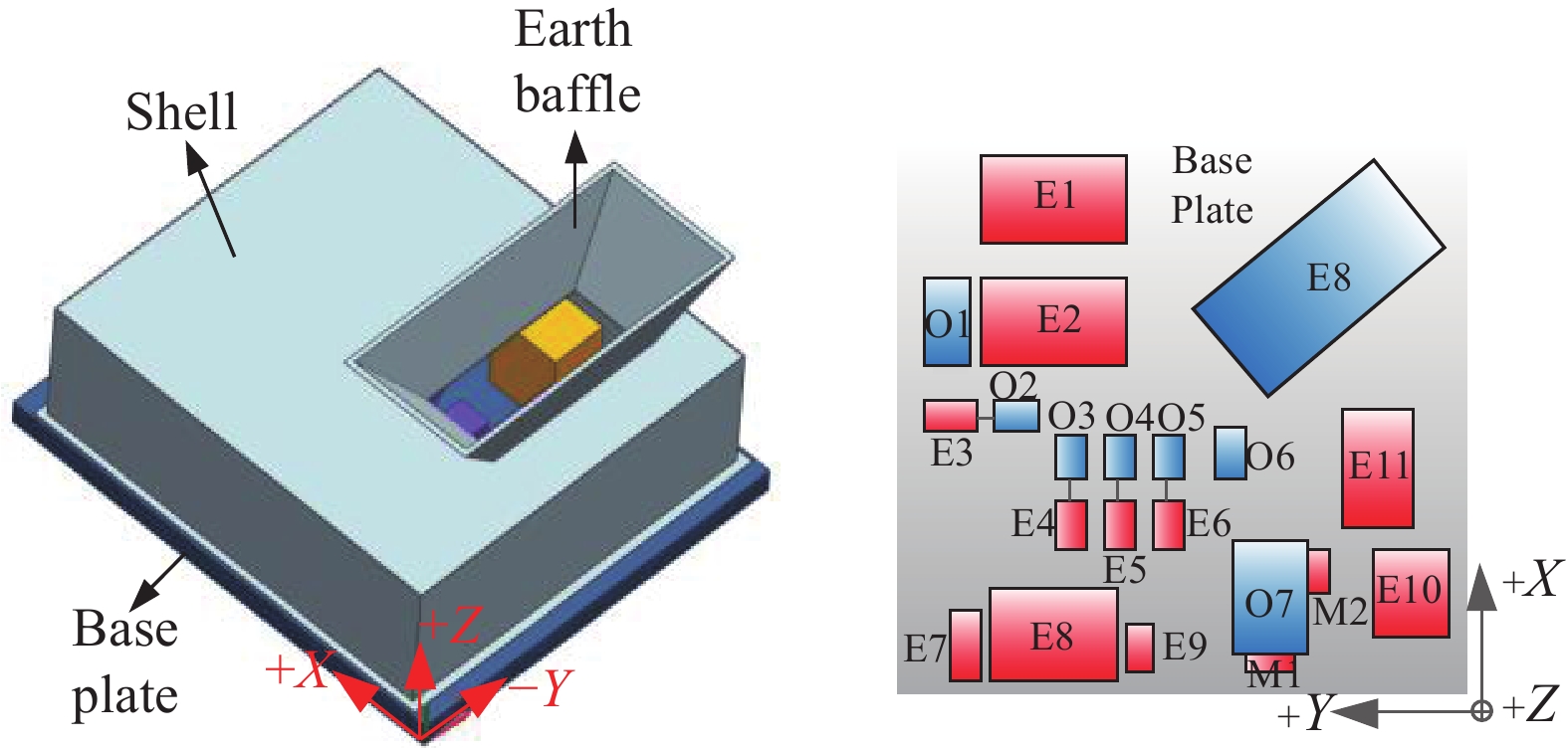
Fig. 1. Structure layout of gas monitoring sensor
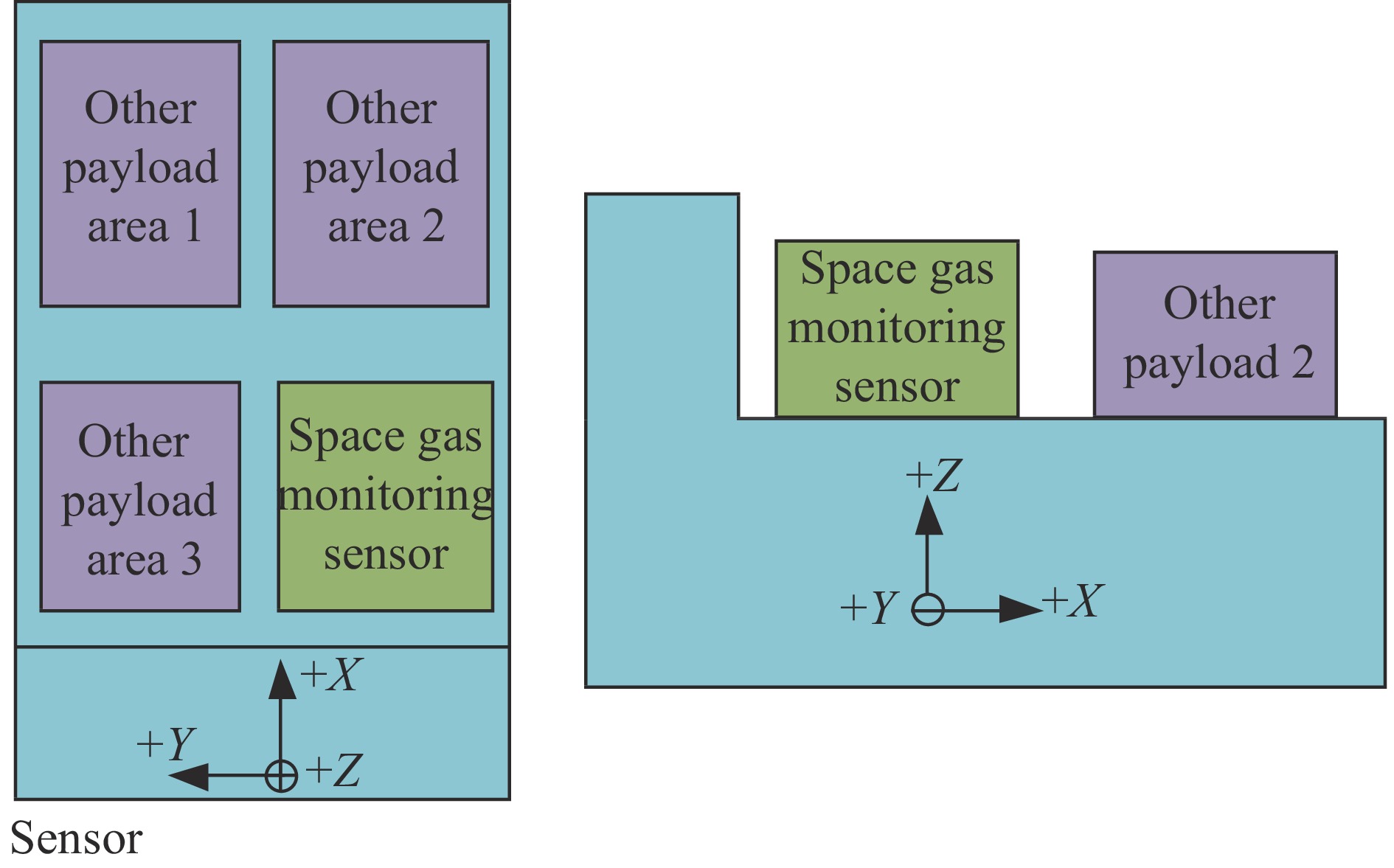
Fig. 2. Payloads' deployment on satellite
Fig. 3. Schematic diagram of lens 7 components and voice coil motor
Fig. 4. Thermal control scheme of gas monitoring sensor
Fig. 5. Heat dissipation schemes of electronic devices 1-2 and 7-11(E: electric device)
Fig. 6. Insulation installation method between electronic devices and base plate
Fig. 7. Heat dissipation schemes of electronic devices 3-6(E: electric device; O: optical lens)
Fig. 8. Heat dissipation schemes of voice coil motor
Fig. 9. Simulation tool of satellite platform
Fig. 10. Temperature curves of main components on gas monitoring sensor under hot and cold case condition
| Calorigenic
equipments
| Stand by
mode/W
| Observation
mode/W
| Calibration
mode/W
| Operating
time on
orbit/min
| | Electric device 1 | 11 | 11 | 11 | 102 | | Electric device 2 | 0 | 3 | 3 | 68 | | Electric device 3 | 0 | 0.3 | 0.3 | 63 | | Electric device 4 | 0.9 | 1.2 | 1.2 | 102 | | Electric device 5 | 0.9 | 1.2 | 1.2 | 102 | | Electric device 6 | 0.9 | 1.2 | 1.2 | 102 | | Electric device 7 | 0 | 0 | 4 | 3 | | Electric device 8 | 0 | 20 | 20 | 63 | | Electric device 9 | 0 | 0 | 21.1 | 3 | | Electric device 10 | 8 | 8 | 8 | 102 | | Electric device 11 | 0 | 4 | 4 | 52 | | Voice coil motor | 0 | 2 | 2 | 52 | | Stepper motor | 0 | 1.7 | 1.7 | 52 |
|
Table 1. Heat consumption and operating time of calorigenic equipments
| Components | Temperature requirement/℃ | | Operating time | Non-operating time | | Optical lens 7 | 19±3 | 19±7 | | Optical lens 1–6,8 | 20±2 | | Voice coil motor of optical lens 7 | 0–85 | | Stepper motor of optical lens 7 | –10–80 | | Electric device 1,2,7–11 | –10–45 | | Electric device 3–6 | 0–20 |
|
Table 2. Temperature control requirements of gas monitoring sensor components
| Thermal boundary conditions | Simulation methods during ground test | | Vacuum and space cold black background | Use space environment simulator | | Thermal environment on satellite platform | Design simulation tool of satellite platform,which is shown in Fig.9, Fig.5Control the temperature of simulation tool according to the given temperature boundary of satellite;
Cover simulation tool surfaces facing gas monitoring sensor with MLI and put heating circuit on surface of the MLI to obtain orbit heat flux absorbed by MLI
| | Orbit heat flux | Use infrared heating cage and flux sensor to abtain heat flux incidenting to the entrance of earth baffle;
Put heating circuit on MLI surfaces and radiator back surface to obtain orbit heat flux absorbed by them
| | Heat consumption of calorigenic equipments | Calorigenic equipments of gas monitoring sensor operate during test according to the normal working mode on orbit |
|
Table 3. Thermal boundary conditions of gas monitoring sensor on orbit and simulation methods of these conditions during ground test
| Case | Orbit heat flux | One orbit working mode | Temperature boundary
of satellite/℃
| | Cold case | Minimum heat flux throughout the life cycle | Standby mode | −5 | | Hot case | Maximum heat flux throughout the life cycle | Standby mode→calibration mode→
observation mode→standby mode
| 45 |
|
Table 4. Operating conditions of test
| Components | Cold
case
| Hot
case
| Temperature
requirement
| | Optical lens 1 | 18.8−19 | 20.4−20.9 | 20±2 | | Optical lens 2 | 20.8−21.0 | 20.8−21.0 | 20±2 | | Optical lens 3 | 19.6−19.8 | 19.8−20.0 | 20±2 | | Optical lens 4 | 21.3−21.5 | 21.0−21.3 | 20±2 | | Optical lens 5 | 19.9−20.0 | 19.9−20.1 | 20±2 | | Optical lens 6 | 20.2−20.5 | 20.5−21.1 | 20±2 | | Optical lens 8 | 19.1−20.0 | 20.4−21.2 | 20±2 | | Optical lens 7 | 16−16.6 | 19.1−20.3 | Operating time19±3
Non-operating time19±7
| | Electric device 1 | 9.2−12 | 14.2−19.1 | −10−45 | | Electric device 2 | 19.8−20.4 | 26.7−27.3 | −10−45 | | Electric device 3 | 8.4−9.7 | 9.5−12.4 | 0−20 | | Electric device 4 | 8.8−10.0 | 9.9−12.8 | 0−20 | | Electric device 5 | 8.7−9.9 | 9.9−12.7 | 0−20 | | Electric device 6 | 8.4−10.0 | 9.5−12.8 | 0−20 | | Electric device 7 | 2.6−4.5 | 17.1−21.7 | −10−45 | | Electric device 8 | 4.8−6.5 | 20.1−24.2 | −10−45 | | Electric device 9 | 4.5−6.6 | 20.0−24.1 | −10−45 | | Electric device 10 | 11.1−12.5 | 22.3−26.0 | −10−45 | | Electric device 11 | 9.1−10.8 | 19.0−24.8 | −10−45 | | Voice coil motor | 14.4−16.3 | 17.9−35.6 | 0−85 | | Stepper motor | 18.5−18.6 | 28.7−35.9 | −10−80 |
|
Table 5. Summary of test results(Unit: ℃)